


 Loading...
HP B-series 16Gb FC Switches
Quick Start Instructions
Overview
Read these instructions to set up and configure the HP SN6000B 16Gb 48-port Fibre Channel Switch and HP SN3000B 16Gb 24-port Fibre Channel Switch.
These instructions provide basic configuration steps. For detailed rack mount and configuration instructions, download the HP B-series 16Gb Switches Hardware Reference Guide from the storage section of the HP website: http://www.hp.com/support/manuals.
Figure 1 (page 1) shows the port side of the 48-port switch.
SN6000B 16Gb 48-port FC switch
Figure 1 Port side of the 48-port FC Switch
1. System status LED |
6. FC ports (44-47) |
2. Management Ethernet port |
7. FC ports (4-7) |
with LEDs |
|
3. USB port |
8. Switch ID pull-out tab |
4. FC ports (0-3) |
9. Serial console port |
5. FC ports (40-43) |
10. System power LED |
© Copyright 2012 Hewlett-Packard Development Company, L.P. Printed in the U.S.
HP Part Number: 5697-1520
Published: March 2012 *5697-1520*
Edition: 1
Verify the SN6000B 16Gb 48-port FC switch carton contents
Verify that the carton contains the following (any SFPs ordered will not be in this carton; they will be packaged separately):
•One HP SN6000B 16Gb 48-port FC Switch with two integrated power supply/fan assemblies
•Rubber feet, required to set up the switch as a standalone unit
•Serial cable with an RJ-45 connector plus an adaptor for RJ-45 to DB9
•HP SAN Network Advisor DVD
•Brocade EZ Switch and China ROHS documentation
Page 1

•One accessory kit with the following items:
◦Rack Mount Kit, including rails, rail mounting hardware, and plenum
◦HP product documentation, including Read Me First, Safety Guides, End User License Agreement and Warranty
•Two power cords
SN3000B 16Gb 24-port FC switch
Figure 2 (page 2) shows the port side of the 24-port switch.
Figure 2 Port side of the 24-port switch
1. System status LED |
5. System power LED |
2. Management Ethernet port |
6. Serial console port |
with LEDs |
|
3. USB port |
7. Switch ID pull-out tab |
4. FC ports (0-3) |
8. FC ports (4–7) |
Verify the SN3000B 16Gb 24-port FC switch carton contents
Verify that the carton contains the following (any SFPs ordered will not be in this carton; they will be packaged separately):
•One HP SN3000B 16Gb 24-port FC Switch with one integrated power supply/fan assembly
•Rubber feet, required to set up the switch as a standalone unit
•Serial cable with an RJ-45 connector plus an adaptor for RJ-45 to DB9
•HP SAN Network Advisor DVD
•Brocade EZ Switch and China ROHS documentation
•One accessory kit with the following items:
◦Rack Mount Kit, including rails, rail mounting hardware, and plenum
◦HP product documentation, including Read Me First, Safety Guides, End User License Agreement and Warranty
•One power cord
NOTE: The HP SN3000B 16Gb Fibre Channel Switch can, as an option, be configured with a second power supply/fan assembly, which must be ordered separately.
Verify the SN6000B and SN3000B 16Gb FC Switches installation requirements
To set up the switch for the first time, you will need the following:
•Workstation with an installed terminal emulator (such as HyperTerminal)
•Unused IP address and corresponding subnet mask and gateway address
•Serial cable (supplied with the switch)
•Ethernet cable
•Access to an FTP server, SCP server, or USB device for backing up the switch configuration (optional)
•HP B-series SFP+ transceivers and compatible cables (HP B-series 16 Gb/s SFP+ transceivers required for 16 Gb/s performance), as required
IMPORTANT: Order transceivers or cables separately. The HP SN6000B and SN3000B 16Gb FC Switches support only transceivers and cables labeled B-series SFP+, or B-series cable. See the compatibility matrix at http:// hpsancompat.com/ for more information on supported transceivers.
Plan the SN6000B and SN3000B 16Gb FC Switches site environment
To ensure adequate cooling, install the switch with the nonport side (which contains the air intake vents) facing the cool-air aisle. Verify that the ambient air temperature does not exceed 40°C (104°F) and that the ambient humidity remains between 10% and 85% while the switch is operating.
NOTE: You must install the plenum if the switch is to be installed in a rack.
Page 2
To install and operate the switch successfully, ensure that:
•The primary AC input is 85–264 VAC Nominal: 100–40 VAC, 2.0 A; 47–63 Hz. The switch autosenses input voltage.
•The primary outlet is wired correctly, protected by a circuit breaker, and grounded in accordance with local electrical codes.
•The supply circuit, line fusing, and wire size are adequate, as specified by the electrical rating on the switch nameplate.
For additional power supply information, see the HP B-series 16Gb Switches Hardware Reference Guide.
Installing the SN6000B and SN3000B 16Gb FC Switches in a rack using the Rack Mount Kit
You can use the SN6000B and SN3000B Switch Rack Mount Kits to install your HP SN6000B and SN3000B 16Gb FC Switches in HP 10000 Series Racks.
CAUTION: Install the Rack Mount Kit as described in this section so that when the switch is installed, the port side faces the rear of the rack. This configuration optimizes performance by:
•Providing better airflow by using a plenum to force cool air to enter the switch from the front of the rack
•Providing room for a gradual bend in the fiber optic cables because the port side of the switch is set back from the edge of the rack
Use only the screws provided in the Rack Mount Kit. Using other screws can cause damage to internal components.
To install the switch in a rack using the Rack Mount Kit:
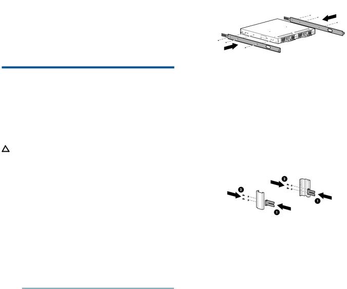
1.Place the switch on a flat surface and attach each inner rail to the switch using three flat-head screws as shown in Figure 3 (page 3).
The rails are labeled Left and Right to designate the left side and right side of the switch as viewed from its nonport side.
Figure 3 Attaching the inner rails to the switch
2.Choose a rack mounting location that provides clearance for the switch power cords to run between the rack sides and the rails at the front of the rack.
3.Attach each rear mounting bracket to a rear rack upright column using two Phillips screws and adapter washers. See Figure 4 (page 3).
Figure 4 Installing the rear mounting brackets
Page 3
Loading...