


Compaq StorageWorks™
RAID Array 3000 Controller Shelf
Hardware
User’s Guide
Fourth Edition (January 2001)
Part Number EK-SMCPQ-UG. D01
Compaq Computer Corporation
© 2001 Compaq Computer Corporation.
COMPAQ, the Compaq logo and StorageWorks Registered with the U.S. Patent and Trademark Office.
Microsoft, MS-DOS, Windows, and Windows NT are trademarks of Microsoft Corporation.
All other product names mentioned herein may be trademarks of their respective companies.
Confidential computer software. Valid license from Compaq required for possession, use or copying. Consistent with FAR 12.211 and 12.212, Commercial Computer Software, Computer Software Documentation, and Technical Data for Commercial Items are licensed to the U.S. Government under vendor's standard commercial license.
Compaq shall not be liable for technical or editorial errors or omissions contained herein. The information in this document is subject to change without notice.
THE INFORMATION IN THIS PUBLICATION IS PROVIDED “AS IS” WITHOUT WARRANTY OF ANY KIND. THE ENTIRE RISK ARISING OUT OF THE USE OF THIS INFORMATION REMAINS WITH RECIPIENT. IN NO EVENT SHALL COMPAQ BE LIABLE FOR ANY DIRECT, CONSEQUENTIAL, INCIDENTAL, SPECIAL, PUNITIVE OR OTHER DAMAGES WHATSOEVER (INCLUDING WITHOUT LIMITATION, DAMAGES FOR LOSS OF BUSINESS PROFITS, BUSINESS INTERRUPTION OR LOSS OF BUSINESS INFORMATION), EVEN IF COMPAQ HAS BEEN ADVISED OF THE POSSIBILITY OF SUCH DAMAGES AND WHETHER IN AN ACTION OF CONTRACT OR TORT, INCLUDING NEGLIGENCE.
The limited warranties for Compaq products are exclusively set forth in the documentation accompanying such products. Nothing herein should be construed as constituting a further or additional warranty.
RAID Array 3000 Controller Shelf Hardware User's Guide
Fourth Edition (January 2001)
Part Number EK-SMCPQ-UG. D01
Contents
About This Guide
Purpose and Scope................................................................................................. |
ix |
Intended Audience ................................................................................................. |
ix |
Document Structure ............................................................................................... |
ix |
Related Documents ................................................................................................ |
xi |
Text Conventions.................................................................................................. |
xii |
Symbols in Text.................................................................................................... |
xii |
Symbols on Equipment ........................................................................................ |
xiii |
Rack Stability ...................................................................................................... |
xiv |
Getting Help ........................................................................................................ |
xiv |
Compaq Technical Support ........................................................................... |
xiv |
Compaq Website............................................................................................ |
xv |
Compaq Authorized Reseller.......................................................................... |
xv |
Chapter 1
Product Overview
Product Description ............................................................................................. |
1-1 |
Controller Shelf Features ..................................................................................... |
1-6 |
Controller Shelf Enclosure ................................................................................... |
1-6 |
Shelf Cabinet ....................................................................................................... |
1-8 |
RAID Array 3000 Controller......................................................................... |
1-8 |
Device I/O Module ....................................................................................... |
1-9 |
Host I/O Module ......................................................................................... |
1-12 |
Shelf Cooling.............................................................................................. |
1-13 |
Controller Shelf Power Supplies.................................................................. |
1-14 |
UPS ............................................................................................................ |
1-14 |
6-Slot Device Expansion Shelf (Optional) .......................................................... |
1-15 |
Connecting the Controller Shelf to a Host System............................................... |
1-16 |
Specifications .................................................................................................... |
1-21 |
iv RAID Array 3000 Controller Shelf Hardware User's Guide
Chapter 2
RAID Array 3000 Controller
Controller Overview ............................................................................................ |
2-1 |
Controller Features .............................................................................................. |
2-3 |
Controller Reset and LED Indicators.................................................................... |
2-5 |
Flexible RAID Set Configuration ......................................................................... |
2-6 |
Custom Components ..................................................................................... |
2-7 |
Efficient Write and Read Algorithms............................................................. |
2-7 |
RAID Levels Supported ....................................................................................... |
2-9 |
RAID 0....................................................................................................... |
2-10 |
RAID 1....................................................................................................... |
2-11 |
RAID 0+1................................................................................................... |
2-12 |
RAID 4....................................................................................................... |
2-14 |
RAID 5....................................................................................................... |
2-16 |
JBOD ......................................................................................................... |
2-17 |
Redundant Operation ......................................................................................... |
2-17 |
Initialization ............................................................................................... |
2-18 |
Message Passing ......................................................................................... |
2-18 |
Failover ...................................................................................................... |
2-18 |
Environmental ................................................................................................... |
2-19 |
Backup Power Management ........................................................................ |
2-19 |
Chapter 3
Installation and Maintenance
Installation Guidelines ......................................................................................... |
3-1 |
Installing Shelves in the Cabinet .......................................................................... |
3-2 |
Installing Shelf Supports ............................................................................... |
3-7 |
Installing UPS Brackets .............................................................................. |
3-10 |
Power and SCSI Cable Connection Procedures................................................... |
3-14 |
SCSI Bus Target Addresses and Termination............................................... |
3-15 |
Cabling a Single Device Expansion Shelf Subsystem................................... |
3-16 |
Cabling a Two Device Expansion Shelf Subsystem ..................................... |
3-19 |
Cabling a Three Device Expansion Shelf Subsystem.................................... |
3-21 |
Cabling a Four Device Expansion Shelf Subsystem ..................................... |
3-23 |
Controller Shelf Status LED’s ............................................................................ |
3-27 |
Controller Status LEDs ...................................................................................... |
3-28 |
Replacing Field Replaceable Units (FRUs)......................................................... |
3-28 |
Replacing a Host or Device I/O SBB........................................................... |
3-30 |
Replacing a Power Supply SBB .................................................................. |
3-31 |
Replacing the RAID Controller ................................................................... |
3-32 |
Replacing the UPS ...................................................................................... |
3-33 |
Replacing a Blower..................................................................................... |
3-33 |
Replacing the Controller Memory Cache Modules....................................... |
3-35 |
|
Contents v |
Chapter 4 |
|
Second Controller Option |
|
Installing the Upgrade.......................................................................................... |
4-2 |
Saving the Existing Configuration ................................................................. |
4-3 |
Updating Firmware ....................................................................................... |
4-5 |
Shutting down the RA3000 ........................................................................... |
4-7 |
Installing Two SIMMs into Second Controller............................................... |
4-8 |
Replace Existing Controller........................................................................... |
4-9 |
Restoring the Configuration ........................................................................ |
4-10 |
Updating the Firmware on a Second Controller............................................ |
4-11 |
Installing theOriginal Controller.................................................................. |
4-11 |
Configuring a Dual-Controller Installation for a Single Serial Port...................... |
4-12 |
Configuring the RA3000 for the Active Mode of Operation ......................... |
4-12 |
Configuring the Dual Controllers................................................................. |
4-13 |
Connecting to Your Dual-Controller Storage System ................................... |
4-15 |
Verifying the Controller Operating Parameters ............................................ |
4-15 |
List of Figures
Figure 1-1. |
RAID Array 3000 Controller Shelf .................................................... |
1-2 |
Figure 1-2. |
RAID Array 3000 6-slot Device Expansion Shelf (optional) .............. |
1-3 |
Figure 1-3. |
Controller shelf major components .................................................... |
1-7 |
Figure 1-4. |
RAID Array 3000 controller.............................................................. |
1-8 |
Figure 1-5. |
Device I/O module .......................................................................... |
1-10 |
Figure 1-6. |
Device I/O module blower-status LEDs........................................... |
1-11 |
Figure 1-7. |
Host I/O module ............................................................................. |
1-12 |
Figure 1-8. |
Power supply .................................................................................. |
1-14 |
Figure 1-9. |
Single host, single adapter, with one active controller ...................... |
1-17 |
Figure 1-10. |
Single host, single adapter, with two active controllers................... |
1-18 |
Figure 1-11. |
Single host, dual adapter, two ports with two active controllers...... |
1-19 |
Figure 1-12. |
Dual host, single adapter, with one active controller per host.......... |
1-20 |
Figure 2-1. |
RAID Array 3000 single controller block diagram............................. |
2-2 |
Figure 2-2. |
Bridging the gap between the host and device expansion shelf ........... |
2-3 |
Figure 2-3. |
Storagesets, partitions, and disk drives............................................... |
2-4 |
Figure 2-4. |
Controller front panel ........................................................................ |
2-6 |
Figure 2-5. |
RAID 0 write .................................................................................. |
2-10 |
Figure 2-6. |
Diagram of a RAID 1 write ............................................................. |
2-11 |
Figure 2-7. |
Diagram of RAID 0+1 write............................................................ |
2-12 |
Figure 2-8. |
Diagram of a RAID 4 write ............................................................. |
2-14 |
Figure 2-9. |
Diagram of a RAID 5 write ............................................................. |
2-16 |
Figure 3-1. |
Recommended single expansion shelf installation .............................. |
3-3 |
Figure 3-2. Recommended controller shelf installation (two expansion |
|
|
|
shelves) ........................................................................................... |
3-4 |
Figure 3-3. Recommended controller shelf installation (three expansion |
|
|
|
shelves) ........................................................................................... |
3-5 |
vi RAID Array 3000 Controller Shelf Hardware User's Guide |
|
|
Figure 3-4. Recommended controller shelf installation (four expansion |
|
|
|
shelves)........................................................................................... |
3-6 |
Figure 3-5. |
RETMA cabinet shelf supports........................................................ |
3-10 |
Figure 3-6. |
UPS rack-mount bracket assemblies ................................................ |
3-12 |
Figure 3-7. |
UPS bracket RETMA and metric hole locations (front).................... |
3-12 |
Figure 3-8. |
UPS bracket RETMA and metric hole locations (rear) ..................... |
3-13 |
Figure 3-9. |
Controller/ single device expansion shelf cabling diagram ............... |
3-17 |
Figure 3-10. |
AC power wiring diagram ............................................................. |
3-18 |
Figure 3-11. Controller/ two device expansion shelf cabling diagram................. |
3-20 |
|
Figure 3-12. |
Controller/ three device expansion shelf cabling diagram ............... |
3-22 |
Figure 3-13. Controller/ four device expansion shelf cabling diagram ................ |
3-25 |
|
Figure 3-14. Shelf status LEDs.......................................................................... |
3-27 |
|
Figure 3-15. |
Controller shelf FRUs ................................................................... |
3-29 |
Figure 3-16. |
Replacing the host I/O SBB........................................................... |
3-30 |
Figure 3-17. |
Removing the controller from the shelf.......................................... |
3-32 |
Figure 3-18. |
Replacing a blower assembly ........................................................ |
3-34 |
Figure 3-19. |
Controller cache modules.............................................................. |
3-36 |
Figure 3-20. Release locking clips..................................................................... |
3-36 |
|
Figure 3-21. |
Remove installed SIMM modules.................................................. |
3-37 |
Figure 3-22. |
Install replacement SIMM............................................................. |
3-38 |
Figure 3-23. |
Pivot SIMM down to secure .......................................................... |
3-38 |
Figure 4-1. |
Saving the existing configuration ...................................................... |
4-3 |
Figure 4-2. |
Save Configuration dialog box .......................................................... |
4-4 |
Figure 4-3. |
Update firmware command ............................................................... |
4-5 |
Figure 4-4. |
Firmware Update dialog box ............................................................. |
4-6 |
Figure 4-5. Insert SIMM into connector .............................................................. |
4-8 |
|
Figure 4-6. |
Pivot SIMM down to seat.................................................................. |
4-8 |
Figure 4-7. |
Remove controller from top slot ........................................................ |
4-9 |
Figure 4-8. |
Restoring configuration to new controller ........................................ |
4-10 |
Figure 4-9. |
Restore Configuration dialog box .................................................... |
4-11 |
|
Contents vii |
List of Tables |
|
Table 1 Related Documents.................................................................................... |
xi |
Table 1-1 Controller Shelf Part Numbers and Model Descriptions ........................ |
1-4 |
Table 1-2 Single Host, Single Adapter, with One Active Controller .................... |
1-17 |
Table 1-3 Single Host, Single Adapter, with Two Active Controllers .................. |
1-18 |
Table 1-4 Single Host, Dual Adapter, Two Port with Two Active |
|
Controllers.......................................................................................... |
1-19 |
Table 1-5 Dual Host, Single Adapter, with One Active Controller per Host......... |
1-20 |
Table 1-6 Controller Shelf Technical Specifications ........................................... |
1-21 |
Table 1-7 Controller Shelf Power and Physical Specifications ............................ |
1-24 |
Table 2-1 LED/Reset Switch Interface ................................................................. |
2-5 |
Table 2-2 Raid Levels Supported ......................................................................... |
2-9 |
Table 2-3 Shelf RAID Set Restrictions ................................................................. |
2-9 |
Table 2-4 RAID 0+1 Example............................................................................ |
2-13 |
Table 2-5 Response to Various AC Power Conditions ........................................ |
2-19 |
Table 3-1 Shelf Support Mounting Kits and Installation Guides ............................ |
3-7 |
Table 3-2 RETMA Cabinet Shelf Support Parts List ............................................. |
3-8 |
Table 3-3 UPS Rack-mount Bracket Mounting Hardware List ............................ |
3-11 |
Table 3-4 Controller Shelf Field Replaceable Units ............................................ |
3-29 |
About This Guide
Purpose and Scope
This guide is designed to provide an overview for installers and operators of the Compaq StorageWorksTM RAID Array 3000 Controller Shelf User’s Guide.
Intended Audience
This document is written for installers and operators.
Document Structure
This guide contains the following information:
Chapter 1: Product Overview
■Product description
■Controller Shelf Features
■Controller Shelf Enclosure
■Shelf Cabinet
■6-Slot Device Expansion Shelf (Optional)
■Connecting the Controller Shelf to a Host System
■Specifications
x RAID Array 3000 Controller Shelf Hardware User's Guide
Chapter 2: RAID Array 3000 Controller
■Controller Overview
■Controller Features
■Controller Reset and LED Indicators
■Flexible Raid Set Configuration
■RAID Levels Supported
■Redundant Operation
■Environmental
Chapter 3: Installation and Maintenance
■Installation Guidelines
■Installing Shelves in the Cabinet
■Power and SCSI Cable Connection Procedures
■Controller Shelf Status LEDs
■Controller Status LEDs
■Replacing Field Replaceable Units (FRUs)
Chapter 4: Second Controller Option
■Installing the Upgrade
■Configuring a Dual-Controller Installation for a Single Serial Port
About This Guide xi
Related Documents
In addition to this guide, the following documentation is useful to the reader:
Table 1
Related Documents
Document Title |
Part Number |
|
|
RAID Array 3000 Subsystem Second |
EK-SM3KC-IG.E01 |
Controller Option Installation Guide |
|
|
|
Command Console V2.2 for the RAID Array |
AA-RBF2C-TE |
3000 (Pedestal and Rack Mount Models) |
|
User’s Guide |
|
|
|
RAID Array 3000 Pedestal Storage Subsystem |
EK-SMCPO-UG.C01 |
Hardware User’s Guide |
|
|
|

xii RAID Array 3000 Controller Shelf Hardware User's Guide
Text Conventions
This document uses the following conventions to distinguish elements of text:
Keys |
Keys appear in boldface. A plus sign (+) between |
|
two keys indicates that they should be pressed |
|
simultaneously. |
USER INPUT |
User input appears in a different typeface and in |
|
uppercase. |
FILENAMES |
File names appear in uppercase italics. |
Menu Options, |
These elements appear in initial capital letters. |
Command Names, |
|
Dialog Box Names |
|
COMMANDS, |
These elements appear in uppercase unless case |
DIRECTORY NAMES, |
sensitive. |
and DRIVE NAMES |
|
Type |
When you are instructed to type information, type |
|
the information without pressing the Enter key. |
Enter |
When you are instructed to enter information, type |
|
the information and then press the Enter key. |
Symbols in Text
The following symbols are found in the text of this guide to indicate different types of information.
WARNING: Text set off in this manner indicates that failure to follow directions in the warning could result in bodily harm or loss of life.
CAUTION: Text set off in this manner indicates that failure to follow directions could result in damage to equipment or loss of information.
IMPORTANT: Text set off in this manner presents clarifying information or specific instructions.

About This Guide xiii
NOTE: Text set off in this manner presents commentary, sidelights, or interesting points of information.
Symbols on Equipment
The following symbols are placed on equipment to indicate the presence of potentially hazardous conditions:
This symbol in conjunction with any of the following symbols indicates the presence of a potential hazard. The potential for injury exists if warnings are not observed. Consult your documentation for specific details.
This symbol indicates the presence of hazardous energy circuits or electric shock hazards. Refer all servicing to qualified personnel.
WARNING: To reduce the risk of injury from electric shock hazards, do not open this enclosure. Refer all maintenance, upgrades, and servicing to qualified personnel.
This symbol indicates the presence of electric shock hazards. The area contains no user or field serviceable parts. Do not open for any reason.
WARNING: To reduce the risk of injury from electric shock hazards, do not open this enclosure.
This symbol on an RJ-45 receptacle indicates a Network Interface
Connection.
WARNING: To reduce the risk of electric shock, fire, or damage to the equipment, do not plug telephone or telecommunications connectors into this receptacle.
This symbol indicates the presence of a hot surface or hot component. If this surface is contacted, the potential for injury exists.
WARNING: To reduce the risk of injury from a hot component, allow the surface to cool before touching.
xiv RAID Array 3000 Controller Shelf Hardware User's Guide
These symbols on power supplies or systems indicate the equipment is supplied by multiple sources of power.
WARNING: To reduce the risk of injury from electric shock, remove all power cords to completely disconnect power from the system.
Weight in kg Weight in lb
This symbol indicates that the component exceeds the recommended weight for one individual to handle safely.
WARNING: To reduce the risk of personal injury or damage to the equipment, observe local occupational health and safety requirements and guidelines for manual material handling.
Rack Stability
WARNING: To reduce the risk of personal injury or damage to the equipment, be sure that:
■The leveling jacks are extended to the floor.
■The full weight of the rack rests on the leveling jacks.
■The stabilizing feet are attached to the rack if it is a single rack installation.
■The racks are coupled together in multiple rack installations.
■Only one component is extended at a time. A rack may become unstable if more than one component is extended for any reason.
Getting Help
If you have a problem and have exhausted the information in this guide, you can get further information and other help in the following locations.
Compaq Technical Support
In North America, call the Compaq Technical Phone Support Center at 1-800-OK-COMPAQ. This service is available 24 hours a day, 7 days a week. For continuous quality improvement, calls may be recorded or monitored.
About This Guide xv
Outside North America, call the nearest Compaq Technical Support Phone Center. Telephone numbers for worldwide Technical Support Centers are listed on the Compaq website. Access the Compaq website:
http://www.compaq.com
Be sure to have the following information available before you call Compaq:
■Technical support registration number (if applicable)
■Product serial number
■Product model name and number
■Applicable error messages
■Add-on boards or hardware
■Third-party hardware or software
■Operating system type and revision level
Compaq Website
The Compaq website has information on this product. Access the Compaq website:
http://www.compaq.com/storage
Compaq Authorized Reseller
For the name of your nearest Compaq authorized reseller:
■In the United States, call 1-800-345-1518.
■In Canada, call 1-800-263-5868.
■Elsewhere, see the Compaq website for locations and telephone numbers
Chapter 1
Product Overview
This chapter provides an overall description of the Compaq StorageWorksTM RAID Array 3000 Controller Shelf (controller shelf) and its components. A series of cabling diagrams showing how to connect the controller shelf to a host system and a list of technical and environmental specifications is also included at the end of the chapter.
NOTE: This guide is the Hardware User’s Guide. For configuration information, refer to the Getting Started RAID Array 3000 Installation Guide and the Command Console V2.2 for the RAID Array 3000 (Pedestal and Rack Mount Models) User’s Guide.
Product Description
The controller shelf (Figure 1–1) is a rackmount storage system containing the basic components required to manage a storage array with two 16-bit, differential, UltraSCSI bus host interfaces. The devices, referred to as StorageWorks Building Blocks (SBBs), are disk drives from the StorageWorks family of storage devices. The release notes that accompanies the storage system lists the software solutions and disk drives that are supported.

1-2 RAID Array 3000 Controller Shelf Hardware User’s Guide
The controller shelf can be connected to one or up to four 6-slot device expansion shelves to form the complete RAID Array 3000 storage system (see Figure 1– 2). The Compaq StorageWorks BA356 Series Device Expansion Shelf (device expansion shelf) is offered as an option with a minimum of one shelf required. It contains six SBB slots for the disk drives, two power supplies, and a personality I/O module that connects the SCSI interface with the controller shelf. The device expansion shelf is supported by its own user’s guide (P/N EK–BA356–UG ) which must be used in conjunction with this document too properly install and configure your storage system.
NOTE: The device expansion shelf (DS-SWXRA-GN) must have a revision level of B01 (or higher) to operate with the controller shelf. Also, the Personality I/O module supplied with the shelf (P/N. 70-33067-02) must have a minimum revision level of H01 or higher.
The controller shelf and the accompanying device expansion shelves are installed in a standard RETMA or metric rackmount cabinet design. The device expansion shelves are typically mounted directly above the controller shelf in the cabinet. Each shelf is supplied with a bracket mounting kit to secure the unit into the desired cabinet design. The bracket kit for a metric cabinet is optional and must be ordered separately.
SHR-1034
Figure 1-1. RAID Array 3000 Controller Shelf

Product Overview 1-3
Figure 1-2 shows the RAID Array 3000 6-slot Device Expansion Shelf (optional).
SHR-1091
Figure 1-2. RAID Array 3000 6-slot Device Expansion Shelf (optional)
A battery-backup subsystem is included with the controller shelf in the form of a rackmount Uninterruptable Power Supply (UPS). In case of a power failure, the UPS provides temporary power to the storage system while it flushes its cache contents to disks. The UPS is normally installed in the lowest available slot in the cabinet.
CAUTION: The UPS is sized to perform this function for the controller and device expansion shelves only. No other electrical devices should be plugged into the UPS.
As an option, a second RAID controller module can be added for redundancy. The second controller operates in conjunction with the installed controller to protect data in case of a malfunction in the primary unit. The optional controller is installed directly below the primary controller in the center of the shelf (see Figure 1-3).
The controller shelf and its associated options are listed in Table 1– 1.

1-4 RAID Array 3000 Controller Shelf Hardware User’s Guide
Table 1-1
Controller Shelf Part Numbers and Model Descriptions
COMPAQ Part No.
DS-SWXRA-GH
DS-SWXRA-GK
Item Description
RA3000 UltraSCSI rackmount controller shelf with one controller, 120 V, which Includes:
One BA356 type shelf
One HSZ22 RAID controller with 16 MB of cache
Two 180 watt power supply SBBs, two dual-port, differential, ultra wide, host I/O modules
One dual-channel, wide, single-ended device I/O module
One 1000 watt UPS with rackmount bracket
One five meter host SCSI cable
Two 9-pin serial controller cables
Two Trilink SCSI cable adapters
One gray C13-to-125 V power cord
One black C13-to-125 V power cord
One controller shelf rackmount kit
User documentation.
Requires: Solutions Software kit for platform, host adapter, and disks.
Options: second HSZ22-AA controller and cache memory upgrade.
RA3000 UltraSCSI rackmount controller shelf with one controller, 230 V, which includes:
Except for power cord (DS-SWXRA-GK includes one black and one gray C13-to-230 V), same as DS-SWXRA-GH above.
continued
Product Overview 1-5
Table 1-1
Controller Shelf Part Numbers and Model Descriptions continued
COMPAQ Part No.
DS-SWXRA-GN
DS-HSZ22-AA
Item Description
RA3000 UltraSCSI rackmount 6-Slot storage expansion shelf which includes:
16-bit shelf assembly, two 180 watt power supply SBBs, 16-bit personality I/O assembly, shelf rack mounting kit, power cords, user documentation.
RA3000 second controller option which includes:
DS-HSZ22-AA SCSI controller, three 16-MB SIMM modules, 0.8 m adapter-to-SCSI-3 cable, 5 m SCSI cable, 9-pin serial cable, user documentation.
DS-HSZ22-AB |
|
RA3000 second controller option which includes: |
|
|
DS-HSZ22-AB SCSI controller, four 32-MB SIMM |
|
|
modules, 0.8 m adapter-to-SCSI-3 cable, 5 m SCSI |
|
|
cable, 9-pin serial cable, user documentation. |
|
|
|
1-6 RAID Array 3000 Controller Shelf Hardware User’s Guide
Controller Shelf Features
The controller shelf is equipped with a dual-channel RAID controller that supports all of the UltraSCSI bus features.
The major features of the controller shelf are:
■One dual-channel RAID array controller
■Second controller option for redundancy
■Memory cache expansion option for the controller
■Redundant power provided by two universal AC input power supplies (50/60 Hz, 100 to 240 VAC)
■Dual two-speed blowers for shelf cooling
■Cache backup provided by an external UPS
■Controls from one to four 6-slot device expansion shelves for a total of 24 UltraSCSI devices
■Can be installed in a RETMA or metric style rackmount cabinets
Controller Shelf Enclosure
The controller shelf is housed in a rack-mount enclosure. It has two power supplies, a single RAID array controller, an empty slot for a second (redundant) controller, two host I/O assemblies, and a dual-bus device I/O assembly. Two blowers located at the back of the enclosure cool the shelf.
An internal backplane assembly connects the RAID controller and the power and host I/O SBBs. The backplane contains five connectors that provide the interface between the shelf SBBs and the controller. Two 300-pin connectors located in the center of the backplane provide the controller interface. The backplane connection to the blowers is made through two separate 9-pin female connectors, one for each blower.
The backplane also contains a complement of circuit components that provide SCSI bus termination, blower fail/safe circuits, UPS power sense circuit, shelf status and DC power monitoring, and a speaker alarm circuit with an operator-controlled alarm disable switch. The outputs of the shelf status and DC power monitoring circuits are connected to two LED indicators on the front panel of the shelf to notify the operator during a malfunction. The alarm disable switch allows the operator to turn off the audible alarm if desired.

Product Overview 1-7
Figure 1– 3 shows the major components in the controller shelf. Its characteristics are outlined below.
■An easily removable, two channels, resident RAID array controller and an adjacent empty slot for a second (redundant) controller (optional)
■SCSI connections to multiple device expansion shelves are made using Trilink adapters
■The front of the shelf contains two LEDs that monitor the status of the shelf and the shelf AC power supplies
■The front of the shelf has a toggle switch that allows the operator to disable the shelf alarm during an error condition
■The shelf host I/O assemblies each contain two 68-pin VHDCI female SCSI connectors that interconnect the host systems to the RAID controller
■Each host I/O assembly contains a 9-pin serial port connector (for controller configuration) and a 9-pin UPS monitor connector
■Two AC power supplies (one redundant) that power the shelf components
■The shelf contains two dual-speed, plug-in blowers for shelf cooling
B lowers
AC P ower
Supplies RAID
Controller B lank |
|
|
|
Panel |
Host 0 |
Host 1 |
|
|
I/O Module |
Dev ice I /O |
|
|
I/ O Module |
Module |
SH R-10 51b
Figure 1-3. Controller shelf major components
1-8 RAID Array 3000 Controller Shelf Hardware User’s Guide
Shelf Cabinet
The controller shelf can be mounted in a StorageWorks metric or RETMA style cabinet. You must install the appropriate shelf rail kit hardware to properly mount the shelf in the cabinet. The RETMA rail kit is supplied with the shelf and contains the installation guide, which describes the installation procedure. The rail kit for a metric cabinet is optional.
The commercial UPS supplied with the controller shelf is installed in the cabinet using a custom set of mounting brackets designed to accommodate either a metric or RETMA style cabinet. The bracket has two sets of mounting holes at each end, which allows its installation into either cabinet.
RAID Array 3000 Controller
The controller shelf (Figure 1– 4) contains Wide-Ultra SCSI/differential host channels and Wide-Ultra SCSI/single-ended disk channels. In dual-controller configurations, the controllers support fully automatic and smooth controller failover in the event of a RAID controller fault.
Cache Memory
Modules
SHR-1048
Figure 1-4. RAID Array 3000 controller
The controller shelf supports one (for a single controller) or two (for dualcontrollers) standard 72-pin caches Single Inline Memory Modules (SIMMs) of up to 32 MB. In a dual-controller setup, both controllers must have identical cache configurations and the total usable cache (per controller) will be half the amount installed due to mirroring. Thus, in a single controller setup the maximum usable cache is 64 MB, while a redundant setup has a maximum usable cache of 32 MB (per controller).
Product Overview 1-9
The controller shelf contains the following features:
■Single PCB form factor for inclusion in the shelf
■Support for dual hot-swap controller operation
■Dual differential Ultra-Wide SCSI host channels
■Dual single-ended Ultra-Wide SCSI disk channels
■RAID level 0, 1, 0+1, 4, 5, and JBOD support
■Voltage/temperature monitoring and support
■Cluster support for specific operating systems
■32 logical unit numbers (LUNs) per host channel (Windows is limited to eight per host channel)
■Support for spare disks
■UPS-backed write caching
■Per LUN write cache/write back selection
■Configuration/maintenance via serial or host SCSI channel using StorageWorks Command Console (SWCC) (see the operating system platform kit for details).
■Update of firmware via host channel
Device I/O Module
The device I/O module provides the electrical interface between the controller shelf and the device buses (Figure 1– 5). The module resides in the far right slot of the Shelf and has the following features:
■Ability to electrically isolate the controller shelf and the device SCSI buses
■Single-channel, single-shelf, and single-ended bus operation
■Single channel, single-ended bus operation for two device expansion shelves using a Trilink adapter
■External 16-bit data bus connections
■Switch-selectable 16-bit, 8-bit, or no SCSI bus termination
■Two-speed blower operation
■SBB shelf blower control to include error detection, reporting, and automatic corrective action

1-10 RAID Array 3000 Controller Shelf Hardware User’s Guide
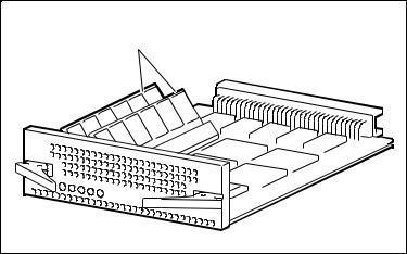
Figure 1-5 shows the Device I/O module.
Upper
Mounting 
Tab
Device Port 0
Connector
Device Port 1
Connector
Lower
Mounting 
Tab
SHR-1045
Figure 1-5. Device I/O module
The dual-channel device I/O module has two 68-pin VHDCI female connectors mounted on the front panel (see Figure 1– 5). The upper connector is the device port 0 connector. The lower connector is the device port 1 connector.
The device I/O module top and bottom guides properly align the module in the shelf and with the backplane connector at the back of the shelf. When you install the module the two spring mounting tabs expand and engage the shelf. The combination of the mounting tabs and the backplane connector ensures that the module is firmly seated.
The front edge of the internal circuit board in the device I/O module contains two blower-status LEDs (see Figure 1– 6). Under normal operating conditions, the LEDs are On. When there is a blower error or an over-temperature condition, they Flash. The upper LED displays the status of the left blower and the lower LED displays the status of the right blower. The blowers cool the device I/O module by drawing air in through the slots in the front and exhausting it out the rear of the shelf. Refer to the StorageWorks SBB Shelf I/O Module User’s Guide supplied with the device expansion shelf for a description of the blower status LEDs when troubleshooting a shelf-cooling problem.

Product Overview 1-11
Figure 1-6 shows the Device I/O module blower-status LEDs.
Left |
SCSI Bus |
Blower |
Address Switch S3 |
LED |
(Not Used) |
Right |
SCSI Bus |
Blower |
|
LED |
Termination |
|
Switch S4 |
|
SHR-1046 |
Figure 1-6. Device I/O module blower-status LEDs
NOTE: The SCSI bus address switch on the controller shelf device I/O module does not control the target addresses of the SBB slots in the device expansion shelves. This switch has been electrically disabled by design. Refer to the StorageWorks SBB Shelf I/O Module User’s Guide supplied with the device expansion shelf for a description of how to set the SCSI IDs in each shelf.
SCSI bus termination switch S4 configures the SCSI bus termination of the device expansion shelves in the RAID Array 3000 storage system. The proper settings for S4 are included in the Chapter 3, “Installation and Maintenance.”

1-12 RAID Array 3000 Controller Shelf Hardware User’s Guide
Host I/O Module
The controller shelf contains two identical host I/O modules
(see Figure 1– 7). The module located directly to the left of the device I/O module is designated as H1 and the module in the adjacent slot as H0. The host I/O module provides the interface between the host bus and the controller in the shelf.
Host Out 

Host In


CTR
UPS
SHR-1036
Figure 1-7. Host I/O module
The front panel of the host I/O module contains two 68-pin VHDCI SCSI connectors and two 9-pin D connectors. The SCSI connectors provide the SCSI bus connections between the adapter in the host system and the controllers in the Shelf. One of the 9-pin D connectors interfaces the UPS status signals to the controller. The other provides a serial connection between its respective controller, the shelf, and the SWCC configuration/maintenance PC.
The high-density SCSI connectors on the Host I/O module are designated Host In (bottom connector) and Host Out (top connector). Host In provides the SCSI connection for a one-to-four expansion shelf cabinet installation. Cable connections to multiple storage shelves are made through Trilink adapters.
Product Overview 1-13
In addition to the front panel connectors, the Host I/O module contains three passive differential SCSI bus terminators that terminate the SCSI bus from the host system. Termination is automatically disabled when a cable is connected to the Host Out connector. The UPS serial connector on the host I/O module (designated CTR 0 and CTR 1) provides shelf status information to the UPS.
NOTE: If you have only one SCSI cable connection to the host I/O module, you must connect the cable to the Host In connector. Do not use any external bus termination. The Host Out connector on the module is used for mid-bus connections in a multiple-host system configuration.
Shelf Cooling
The device I/O module ensures that the SBBs and controller shelf are at the proper operating temperature by monitoring the operational status of the blowers and sensing the ambient air temperature.
The two dual-speed blowers cool all the shelf components by drawing ambient air in through the front of the SBBs and exhausting it out the rear of the controller shelf. The blowers normally operate at low speed. Reduction of the airflow through the shelf or an increase in the ambient temperature may result in overheating, causing component failure or data corruption.
The device I/O module ambient temperature circuitry monitors the air flowing through the module. If the ambient temperature exceeds 90ºF + 36ºF
(32ºC + 2ºC), the circuitry:
■Turns on LED for both blowers.
■Causes both blowers to switch to the high-speed mode to increase airflow through the shelf.
When the I/O module circuitry detects a blower that is not operating or not operating at the correct RPM, this circuitry:
■Turns On an LED on the I/O module front panel that identifies the defective blower.
■Causes the operational blower to switch to the high-speed mode to increase airflow through the shelf, thereby maintaining the proper operating environment.
NOTE: The controller shelf power supply-status LEDs also display blower error conditions. However, they do not identify the defective blower, nor do they report ambient air temperature faults.

1-14 RAID Array 3000 Controller Shelf Hardware User’s Guide
Controller Shelf Power Supplies
The controller shelf has two interchangeable, air-cooled, 180 watt AC power supply SBBs (see Figure 1– 8) located in the left two SBB slots of the shelf. The power supplies provide redundant power if one of the units should malfunction. Each supply provides +5 and +12 VDC to power the RAID controllers, the host I/O modules, the device I/O module, and the blowers. The first power supply from the left edge of the shelf is designated as A and the second as B. The SBB front panel has an AC input power receptacle, a power supply status LED, and a shelf status LED.
SHR-1034
Figure 1-8. Power supply
UPS
The primary function of the UPS is to keep the entire storage system powered up to enable the controllers to flush cache to disks. The UPS also protects the storage system from problems associated with poor quality AC power or a complete loss of AC power. The UPS is normally mounted in a lower shelf slot in the cabinet using a custom set of mounting brackets.
 Loading...