


 Loading...
User Guide
hp StorageWorks
Modular Smart Array 1000 (MSA1000) Controller
First Edition (September 2003)
Part Number: 347281-001
This guide provides the user with information needed to use, replace and maintain the HP StorageWorks Modular Smart Array 1000 Controller.
Note: Documentation titled HP StorageWorks Modular SAN Array 1000 or HP StorageWorks Modular Smart Array 1000 both refer to the HP StorageWorks MSA1000.
© Copyright 2003 Hewlett-Packard Development Company, L.P.
Hewlett-Packard Company makes no warranty of any kind with regard to this material, including, but not limited to, the implied warranties of merchantability and fitness for a particular purpose. Hewlett-Packard shall not be liable for errors contained herein or for incidental or consequential damages in connection with the furnishing, performance, or use of this material.
This document contains proprietary information, which is protected by copyright. No part of this document may be photocopied, reproduced, or translated into another language without the prior written consent of Hewlett-Packard. The information contained in this document is subject to change without notice.
Hewlett-Packard Company shall not be liable for technical or editorial errors or omissions contained herein. The information is provided “as is” without warranty of any kind and is subject to change without notice. The warranties for Hewlett-Packard Company products are set forth in the express limited warranty statements for such products. Nothing herein should be construed as constituting an additional warranty.
Printed in the U.S.A.
MSA1000 Controller User Guide
First Edition (September 2003)
Part Number: 347281-001

Contents
About this Guide. . . . . . . . . . . . . . . . . . . . . . . . . . . . . . . . . . . . . . . . . . . . . . . . . . . .5
Overview. . . . . . . . . . . . . . . . . . . . . . . . . . . . . . . . . . . . . . . . . . . . . . . . . . . . . . . . . . . . . . . . . . 6 Intended Audience . . . . . . . . . . . . . . . . . . . . . . . . . . . . . . . . . . . . . . . . . . . . . . . . . . . . . . . 6 Related Documentation . . . . . . . . . . . . . . . . . . . . . . . . . . . . . . . . . . . . . . . . . . . . . . . . . . . 6 Conventions . . . . . . . . . . . . . . . . . . . . . . . . . . . . . . . . . . . . . . . . . . . . . . . . . . . . . . . . . . . . . . . 7 Document Conventions . . . . . . . . . . . . . . . . . . . . . . . . . . . . . . . . . . . . . . . . . . . . . . . . . . . 7 Text Symbols . . . . . . . . . . . . . . . . . . . . . . . . . . . . . . . . . . . . . . . . . . . . . . . . . . . . . . . . . . . 7 Equipment Symbols . . . . . . . . . . . . . . . . . . . . . . . . . . . . . . . . . . . . . . . . . . . . . . . . . . . . . . 8 Getting Help . . . . . . . . . . . . . . . . . . . . . . . . . . . . . . . . . . . . . . . . . . . . . . . . . . . . . . . . . . . . . . . 9 HP Technical Support . . . . . . . . . . . . . . . . . . . . . . . . . . . . . . . . . . . . . . . . . . . . . . . . . . . 10 HP Website. . . . . . . . . . . . . . . . . . . . . . . . . . . . . . . . . . . . . . . . . . . . . . . . . . . . . . . . . . . . 10 HP Authorized Reseller . . . . . . . . . . . . . . . . . . . . . . . . . . . . . . . . . . . . . . . . . . . . . . . . . . 10
1 MSA1000 Controller . . . . . . . . . . . . . . . . . . . . . . . . . . . . . . . . . . . . . . . . . . . . . . . .11
Components . . . . . . . . . . . . . . . . . . . . . . . . . . . . . . . . . . . . . . . . . . . . . . . . . . . . . . . . . . . . . . 11
MSA1000 Controller Display . . . . . . . . . . . . . . . . . . . . . . . . . . . . . . . . . . . . . . . . . . . . . 12
Array Accelerator (Battery-backed Cache) . . . . . . . . . . . . . . . . . . . . . . . . . . . . . . . . . . . 13
Array Accelerator Features . . . . . . . . . . . . . . . . . . . . . . . . . . . . . . . . . . . . . . . . 13
Array Accelerator Batteries . . . . . . . . . . . . . . . . . . . . . . . . . . . . . . . . . . . . . . . . . . . . . . . 14
Replacing the MSA1000 Controller Cache . . . . . . . . . . . . . . . . . . . . . . . . . . . . . . . . . . . 15
Replacing the Controller Cache Battery Pack . . . . . . . . . . . . . . . . . . . . . . . . . . . . . . . . . 18
Recovery ROM and ROM Cloning . . . . . . . . . . . . . . . . . . . . . . . . . . . . . . . . . . . . . . . . . . . . 23
Recovery ROM . . . . . . . . . . . . . . . . . . . . . . . . . . . . . . . . . . . . . . . . . . . . . . . . . . . . . . . . 23
ROM Cloning. . . . . . . . . . . . . . . . . . . . . . . . . . . . . . . . . . . . . . . . . . . . . . . . . . . . . . . . . . 23
MSA1000 Controller Indicators . . . . . . . . . . . . . . . . . . . . . . . . . . . . . . . . . . . . . . . . . . . . . . 24
Replacing the MSA1000 Controller . . . . . . . . . . . . . . . . . . . . . . . . . . . . . . . . . . . . . . . . . . . 26
Updating the Controller Firmware . . . . . . . . . . . . . . . . . . . . . . . . . . . . . . . . . . . . . . . . . . . . . 28
2 Controller Display Messages . . . . . . . . . . . . . . . . . . . . . . . . . . . . . . . . . . . . . . . . . .29
About the LCD Messages. . . . . . . . . . . . . . . . . . . . . . . . . . . . . . . . . . . . . . . . . . . . . . . . . . . . 30
MSA1000 Controller User Guide |
3 |

Contents
Error Messages . . . . . . . . . . . . . . . . . . . . . . . . . . . . . . . . . . . . . . . . . . . . . . . . . . . . . 30
Informational Messages. . . . . . . . . . . . . . . . . . . . . . . . . . . . . . . . . . . . . . . . . . . . . . . 30
User Input Messages . . . . . . . . . . . . . . . . . . . . . . . . . . . . . . . . . . . . . . . . . . . . . . . . . 30
Scrolling . . . . . . . . . . . . . . . . . . . . . . . . . . . . . . . . . . . . . . . . . . . . . . . . . . . . . . . . . . . . . . 31
User Input. . . . . . . . . . . . . . . . . . . . . . . . . . . . . . . . . . . . . . . . . . . . . . . . . . . . . . . . . . . . . 31
Deleting Messages . . . . . . . . . . . . . . . . . . . . . . . . . . . . . . . . . . . . . . . . . . . . . . . . . . . . . . 31
Redundancy Link Light . . . . . . . . . . . . . . . . . . . . . . . . . . . . . . . . . . . . . . . . . . . . . . . . . . 31
LCD Message Descriptions . . . . . . . . . . . . . . . . . . . . . . . . . . . . . . . . . . . . . . . . . . . . . . . . . . 32
A Regulatory Compliance Notices . . . . . . . . . . . . . . . . . . . . . . . . . . . . . . . . . . . . . . . .63
Regulatory Compliance Identification Numbers . . . . . . . . . . . . . . . . . . . . . . . . . . . . . . . 63
Federal Communications Commission Notice. . . . . . . . . . . . . . . . . . . . . . . . . . . . . . . . . 63
Modifications. . . . . . . . . . . . . . . . . . . . . . . . . . . . . . . . . . . . . . . . . . . . . . . . . . . . . . . 63
Cables . . . . . . . . . . . . . . . . . . . . . . . . . . . . . . . . . . . . . . . . . . . . . . . . . . . . . . . . . . . . 63
Canadian Notice (Avis Canadien) . . . . . . . . . . . . . . . . . . . . . . . . . . . . . . . . . . . . . . . . . . 64
European Union Notice . . . . . . . . . . . . . . . . . . . . . . . . . . . . . . . . . . . . . . . . . . . . . . . . . . 64
Japanese Notice . . . . . . . . . . . . . . . . . . . . . . . . . . . . . . . . . . . . . . . . . . . . . . . . . . . . . . . . 64
BSMI Notice . . . . . . . . . . . . . . . . . . . . . . . . . . . . . . . . . . . . . . . . . . . . . . . . . . . . . . . . . . 65
Laser Compliance. . . . . . . . . . . . . . . . . . . . . . . . . . . . . . . . . . . . . . . . . . . . . . . . . . . . . . . 65
Battery Replacement Notice . . . . . . . . . . . . . . . . . . . . . . . . . . . . . . . . . . . . . . . . . . . . . . 66
B Electrostatic Discharge. . . . . . . . . . . . . . . . . . . . . . . . . . . . . . . . . . . . . . . . . . . . . . .67
Grounding Methods . . . . . . . . . . . . . . . . . . . . . . . . . . . . . . . . . . . . . . . . . . . . . . . . . . . . . . . . 68
Index . . . . . . . . . . . . . . . . . . . . . . . . . . . . . . . . . . . . . . . . . . . . . . . . . . . . . . . . . . .69
4 |
MSA1000 Controller User Guide |

About This
Guide
This user guide provides information to help you:
■Operate the MSA1000 controller
■Replace the MSA1000 controller “About this Guide” topics include:
■Overview, page 6
■Conventions, page 7
■Getting Help, page 9
MSA1000 Controller User Guide |
5 |

About this Guide
Overview
This section covers the following topics:
■Intended Audience
■Related Documentation
Intended Audience
This book is intended for use by administrators with a moderate amount of SAN-management experience.
Related Documentation
In addition to this guide, refer to the HP StorageWorks MSA1000 Installation Guide that ships with this system.
6 |
MSA1000 Controller User Guide |

About this Guide
Conventions
Conventions consist of the following:
■Document Conventions
■Text Symbols
■Equipment Symbols
Document Conventions
The document conventions included in Table 1 apply in most cases.
Table 1: Document Conventions |
|
|
|
|
|
Element |
Convention |
|
Cross-reference links |
Figure 1 |
|
|
|
|
Key and field names, menu items, |
Bold |
|
buttons, and dialog box titles |
|
|
|
|
|
File names, application names, and text |
Italics |
|
emphasis |
|
|
|
|
|
User input, command and directory |
Monospace font |
|
names, and system responses (output |
COMMAND NAMES are uppercase |
|
and messages) |
||
monospace font unless they are case |
||
|
sensitive |
|
|
|
|
Variables |
<monospace, italic font> |
|
|
|
|
Website addresses |
Underlined sans serif font text: |
|
|
http://www.hp.com |
|
|
|
Text Symbols
The following symbols may be found in the text of this guide. They have the following meanings:
WARNING: Text set off in this manner indicates that failure to follow directions in the warning could result in bodily harm or death.
MSA1000 Controller User Guide |
7 |
About this Guide
Caution: Text set off in this manner indicates that failure to follow directions could result in damage to equipment or data.
Note: Text set off in this manner presents commentary, sidelights, or interesting points of information.
Equipment Symbols
The following equipment symbols may be found on hardware for which this guide pertains. They have the following meanings:
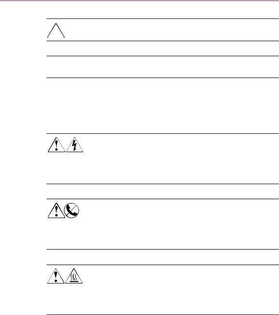
Any enclosed surface or area of the equipment marked with these symbols indicates the presence of electrical shock hazards. Enclosed area contains no operator serviceable parts.
WARNING: To reduce the risk of personal injury from electrical shock hazards, do not open this enclosure.
Any RJ-45 receptacle marked with these symbols indicates a network interface connection.
WARNING: To reduce the risk of electrical shock, fire, or damage to the equipment, do not plug telephone or telecommunications connectors into this receptacle.
Any surface or area of the equipment marked with these symbols indicates the presence of a hot surface or hot component. Contact with this surface could result in injury.
WARNING: To reduce the risk of personal injury from a hot component, allow the surface to cool before touching.
8 |
MSA1000 Controller User Guide |
About this Guide
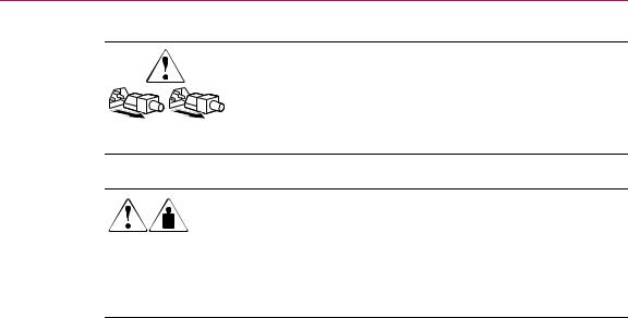
Power supplies or systems marked with these symbols indicate the presence of multiple sources of power.
WARNING: To reduce the risk of personal injury from electrical shock, remove all power cords to completely disconnect power from the power supplies and systems.
Any product or assembly marked with these symbols indicates that the component exceeds the recommended weight for one individual to handle safely.
WARNING: To reduce the risk of personal injury or damage to the equipment, observe local occupational health and safety requirements and guidelines for manually handling material.
Getting Help
If you still have a question after reading this guide, contact an HP authorized service provider or access our website: http://www.hp.com.
MSA1000 Controller User Guide |
9 |

About this Guide
HP Technical Support
In North America, call technical support at 1-800-652-6672, available 24 hours a day, 7 days a week.
Note: For continuous quality improvement, calls may be recorded or monitored.
Outside North America, call technical support at the nearest location. Telephone
numbers for worldwide technical support are listed on the HP website under support: http://www.hp.com.
Be sure to have the following information available before calling:
■Technical support registration number (if applicable)
■Product serial numbers
■Product model names and numbers
■Applicable error messages
■Operating system type and revision level
■Detailed, specific questions
HP Website
The HP website has the latest information on this product, as well as the latest drivers. Access storage at: www.hp.com/go/msa1000. From this website, select the
appropriate product or solution.
HP Authorized Reseller
For the name of your nearest HP Authorized Reseller:
■In the United States, call 1-800-345-1518
■In Canada, call 1-800-263-5868
■Elsewhere, see the HP website for locations and telephone numbers: http://www.hp.com.
10 |
MSA1000 Controller User Guide |
MSA1000 Controller |
1 |
|
Components
The MSA1000 Controller is a drive array controller specifically designed for installation in the MSA1000. The MSA1000 comes equipped with one MSA1000 Controller installed. An additional controller for redundancy can be purchased separately.
To ensure uninterrupted service, two copies of the controller firmware are stored in Read Only Memory (ROM) on the controller. See the “Recovery ROM” and “ROM Cloning” sections for more information.
Additional information about the following topics is included in this section:
■MSA1000 Controller Display
■Array Accelerator (Battery-backed Cache)
MSA1000 Controller User Guide |
11 |
MSA1000 Controller
MSA1000 Controller Display
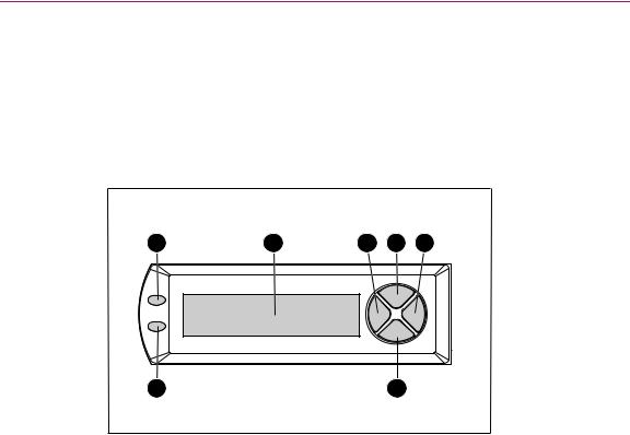
Each array controller in an MSA1000 contains an integrated Liquid Crystal Display (LCD). This module is used for displaying informational and error messages, showing the status of the module, and for providing user input when required. Traditional Power-On Self-Test (POST) messages issued by PCI-based array controllers have been combined with runtime event notification messages to create a new set of controller display messages.
1 |
2 |
3 |
4 |
5 |
7 |
6 |
Figure 1: Controller display
\ |
|
Controller Display |
Description |
1 |
Fault indicator (amber) |
|
|
2 |
Display |
|
|
3 |
Left push button |
|
|
4 |
Up push button |
|
|
5 |
Right push button |
|
|
6 |
Down push button |
|
|
7 |
Redundancy Link indicator (green) |
|
|
For more information about the MSA1000 Controller display, see the “Controller Display Messages” chapter.
12 |
MSA1000 Controller User Guide |

MSA1000 Controller
Array Accelerator (Battery-backed Cache)
The Array Accelerator is a high-performance, upgradeable 256-MB SDRAM DIMM read/write battery-backed cache that can increase performance in database and fault-tolerant configurations. It performs both protected posted-write caching and read-ahead caching, allowing data to be accessed much faster than from disk storage.
In protected posted-write caching, data is written to the cache memory on the Array Accelerator rather than directly to the drives. Later, when the MSA1000 storage system is idle, the controller writes the cached data to the drive array.
The read-ahead cache detects sequential accesses to the array, reads ahead data, and stores the data in the cache until the next read access arrives. If the data is of a sequential nature, the data can be loaded immediately into memory, avoiding the latency of a disk access.
If the MSA1000 Controller fails before cached data is stored on the disk, the Array Accelerator and its integrated batteries may be removed from one MSA1000 Controller and installed on a replacement controller. Any data in the Array Accelerator that has not been written to the hard drive will be transferred to the replacement MSA1000 Controller.
Array Accelerator Features
Other features of the Array Accelerator:
■Mounted on a removable daughterboard (allows stored data to be moved to another controller if the original controller fails)
■Backed up with replaceable batteries
■Upgradable to 512 MB (256 MB per controller)
■Adjustable read/write ratio - usually set during array configuration but can be changed at any time
■16-bit Error Checking and Correcting (ECC) SDRAM memory
ECC detects and corrects all single-bit memory errors. It also detects all two-bit memory errors in any position, and most threeand four-bit memory errors in a single SDRAM. With ECC, an entire memory chip can also fail without data loss. This provides a high level of data integrity by ensuring the correction of common memory errors without affecting performance.
MSA1000 Controller User Guide |
13 |

MSA1000 Controller
Array Accelerator Batteries
The Array Accelerator has two rechargeable and replaceable Nickel Metal Hydride (NiMH) battery packs. Under normal operating conditions, these should last for three years before replacement is necessary. They are continuously recharged via a “trickle” charging process whenever the MSA1000 storage system is powered on.
The battery packs protect data on the Array Accelerator against equipment failure or power outage for up to four continuous days.
Note: Temperature, age, and cache size may affect battery life.
This also applies if the Array Accelerator is removed from the MSA1000 Controller. When power is restored to the MSA1000 storage system, an initialization process writes the preserved data to the disk drives. This is particularly important for data that has been cached by a posted-write operation, but has not yet been written to the hard drives.
Note: The batteries on a new MSA1000 Controller may be discharged when the board is first installed. In this case, a Power-On Self-Test (POST) message will be displayed on the controller display panel when the controller is powered on, indicating that the Array Accelerator is temporarily disabled. No action is required on your part, since the internal circuitry will automatically recharge the batteries. Recharging the batteries can take up to 4 hours. The MSA1000 Controller will function properly during this time, although without the performance advantage of the Array Accelerator. When the batteries are charged to 90 percent of their capacity, the Array Accelerator is automatically enabled.
Depending on the status of the array accelerator, including a low battery charge, informational or error messages may be displayed on the controller’s LCD panel. For a listing of cache module LCD messages, see the definitions for LCD messages 60 through 79 in the “Controller Display Messages” chapter.
14 |
MSA1000 Controller User Guide |
MSA1000 Controller
Replacing the MSA1000 Controller Cache
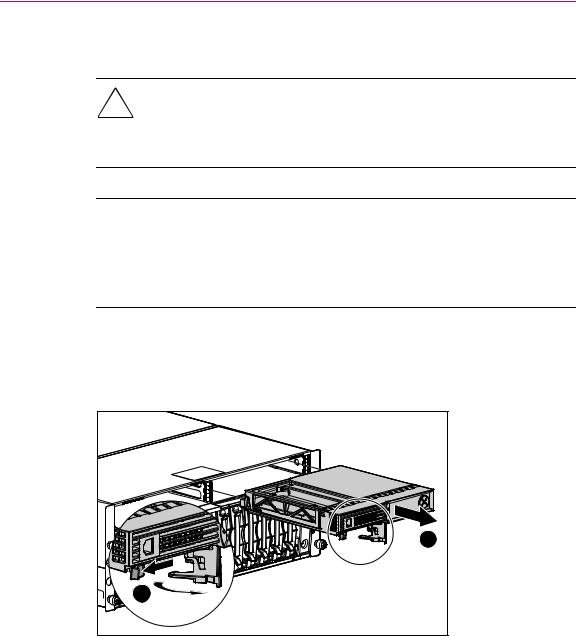
Caution: It is important to follow these instructions when replacing components in the MSA1000. If the procedure is done improperly, it is possible to lose data or damage equipment. Refer to Appendix B, “Electrostatic Discharge,” for important information on using the proper procedures.
Note: If your system is equipped with a single controller, and you must replace the controller cache, you must power down the system first. If your system is equipped with two controllers, and you want to replace a failed cache module with another of the same size, you can replace the module while the system is running. If your system is equipped with two controllers, and you are replacing the cache module with a module of a different size, you must power down the system first, and then change the cache module on both controllers at the same time.
1.Press the controller’s thumb latch and pull the latch handle towards you 1. See Figure 2.
2.Remove the MSA1000 Controller by pulling it straight out of the chassis 2.
2 |
1 |
Figure 2: Removing the controller
MSA1000 Controller User Guide |
15 |

MSA1000 Controller
3.As illustrated in Figure 3, unlatch the controller cover clips 1 on the rear of the controller and then raise the cover 2.
Note: The controller in Figure 3 has been rotated so the side and rear of the controller are visible.
4.Simultaneously unlatch the clips that are holding the MSA1000 Controller cache in place 3.
5.Carefully pull the cache away from the controller board 4.
2 |
1 |
3 |
4 |
Figure 3: Removing the cache module
16 |
MSA1000 Controller User Guide |

MSA1000 Controller
6.Install the new MSA1000 Controller cache by sliding the new MSA1000 Controller cache into the controller 1. Be sure the side latches are fully engaged 2. See Figure 4.
2 |
1 |
Figure 4: Installing the cache module
7.Push the controller in as far as it will go 1; press the latch inward until it is flush against the front panel 2. See Figure 5.
1 |
2 |
Figure 5: Installing the controller
MSA1000 Controller User Guide |
17 |

MSA1000 Controller
Replacing the Controller Cache Battery Pack
WARNING: There is a risk of explosion, fire, or personal injury if the battery pack is replaced incorrectly or mistreated. To reduce the risk:
■Do not attempt to recharge the battery outside of the controller.
■Do not expose to water, or to temperatures higher than 60°C.
■Do not abuse, disassemble, crush, puncture, short external contacts, or dispose of in fire or water.
■Replace only with the spare designated for this product.
■Array Accelerator battery disposal should comply with local regulations. Alternatively, return them by established parts return methods to HewlettPackard Corporation for disposal.
Caution: It is important to follow these instructions when replacing components in the MSA1000. If the procedure is done improperly, it is possible to lose data or damage equipment. Refer to the “Electrostatic Discharge” appendix for important information on using the proper procedures.
To remove the old NiMH battery pack:
1.Remove the MSA1000 Controller Cache, as instructed in the previous section, “Replacing the MSA1000 Controller Cache.”
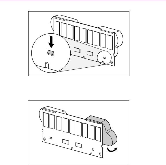
2.Push down on the bottom clip of the battery pack, attached near the lower corner of the Array Accelerator.
See Figure 6 for an illustration.
18 |
MSA1000 Controller User Guide |
MSA1000 Controller
Figure 6: Bottom clip on battery pack
3.Swing the battery pack away from the Array Accelerator to about a 30-degree angle.
Figure 7: Angling the battery pack
MSA1000 Controller User Guide |
19 |
MSA1000 Controller
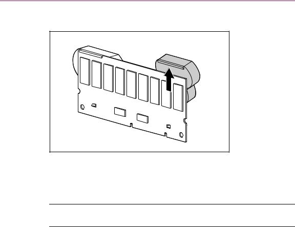
4. Lift the pack upward to unhook the top of the battery pack.
Figure 8: Removing the battery pack
Wait about 15 seconds after removing the old battery packs to allow the battery charge monitor to reset.
Note: Repeat the replacement procedure for any batteries that were installed at the same time as the batteries that were removed.
20 |
MSA1000 Controller User Guide |
MSA1000 Controller
5.Install the new NiMH battery pack by hooking the top of the battery pack to the top of the Array Accelerator with the pack held at a 30-degree angle to the plane of the Array Accelerator board.
See Figure 9 for an illustration.
Figure 9: Installing the battery pack
MSA1000 Controller User Guide |
21 |
MSA1000 Controller
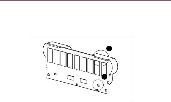
6.After the pack is hooked in position, swing the pack downward making sure the bottom clip and two pegs line up with the holes in the Array Accelerator.
7.Make sure that the top hook 1 and bottom clip 2 on the battery pack are securely attached to the Array Accelerator.
1
2
Figure 10: Securing the battery pack
8.Installation of the new battery pack is complete. Repeat for the second battery on this battery pack.
22 |
MSA1000 Controller User Guide |
Loading...