


HP Stream Laptop PC 14
* Model numbers: 14-ax0XX
Maintenance and Service Guide IMPORTANT! This document is intended for HP authorized service providers only.
© Copyright 2016 HP Development Company,
L.P.
Bluetooth is a trademark owned by its proprietor and used by HP Inc. under license. Intel and Celeron are trademarks of Intel Corporation in the U.S. and other countries. Microsoft and Windows are U.S. registered trademarks of the Microsoft group of companies. SD Logo is a trademark of its proprietor.
The information contained herein is subject to change without notice. The only warranties for HP products and services are set forth in the express warranty statements accompanying such products and services. Nothing herein should be construed as constituting an additional warranty. HP shall not be liable for technical or editorial errors or omissions contained herein.
First Edition: August 2016
Document Part Number: 902530-001
Product notice
This guide describes features that are common to most models. Some features may not be available on your computer.
Not all features are available in all editions of Windows. This computer may require upgraded and/or separately purchased hardware, drivers, and/or software to take full advantage of Windows functionality. See http://www.microsoft.com for details.
Software terms
By installing, copying, downloading, or otherwise using any software product preinstalled on this computer, you agree to be bound by the terms of the HP End User License Agreement (EULA). If you do not accept these license terms, your sole remedy is to return the entire unused product (hardware and software) within 14 days for a refund subject to the refund policy of your place of purchase.
For any further information or to request a full refund of the computer, please contact your local point of sale (the seller).

Safety warning notice
 WARNING! To reduce the possibility of heat-related injuries or of overheating the device, do not place the device directly on your lap or obstruct the device air vents. Use the device only on a hard, flat surface. Do not allow another hard surface, such as an adjoining optional printer, or a soft surface, such as pillows or rugs or clothing, to block airflow. Also, do not allow the AC adapter to contact the skin or a soft surface, such as pillows or rugs or clothing, during operation. The device and the AC adapter comply with the user-accessible surface temperature limits de ned by the International Standard for Safety of Information Technology Equipment (IEC 60950-1).
iii
iv Safety warning notice

Table of contents
1 Product description ....................................................................................................................................... |
1 |
2 External component dent c t on .................................................................................................................. |
3 |
Display .................................................................................................................................................................... |
3 |
Left side ................................................................................................................................................................. |
4 |
Right side ............................................................................................................................................................... |
5 |
Front ....................................................................................................................................................................... |
5 |
Top .......................................................................................................................................................................... |
6 |
TouchPad ............................................................................................................................................. |
6 |
Lights ................................................................................................................................................... |
7 |
Button .................................................................................................................................................. |
8 |
Keys ..................................................................................................................................................... |
9 |
Using the action keys ........................................................................................................................ |
10 |
Labels ................................................................................................................................................................... |
11 |
3 Illustrated parts catalog .............................................................................................................................. |
13 |
Computer major components .............................................................................................................................. |
13 |
Rubber Kit ............................................................................................................................................................ |
15 |
Display assembly components ............................................................................................................................ |
16 |
Miscellaneous parts ............................................................................................................................................. |
17 |
4 Removal and replacement procedures preliminary requirements .................................................................... |
18 |
Tools required ...................................................................................................................................................... |
18 |
Service considerations ......................................................................................................................................... |
18 |
Plastic parts ....................................................................................................................................... |
18 |
Cables and connectors ...................................................................................................................... |
18 |
Grounding guidelines ........................................................................................................................................... |
19 |
Electrostatic discharge damage ........................................................................................................ |
19 |
Packaging and transporting guidelines .......................................................................... |
20 |
Workstation guidelines ................................................................................ |
20 |
5 Removal and replacement procedures for Authorized Service Provider parts ................................................... |
22 |
Component replacement procedures .................................................................................................................. |
22 |
Bottom cover ..................................................................................................................................... |
23 |
Battery ............................................................................................................................................... |
24 |
Memory module ................................................................................................................................ |
25 |
v
WLAN module .................................................................................................................................... |
26 |
RTC battery ........................................................................................................................................ |
28 |
Heat sink ............................................................................................................................................ |
29 |
Speakers ............................................................................................................................................ |
31 |
System board .................................................................................................................................... |
32 |
TouchPad ........................................................................................................................................... |
34 |
Display assembly ............................................................................................................................... |
35 |
Power button board .......................................................................................................................... |
41 |
Power connector cable ...................................................................................................................... |
42 |
Keyboard/top cover ........................................................................................................................... |
43 |
6 Using Setup Utility (BIOS) ............................................................................................................................. |
44 |
Starting Setup Utility (BIOS) ................................................................................................................................ |
44 |
Updating Setup Utility (BIOS) .............................................................................................................................. |
44 |
Determining the BIOS version ........................................................................................................... |
44 |
Downloading a BIOS update .............................................................................................................. |
45 |
7 pec c t ons .............................................................................................................................................. |
46 |
Computer speci cations ...................................................................................................................................... |
46 |
35.56-cm (14.0-in), HD display speci cations .................................................................................................... |
47 |
8 Backing up, restoring, and recovering ........................................................................................................... |
48 |
Creating recovery media and backups ................................................................................................................ |
48 |
Creating HP Recovery media (select products only) ......................................................................... |
48 |
Using Windows tools ........................................................................................................................................... |
49 |
Restore and recovery ........................................................................................................................................... |
50 |
Recovering using HP Recovery Manager ........................................................................................... |
50 |
What you need to know before you get started ............................................................. |
50 |
Using the HP Recovery partition (select products only) ................................................. |
51 |
Using HP Recovery media to recover .............................................................................. |
51 |
Changing the computer boot order ................................................................................ |
52 |
Removing the HP Recovery partition (select products only) ......................................... |
53 |
9 Using HP PC Hardware Diagnostics (UEFI) ....................................................................................................... |
54 |
Downloading HP PC Hardware Diagnostics (UEFI) to a USB device .................................................................... |
54 |
10 Power cord set requirements ...................................................................................................................... |
56 |
Requirements for all countries ............................................................................................................................ |
56 |
Requirements for speci c countries and regions ................................................................................................ |
56 |
vi
11 Recycling .................................................................................................................................................. |
58 |
Index ............................................................................................................................................................. |
59 |
vii
viii

1Product description
Category |
Description |
|
|
Product Name |
HP Stream Laptop PC |
|
Model numbers: 14-ax0XX |
|
|
Processor |
Intel Celeron® N3060 (1.6 GHz, turbo up to 2.48 GHz), 1600 MHz/2 MB L2 cache), dual core, 4 W |
|
Intel Celeron N3050 (1.6 GHz, turbo up to 2.16 GHz), 1600 MHz/2 MB L2 cache), dual core, 4 W |
|
|
Chipset |
Integrated SoC |
|
|
Graphics |
Internal graphics |
|
Intel HD Graphics 400 (N3060 processor) |
|
Intel HD Graphics (N3050 processor) |
|
Support for DX12, HD decode, and HDMI |
|
|
Panel |
16:9 ultra-wide aspect ratio |
|
14.0-in (1366×768), BrightView, high-de nition (HD), light-emitting diode (LED), slim 3.0 mm, eDP, 220 nits |
|
|
Memory |
On-board system memory |
|
● DDR3L-1600MHz single channel support |
|
● Supports up to 2 GB maximum on-board system memory |
|
One SODIMM slot-non-accessible/non-upgradeable |
|
● DDR3L-1600MHz single channel support |
|
● Supports up to 4 GB maximum system memory |
|
|
Hard drive |
eMMC con ur t on |
|
32 MB |
|
|
Optical drive |
External, 9.5-mm tray load, SATA, USB, DVD±RW DL SuperMulti Drive |
|
|
Camera and |
HP Webcam: VGA camera -indicator light, USB 2.0, 640×480 by 24 frames per second |
microphone |
Single digital microphone |
|
|
|
HP Noise Cancellation enabled |
|
|
Audio |
DTS Studio Sound |
|
Dual speakers |
|
|
Wireless |
Integrated Wireless options with dual antennas (M.2/PCIe) |
|
Intel Dual Band Wireless-AC 7265 802.11 AC 2x2 WiFi + BT 4.2 Combo Adapter (non-vPro) |
|
Compatible with iracast-certi ed devices |
|
|
External card |
HP Multi-Format Digital Media Card Reader |
expansion |
Support for SD/SDHC/SDXC |
|
|
|
Push-pull insertion/removal |
|
|
1

Category |
Description |
|
|
Internal card |
One M.2 card slot for WLAN |
expansion |
|
|
|
Ports |
AC Smart Pin adapter plug |
|
Combo audio-out (headphone)/audio-in (microphone) jack |
|
igh-de nition multimedia interface (HDMI) v.1.4, supporting 1920×1080 at 60 Hz |
|
USB 3.0 (2) |
|
USB 2.0 (1) |
|
|
Keyboard/pointing |
Keyboard |
devices |
Full-size, textured island keyboard (no numeric keypad) |
|
|
|
TouchPad requirements |
|
TouchPad with image sensor |
|
Taps enabled as default |
|
Multitouch gestures enabled |
|
Default on for 2- nger scroll, pinch, rotate, 2- nger click, 3- nger flick |
|
|
Power |
Battery |
requirements |
3-cell, 41-WHr, Li-ion battery |
|
|
|
AC adapter |
|
45-W |
|
|
Security |
Kensington Security Lock |
|
Support for Trust Platfom Module (TPM) 2.0 |
|
|
Operating system |
Preinstalled |
|
Windows 10 |
|
For Developed Market (ML) |
|
Microsoft Windows 10 Home Entry Notebook with OneDrive |
|
Microsoft Windows 10 Home Entry Notebook |
|
For Emerging Market (EM/SL) |
|
Microsoft Windows 10 Home Entry Notebook with OneDrive |
|
Microsoft Windows 10 Home Entry Notebook |
|
|
Serviceability |
End user replaceable part |
|
AC adapter |
|
|
2Chapter 1 Product description
2 External component dent c t on
Display
Component |
Description |
|
|
|
|
(1) |
Camera light |
On: The camera is in use. |
|
|
|
(2) |
Camera |
Allows you to video chat, record video, and record still images. |
|
|
|
(3) |
Internal microphone |
Records sound. |
|
|
|
(4) |
WLAN antennas* (1 or 2 depending on model) |
Send and receive wireless signals to communicate with wireless local |
|
|
area networks (WLANs). |
*The antennas are not visible from the outside of the computer, and antenna location varies. For optimal transmission, keep the areas immediately around the antennas free from obstructions.
For wireless regulatory notices, see the section of the Regulatory, Safety, and Environmental Notices that applies to your country or region.
To access this guide:
▲Select the Start button, select All apps (required on some products), select HP Help and Support, and then select HP Documentation.
Display 3
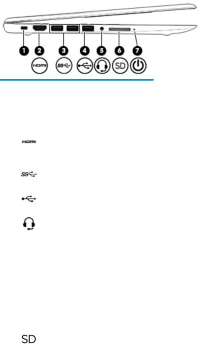
Left side
Component |
|
Description |
|
|
|
|
|
(1) |
Security cable slot |
Attaches an optional security cable to the computer. |
|
|
|
NOTE: The security cable is designed to act as a deterrent, but |
|
|
|
it may not prevent the computer from being mishandled or |
|
|
|
stolen. |
|
|
|
|
|
(2) |
HDMI port |
Connects an optional video or audio device, such as a high- |
|
|
|
de |
nition television, any compatible digital or audio component, |
|
|
or a high-speed igh- e nition Multimedia Interface (HDMI) |
|
|
|
device. |
|
|
|
|
|
(3) |
USB 3.0 ports (2) |
Connect an optional USB device, such as a keyboard, mouse, |
|
|
|
external drive, printer, scanner or USB hub. |
|
|
|
|
|
(4) |
USB 2.0 port |
Connects an optional USB device, such as a keyboard, mouse, |
|
|
|
external drive, printer, scanner or USB hub. |
|
|
|
|
|
(5) |
Audio-out (headphone)/Audio-in (microphone) |
Connects optional powered stereo speakers, headphones, |
|
|
combo jack |
earbuds, a headset, or a television audio cable. Also connects an |
|
|
|
optional headset microphone. This jack does not support |
|
|
|
optional standalone microphones. |
|
|
|
WARNING! To reduce the risk of personal injury, adjust the |
|
|
|
volume before putting on headphones, earbuds, or a headset. |
|
|
|
For additional safety information, refer to the Regulatory, |
|
|
|
Safety, and Environmental Notices. |
|
|
|
To access this guide: |
|
|
|
▲ Select the Start button, select All apps (required on some |
|
|
|
|
products), select HP Help and Support, and then select HP |
|
|
|
Documentation. |
|
|
NOTE: When a device is connected to the jack, the computer |
|
|
|
speakers are disabled. |
|
|
|
|
|
(6) |
Memory card reader |
Reads optional memory cards that enable you to store, manage, |
|
|
|
share, or access information. |
|
|
|
To insert a card: |
|
|
|
1. |
Hold the card label-side up, with connectors facing the |
|
|
|
computer. |
|
|
2. |
Insert the card into the memory card reader, and then |
|
|
|
press in on the card until it is rmly seated. |
To remove a card:
4 Chapter 2 External component identi cation

Component |
|
Description |
|
|
|
|
|
|
|
▲ |
Pull the card out of the memory card reader. |
|
|
|
|
(7) |
Power light |
● |
On: The computer is on. |
|
|
● |
Blinking: The computer is in the Sleep state, a power- |
|
|
|
saving state. The computer shuts o power to the display |
|
|
|
and other unneeded components. |
|
|
● |
The computer is o or in Hibernation. Hibernation is a |
|
|
|
power-saving state that uses the least amount of power. |
|
|
|
|
Right side
Component |
|
Description |
|
|
|
|
|
(1) |
AC adapter and battery light |
● |
White: The AC adapter is connected and the battery is fully |
|
|
|
charged. |
|
|
● |
Blinking white: The AC adapter is disconnected and the |
|
|
|
battery has reached a low battery level. |
|
|
● |
Amber: The AC adapter is connected and the battery is |
|
|
|
charging. |
|
|
● |
The battery is not charging. |
|
|
|
|
(2) |
Power connector |
Connects an AC adapter. |
|
Front
Component |
Description |
|
|
Speakers (2) |
Produce sound. |
|
|
Right side |
5 |

Top
TouchPad
Component |
|
Description |
|
|
|
(1) |
TouchPad zone |
Reads your nger gestures to move the pointer or activate items |
|
|
on the screen. |
|
|
|
(2) |
Left TouchPad button |
Functions like the left button on an external mouse. |
|
|
|
(3) |
Right TouchPad button |
Functions like the right button on an external mouse. |
|
|
|
6 Chapter 2 External component identi cation
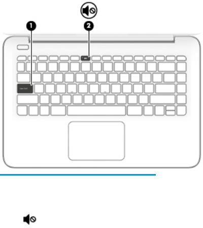
Lights
Component |
|
Description |
|
|
|
|
|
(1) |
Caps lock light |
On: Caps lock is on, which switches the key input to all capital |
|
|
|
letters. |
|
|
|
|
|
(2) |
Mute light |
● |
Amber: Computer sound is o . |
|
|
● |
Computer sound is on. |
|
|
|
|
Top 7
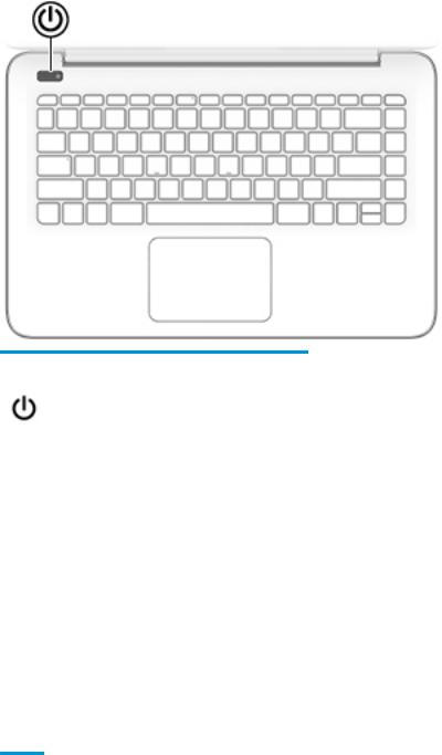
Button
Component |
Description |
|
|
|
|
Power button |
● |
When the computer is o , press the button to turn on the |
|
|
computer. |
|
● |
When the computer is on, press the button briefly to initiate |
|
|
Sleep. |
|
● |
When the computer is in the Sleep state, press the button briefly |
|
|
to exit Sleep. |
|
● |
When the computer is in Hibernation, press the button briefly to |
|
|
exit Hibernation. |
|
CAUTION: Pressing and holding down the power button results in the |
|
|
loss of unsaved information. |
|
|
If the computer has stopped responding and shutdown procedures are |
|
|
ine |
ective, press and hold the power button down for at least 5 |
|
seconds to turn o the computer. |
|
|
To learn more about your power settings, see your power options. |
|
|
▲ |
Type power in the taskbar search box, and then select Power & |
sleep settings.
‒ or –
Right-click the Start button, and then select Power Options.
8 Chapter 2 External component identi cation

Keys
Component |
|
Description |
|
|
|
(1) |
esc key |
Displays system information when pressed in combination with |
|
|
the fn key. |
|
|
|
(2) |
fn key |
Executes speci c functions when pressed in combination with |
|
|
the esc key. |
|
|
|
(3) |
Windows key |
Opens the Start menu. |
|
|
NOTE: Pressing the Windows key again will close the Start |
|
|
menu. |
|
|
|
(4) |
Action keys |
Execute frequently used system functions. |
|
|
|
Top 9

Using the action keys
●An action key performs an assigned function.
●The icon on each action key illustrates the function for that key.
Icon |
Description |
|
|
|
Opens the Get started app. |
|
|
|
Decreases the screen brightness incrementally as long as you hold down the key. |
|
|
|
Increases the screen brightness incrementally as long as you hold down the key. |
|
|
|
Switches the screen image between display devices connected to the system. For example, if a monitor is |
|
connected to the computer, repeatedly pressing this key alternates the screen image from the computer |
|
display to the monitor display to a simultaneous display on both the computer and the monitor. |
|
|
|
Mutes or restores speaker sound. |
|
|
|
Decreases speaker volume incrementally while you hold down the key. |
|
|
|
Increases speaker volume incrementally while you hold down the key. |
|
|
|
Plays the previous track of an audio CD or the previous section of a DVD or a Blu-ray Disc (BD). |
|
|
|
Starts, pauses, or resumes playback of an audio CD, a DVD, or a BD. |
|
|
|
Plays the next track of an audio CD or the next section of a DVD or a BD. |
|
|
|
Turns the airplane mode and wireless feature on or o . |
|
NOTE: The airplane mode key is also referred to as the wireless button. |
|
NOTE: A wireless network must be set up before a wireless connection is possible. |
|
|
10 Chapter 2 External component identi cation
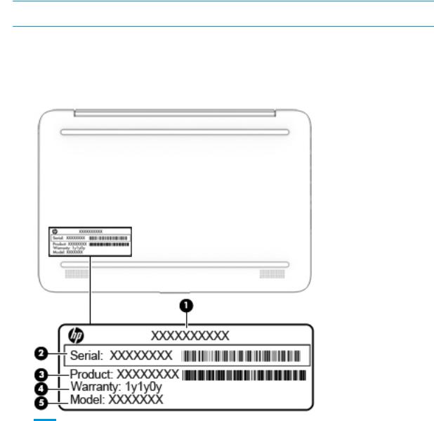
Labels
The labels affixed to the computer provide information you may need when you troubleshoot system problems or travel internationally with the computer.
 IMPORTANT: Check the following locations for the labels described in this section: the bottom of the computer, inside the battery bay, under the service door, or on the back of the display.
●Service label—Provides important information to identify your computer. When contacting support, you will probably be asked for the serial number, and possibly for the product number or the model number. Locate these numbers before you contact support.
Your service label will resemble one of the examples shown below. Refer to the illustration that most closely matches the service label on your computer.
Item |
Description |
Function |
|
|
|
(1) |
Product name |
This is the product name affixed to the front of the computer. |
|
|
|
(2) |
Serial number |
This is an alphanumeric identi er that is unique to each product. |
|
|
|
(3) |
Product number |
This number provides speci c information about the product's hardware |
|
|
components. The part number helps a service technician to determine what |
|
|
components and parts are needed. |
|
|
|
Labels 11

Item |
Description |
Function |
|
|
|
(4) |
Warranty period |
This number describes the duration of the warranty period for the computer. |
|
|
|
(5) |
Model description |
This is the alphanumeric identi er used to locate documents, drivers, and |
|
|
support for the computer. |
|
|
|
●Regulatory label(s)—Provide(s) regulatory information about the computer.
●Wireless certi cation label(s)—Provide(s) information about optional wireless devices and the approval markings for the countries or regions in which the devices have been approved for use.
12 Chapter 2 External component identi cation

3Illustrated parts catalog
 NOTE: HP continually improves and changes product parts. For complete and current information on supported parts for your computer, go to http://partsurfer.hp.com, select your country or region, and then follow the on-screen instructions.
Computer major components
Computer major components 13
 Loading...