


HP StorageWorks 70 Modular Smart Array Enclosure
user guide
Part number: 434893–002 First edition: February 2007
Legal and notice information
© Copyright 2007 Hewlett-Packard Development Company, L.P.
The information contained herein is subject to change without notice. The only warranties for HP products and services are set forth in the express warranty statements accompanying such products and services. Nothing herein should be construed as constituting an additional warranty. HP shall not be liable for technical or editorial errors or omissions contained herein.
Microsoft and Windows are U.S. registered trademarks of Microsoft Corporation.

Contents
About this guide |
. . . . . . . . . . . . . . . . . . . . . . . . . . |
7 |
Intended audience . . . . . . . . . . . . . . . . . . . . . . . . . . . . . . . . . . . . . . |
7 |
|
Document conventions and symbols . . . . . . . . . . . . . . . . . . . . . . . . . . . . . . |
7 |
|
HP technical support . . . . . . . . . . . . . . . . . . . . . . . . . . . . . . . . . . . . . |
8 |
|
Customer self repair . . . . . . . . . . . . . . . . . . . . . . . . . . . . . . . . . . . . . |
8 |
|
Product warranties . . . . . . . . . . . . . . . . . . . . . . . . . . . . . . . . . . . . . . |
8 |
|
Subscription service . . . . . . . . . . . . . . . . . . . . . . . . . . . . . . . . . . . . . |
8 |
|
HP websites . . . . . . . . . . . . . . . . . . . . . . . . . . . . . . . . . . . . . . . . . |
8 |
|
Documentation feedback . . . . . . . . . . . . . . . . . . . . . . . . . . . . . . . . . . . |
9 |
|
1 Identifying the components . . . . . . . . . . . . . . . . . . . . . |
11 |
Front panel components . . . . . . . . . . . . . . . . . . . . . . . . . . . . . . . . . . . |
11 |
Front panel LEDs . . . . . . . . . . . . . . . . . . . . . . . . . . . . . . . . . . . . . . . |
11 |
Rear panel components . . . . . . . . . . . . . . . . . . . . . . . . . . . . . . . . . . . |
12 |
Rear panel LEDs and buttons . . . . . . . . . . . . . . . . . . . . . . . . . . . . . . . . |
13 |
Hard drive bay numbers . . . . . . . . . . . . . . . . . . . . . . . . . . . . . . . . . . |
14 |
Hard drive LEDs . . . . . . . . . . . . . . . . . . . . . . . . . . . . . . . . . . . . . . |
14 |
Hard drive LED combinations . . . . . . . . . . . . . . . . . . . . . . . . . . . . . . . . |
14 |
7-segment display board . . . . . . . . . . . . . . . . . . . . . . . . . . . . . . . . . . |
15 |
2 Powering up and powering down the enclosure . . . . . . . . . . . . |
17 |
Powering up . . . . . . . . . . . . . . . . . . . . . . . . . . . . . . . . . . . . . . . |
17 |
Powering down . . . . . . . . . . . . . . . . . . . . . . . . . . . . . . . . . . . . . . |
17 |
3 Setting up the enclosure . . . . . . . . . . . . . . . . . . . . . |
19 |
Environmental requirements . . . . . . . . . . . . . . . . . . . . . . . . . . . . . . . . . |
19 |
Space and airflow requirements . . . . . . . . . . . . . . . . . . . . . . . . . . . . . |
19 |
Rack planning resources . . . . . . . . . . . . . . . . . . . . . . . . . . . . . . . . |
20 |
Temperature requirements . . . . . . . . . . . . . . . . . . . . . . . . . . . . . . . . |
20 |
Power requirements . . . . . . . . . . . . . . . . . . . . . . . . . . . . . . . . . . |
20 |
Electrical grounding requirements . . . . . . . . . . . . . . . . . . . . . . . . . . . . |
21 |
Rack warnings . . . . . . . . . . . . . . . . . . . . . . . . . . . . . . . . . . . . . . |
21 |
Shipping contents . . . . . . . . . . . . . . . . . . . . . . . . . . . . . . . . . . . . . |
21 |
Rack mounting hardware kit contents . . . . . . . . . . . . . . . . . . . . . . . . . . . . . |
22 |
Converting rails for round-hole racks . . . . . . . . . . . . . . . . . . . . . . . . . . . . . |
22 |
Installing the enclosure into the rack . . . . . . . . . . . . . . . . . . . . . . . . . . . . . |
23 |
Installing hardware options . . . . . . . . . . . . . . . . . . . . . . . . . . . . . . . . . |
24 |
Installing servers . . . . . . . . . . . . . . . . . . . . . . . . . . . . . . . . . . . . . . |
24 |
Choosing a configuration . . . . . . . . . . . . . . . . . . . . . . . . . . . . . . . . . . |
24 |
Single-enclosure configuration . . . . . . . . . . . . . . . . . . . . . . . . . . . . . . |
25 |
Cascading (1+1) configuration . . . . . . . . . . . . . . . . . . . . . . . . . . . . . . |
25 |
Cabling the enclosure . . . . . . . . . . . . . . . . . . . . . . . . . . . . . . . . . . . |
26 |
SAS cabling guidelines . . . . . . . . . . . . . . . . . . . . . . . . . . . . . . . . . |
26 |
Supported cables . . . . . . . . . . . . . . . . . . . . . . . . . . . . . . . . . . . |
26 |
Power cords . . . . . . . . . . . . . . . . . . . . . . . . . . . . . . . . . . . . . . |
26 |
Updating firmware . . . . . . . . . . . . . . . . . . . . . . . . . . . . . . . . . . . . . |
27 |
4 Installing hard drives . . . . . . . . . . . . . . . . . . . . . . . |
29 |
user guide |
3 |
Hard drive options . . . . . . . . . . . . . . . . . . . . . . . . . . . . . . . . . . . . . |
29 |
Hard drive guidelines . . . . . . . . . . . . . . . . . . . . . . . . . . . . . . . . . |
29 |
Installing a hard drive . . . . . . . . . . . . . . . . . . . . . . . . . . . . . . . . . |
29 |
5 Configuring the enclosure |
. . . . . . . . . . . . . . . . . . . . . |
31 |
Configuration tools . . . . . . . . . . . . . . . . . . . . . . . . . . . . . . . . . . . . . |
31 |
|
Array Configuration Utility . . . . . . . . . . . . . . . . . . . . . . . . . . . . . . . |
31 |
|
Option ROM Configuration for Arrays . . . . . . . . . . . . . . . . . . . . . . . . . . |
31 |
|
Smart Components for ROM Flash . . . . . . . . . . . . . . . . . . . . . . . . . . . . |
31 |
|
Management tools . . . . . . . . . . . . . . . . . . . . . . . . . . . . . . . . . . . . . |
32 |
|
HP Systems Insight Manager . . . . . . . . . . . . . . . . . . . . . . . . . . . . . . |
32 |
|
Management Agents . . . . . . . . . . . . . . . . . . . . . . . . . . . . . . . . . . |
32 |
|
Diagnostic tools . . . . . . . . . . . . . . . . . . . . . . . . . . . . . . . . . . . . . . |
32 |
|
Integrated Management Log . . . . . . . . . . . . . . . . . . . . . . . . . . . . . . . |
32 |
|
Array Diagnostic Utility . . . . . . . . . . . . . . . . . . . . . . . . . . . . . . . . . |
33 |
|
Remote support and analysis tools . . . . . . . . . . . . . . . . . . . . . . . . . . . . . . |
33 |
|
Open Services Event Manager . . . . . . . . . . . . . . . . . . . . . . . . . . . . . . |
33 |
|
Keeping the system current . . . . . . . . . . . . . . . . . . . . . . . . . . . . . . . . . |
33 |
|
Change control and proactive notification . . . . . . . . . . . . . . . . . . . . . . . . . |
33 |
|
Natural language search assistant . . . . . . . . . . . . . . . . . . . . . . . . . . . . |
33 |
|
Care Pack . . . . . . . . . . . . . . . . . . . . . . . . . . . . . . . . . . . . . . |
33 |
|
6 Troubleshooting . . . . . . . . . . . . . . . . . . . . . . . . . |
35 |
When the enclosure does not start . . . . . . . . . . . . . . . . . . . . . . . . . . . . . . |
35 |
Diagnostic steps . . . . . . . . . . . . . . . . . . . . . . . . . . . . . . . . . . . . . . |
35 |
Are the power supply/ fan module LEDs green? . . . . . . . . . . . . . . . . . . . . . . |
35 |
Is the system power LED green? . . . . . . . . . . . . . . . . . . . . . . . . . . . . . |
36 |
Recognizing hard drive failure . . . . . . . . . . . . . . . . . . . . . . . . . . . . . . . . |
36 |
Effects of a hard drive failure . . . . . . . . . . . . . . . . . . . . . . . . . . . . . . |
36 |
Compromised fault tolerance . . . . . . . . . . . . . . . . . . . . . . . . . . . . . . |
37 |
Recovering from compromised fault tolerance . . . . . . . . . . . . . . . . . . . . . . . |
37 |
Factors to consider before replacing hard drives . . . . . . . . . . . . . . . . . . . . . . . . |
37 |
Automatic data recovery (rebuild) . . . . . . . . . . . . . . . . . . . . . . . . . . . . . . |
38 |
Time required for a rebuild . . . . . . . . . . . . . . . . . . . . . . . . . . . . . . . |
38 |
Failure of another drive during rebuild . . . . . . . . . . . . . . . . . . . . . . . . . . |
38 |
Drive failure in a NetWare environment . . . . . . . . . . . . . . . . . . . . . . . . . . . . |
39 |
Failed drives or interim recovery mode . . . . . . . . . . . . . . . . . . . . . . . . . . |
39 |
Handling hard drive failures . . . . . . . . . . . . . . . . . . . . . . . . . . . . . . . |
39 |
A Regulatory compliance notices . . . . . . . . . . . . . . . . . . . |
41 |
Regulatory compliance identification numbers . . . . . . . . . . . . . . . . . . . . . . . . . |
41 |
Federal Communications Commission notice . . . . . . . . . . . . . . . . . . . . . . . . . . |
41 |
FCC rating label . . . . . . . . . . . . . . . . . . . . . . . . . . . . . . . . . . . . |
41 |
Class A equipment . . . . . . . . . . . . . . . . . . . . . . . . . . . . . . . . . . . |
41 |
Class B equipment . . . . . . . . . . . . . . . . . . . . . . . . . . . . . . . . . . . |
41 |
Declaration of conformity for products marked with the FCC logo, United States only . . . . . . . . . |
42 |
Modifications . . . . . . . . . . . . . . . . . . . . . . . . . . . . . . . . . . . . . . . |
42 |
Cables . . . . . . . . . . . . . . . . . . . . . . . . . . . . . . . . . . . . . . . . . . |
42 |
Canadian notice (Avis Canadien) . . . . . . . . . . . . . . . . . . . . . . . . . . . . . . |
42 |
European Union regulatory notice . . . . . . . . . . . . . . . . . . . . . . . . . . . . . . |
42 |
Disposal of waste equipment by users in private households in the European Union . . . . . . . . . |
44 |
Japanese notice . . . . . . . . . . . . . . . . . . . . . . . . . . . . . . . . . . . . . . |
44 |
BSMI notice . . . . . . . . . . . . . . . . . . . . . . . . . . . . . . . . . . . . . . . . |
44 |
Korean notice . . . . . . . . . . . . . . . . . . . . . . . . . . . . . . . . . . . . . . . |
44 |
Power cord statement for Japan . . . . . . . . . . . . . . . . . . . . . . . . . . . . . . . |
45 |
B Electrostatic discharge . . . . . . . . . . . . . . . . . . . . . . |
47 |
4
Preventing electrostatic discharge . . . . . . . . . . . . . . . . . . . . . . . . . . . . . . . |
47 |
Grounding methods to prevent electrostatic discharge . . . . . . . . . . . . . . . . . . . . . . |
47 |
C Specifications . . . . . . . . . . . . . . . . . . . . . . . . . |
49 |
Environmental specifications . . . . . . . . . . . . . . . . . . . . . . . . . . . . . . . . . |
49 |
Storage enclosure specifications . . . . . . . . . . . . . . . . . . . . . . . . . . . . . . . |
49 |
Acronyms and Abbreviations . . . . . . . . . . . . . . . . . . . . . |
51 |
Index . . . . . . . . . . . . . . . . . . . . . . . . . . . . . . |
53 |
user guide |
5 |

Tables
1 |
Document conventions . . . . . . . . . . . . . . . . . . . . . . . . . . . . . . . |
7 |
2 |
LED Failure/Fault Alerts . . . . . . . . . . . . . . . . . . . . . . . . . . . . . |
15 |
6

About this guide
This guide provides information about the HP StorageWorks 70 Modular Smart Array Enclosure.
Intended audience
This guide is intended for use by system administrators and technicians who are experienced with the following:
•SAN management
•Network administration
•Network installation
Document conventions and symbols
Table 1 Document conventions
Convention |
Element |
|||
|
|
|
|
|
Blue text: Table 1 |
Cross-reference links and e-mail addresses |
|||
|
|
|||
Blue, underlined text: http://www.hp.com |
website addresses |
|||
|
|
|
|
|
Bold text |
• Keys that are pressed |
|||
|
|
|
• Text typed into a GUI element, such as a box |
|
|
|
|
• GUI elements that are clicked or selected, such as |
|
|
|
|
|
menu and list items, buttons, tabs, and check boxes |
|
|
|||
Italic text |
Text emphasis |
|||
|
|
|||
Monospace text |
• File and directory names |
|||
|
|
|
• |
System output |
|
|
|
• |
Code |
|
|
|
• Commands, their arguments, and argument values |
|
|
|
|
||
Monospace, italic text |
• |
Code variables |
||
|
|
|
• |
Command variables |
|
|
|||
Monospace, bold text |
Emphasized monospace text |
|||
 WARNING!
Indicates that failure to follow directions could result in bodily harm or death.
 CAUTION:
Indicates that failure to follow directions could result in damage to equipment or data.
 IMPORTANT:
Provides clarifying information or specific instructions.
user guide |
7 |
 NOTE:
NOTE:
Provides additional information.
 TIP:
TIP:
Provides helpful hints and shortcuts.
HP technical support
For worldwide technical support information, see the HP support website: http://www.hp.com/support. Before contacting HP, collect the following information:
•Product model names and numbers
•Technical support registration number (if applicable)
•Product serial numbers
•Error messages
•Operating system type and revision level
•Detailed questions
Customer self repair
HP customer self repair (CSR) programs allow you to repair your StorageWorks product. If a CSR part needs replacing, HP ships the part directly to you so that you can install it at your convenience. Some parts do not qualify for CSR. Your HP-authorized service provider will determine whether a repair can be accomplished by CSR.
For more information about CSR, contact your local service provider. For North America, see the CSR website: http://www.hp.com/go/selfrepair.
Product warranties
For information about HP StorageWorks product warranties, see the warranty information website: http://www.hp.com/go/storagewarranty.
Subscription service
HP recommends that you register your product at the Subscriber’s Choice for Business website: http://www.hp.com/go/e-updates.
After registering, you will receive e-mail notification of product enhancements, new driver versions, firmware updates, and other product resources.
HP websites
For additional information, see the following HP websites:
•http://www.hp.com
•http://www.hp.com/go/storage
•http://www.hp.com/service_locator
•http://www.hp.com/support/manuals
•http://www.hp.com/support/downloads
8 About this guide
Documentation feedback
HP welcomes your feedback.
To make comments and suggestions about product documentation, please send a message to storagedocs.feedback@hp.com. All submissions become the property of HP.
user guide |
9 |
10 About this guide

1 Identifying the components
Front panel components
1 |
2 |
|
|
|
|
15486
Item Description
1Hard drive bays
2Front unit ID (UID) module
Front panel LEDs
15460
Item |
Description |
Status |
1 |
Heartbeat LED |
Green = System activity |
|
|
Off = No system activity |
2 |
Fault LED |
Amber = Fault condition |
|
|
Off = No fault condition |
3 |
UID button/LED |
Blue = Identified |
|
|
Blue flashing = Active remote management |
|
|
Off = No active remote management |
user guide |
11 |
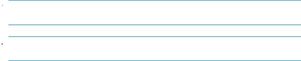
Rear panel components
15461
Item Description
1Power supply 1
2Fan module 1
37-segment display board
4SAS in connector 
5
SAS out connector
6I/O module
7Future use
8Fan module 2
9Power supply 2
12 Identifying the components
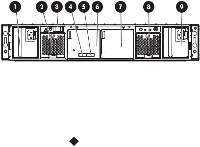
Rear panel LEDs and buttons
Item Description
1I/O module LED
2UID button/LED
3Heartbeat LED
4Fan module LED
5System fault LED
6Power On/Standby button/system power LED
7Power supply LED
15462
Status
Green = System activity Amber = Fault
Off = No system activity
Blue = Identified
Blue flashing = Active remote management Off = No active remote management
Green = System activity Amber = Fault
Off = No system activity
Green = Normal operation Amber = Fault condition
Off = Fan unseated form connector or failed
Amber = Fault condition Off = No fault condition
Green = On
Amber = Standby (power present) Off = Off
Green = Power turned on and power supply functioning properly Amber = Standby (auxiliary power present)
Blinking amber = Power to this power supply not present Off = One or more of the following conditions exists:
•A/C power unavailable
•Power supply failed
•Power supply exceeded current limit
user guide |
13 |
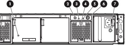
Hard drive bay numbers
1 |
6 |
11 |
16 |
21 |
2 |
7 |
12 |
17 |
22 |
3 |
8 |
13 |
18 |
23 |
4 |
9 |
14 |
19 |
24 |
5 |
10 |
15 |
20 |
25 |
|
|
|
|
15463 |
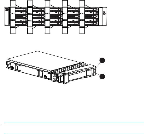
Hard drive LEDs
1 |
2 |
15464
Item Description
1Fault/UID LED (amber/blue)
2Online/activity LED (green)
Hard drive LED combinations
 NOTE:
NOTE:
Predictive failure alerts can occur only when the enclosure is connected to a Smart Array controller.
14 Identifying the components
Table 2 LED Failure/Fault Alerts
Online/activity LED (green) |
Fault/UID LED (amber/blue) |
Interpretation |
|
|
|
On, off, or flashing |
Alternating amber and blue |
The drive has failed, or a predictive |
|
|
failure alert has been received for |
|
|
this drive; it also has been selected |
|
|
by a management application. |
|
|
|
On, off, or flashing |
Steadily blue |
The drive is operating normally, |
|
|
and it has been selected by a |
|
|
management application. |
|
|
|
On |
Amber, flashing regularly (1 Hz) |
A predictive failure alert has been |
|
|
received for this drive. Replace the |
|
|
drive as soon as possible. |
On |
Off |
The drive is online, but it is not |
|
|
currently active. |
|
|
|
Flashing regularly (1 Hz) |
Amber, flashing regularly (1 Hz) |
Do not remove the drive. Removing |
|
|
a drive may terminate the current |
|
|
operation and cause data loss. |
|
|
The drive is part of an array that |
|
|
is undergoing capacity expansion |
|
|
or a stripe size migration, but a |
|
|
predictive failure alert has been |
|
|
received for this drive. To minimize |
|
|
the risk of data loss, do not replace |
|
|
the drive until the expansion or |
|
|
migration is complete. |
|
|
|
Flashing regularly (1 Hz) |
Off |
Do not remove the drive. |
|
|
Removing a drive may terminate |
|
|
the current operation and cause |
|
|
data loss. The drive is rebuilding, |
|
|
or it is part of an array that is |
|
|
undergoing capacity expansion or |
|
|
a stripe size migration. |
|
|
|
Flashing irregularly |
Amber, flashing regularly (1 Hz) |
The drive is active, but a predictive |
|
|
failure alert has been received for |
|
|
this drive. Replace the drive as |
|
|
soon as possible. |
|
|
|
Flashing irregularly |
Off |
The drive is active, and it is |
|
|
operating normally. |
|
|
|
Off |
Steadily amber |
A critical fault condition has been |
|
|
identified for this drive, and the |
|
|
controller has placed it offline. |
|
|
Replace the drive as soon as |
|
|
possible. |
|
|
|
Off |
Amber, flashing regularly (1 Hz) |
A predictive failure alert has been |
|
|
received for this drive. Replace the |
|
|
drive as soon as possible. |
|
|
|
Off |
Off |
The drive is offline, a spare, or not |
|
|
configured as part of an array. |
7-segment display board
The 7-segment display board allows you to identify the following:
•The port on the host controller to which the MSA70 is connected. There are two external ports on the host controller; each port allows you to connect up to two MSA70s to the controller. Because
user guide |
15 |
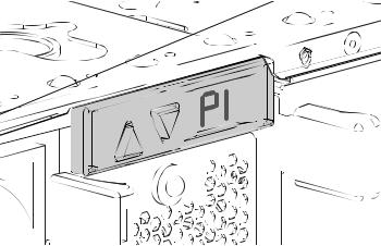
one additional MSA70 can be attached to each of the MSA70s, a total of four MSA70s can be connected to the host controller. See Cascading (1+1) configuration.
•The box ID number assigned to the MSA70 based on how it is connected to the host controller. If there are multiple MSA70s attached to the controller, the box ID number identifies the order in which they are attached.
When the MSA70 is connected to the host controller, the controller automatically assigns the port and box ID numbers to the enclosure. The following table shows MSA70 enclosures and their associated port and box ID assignments:
Storage Enclosure |
Port |
Box ID |
|
|
|
MSA70 enclosure 1 |
P1 |
B1 |
|
|
|
MSA70 enclosure 2 |
P1 |
B2 |
|
|
|
MSA70 enclosure 3 |
P2 |
B3 |
|
|
|
MSA70 enclosure 4 |
P2 |
B4 |
|
|
|
To view the port to which the MSA70 is connected, press the up arrow button on the 7-segment display board. To view the box ID number, press the down button.
15487
You can also view the port and box ID numbers within Array Configuration Utility (ACU), HP Systems Insight Manager (HP SIM), and Array Diagnostic Utility (ADU).
16 Identifying the components

2 Powering up and powering down the enclosure
 IMPORTANT:
Before installing this product, read the Important Safety Information document provided.
Powering up
Observe the following guidelines before powering up the enclosure:
•Install all components of the enclosure.
•Install hard drives in the enclosure so the connected host controller can identify and configure them at powerup.
•Always power up the enclosure first, and then the server. This ensures that the servers, during their discovery, see the enclosure as an operational device. If you do not power up the enclosure before powering up the servers, you will need to power down the servers, ensure that the enclosure is powered up, and then power back up the servers.
To power up the enclosure:
1.Complete server hardware installation and cabling. See the server documentation.
2.Connect the SAS cables and power cords to the enclosure. See Choosing a configuration.
3.Press and hold the Power On/Standby button. Wait and observe the system power LED and fan modules. When the enclosure powers up, the system power LED illuminates solid green and the fans spin to a high speed, and then spin down to a low speed.
4.Power up the servers. See the server documentation.
Powering down
 CAUTION:
Be sure that the server is the first unit to be powered down and the last to be powered back up. Taking this precaution ensures that the system does not erroneously mark the drives as failed when the server is powered up.
 IMPORTANT:
If installing a hot-plug device, it is not necessary to power down the enclosure.
To power down the enclosure:
1.Power down any attached servers. See the server documentation.
2.Press the Power On/Standby button on the enclosure. Wait for the system power LED to change from green to amber.
3.Disconnect the power cords.
The system is now without power.
user guide |
17 |
 Loading...