


 Loading...
HP Scanjet Enterprise 8500 fn1 HP Digital Sender Flow 8500 fn1
Service Manual

8500 fn1
Service Manual
Copyright and license
© 2013 Copyright Hewlett-Packard
Development Company, L.P.
Reproduction, adaptation, or translation without prior written permission is prohibited, except as allowed under the copyright laws.
The information contained herein is subject to change without notice.
The only warranties for HP products and services are set forth in the express warranty statements accompanying such products and services. Nothing herein should be construed as constituting an additional warranty. HP shall not be liable for technical or editorial errors or omissions contained herein.
Part number: L2717-90014
Edition 2, 10/2013
Trademark credits
Adobe®, Acrobat®, and PostScript® are trademarks of Adobe Systems Incorporated.
ENERGY STAR® and the ENERGY STAR® mark are registered U.S. marks.
Microsoft®, Windows®, Windows® XP, and Windows Vista® are U.S. registered trademarks of Microsoft Corporation.

Table of contents
1 Theory of operation .......................................................................................................... |
1 |
Flatbed scanner and ADF assembly ............................................................................................ |
3 |
Network electronics assembly .................................................................................................... |
4 |
User interface assembly ............................................................................................................ |
6 |
2 Removal and replacement ................................................................................................ |
7 |
Introduction ............................................................................................................................. |
8 |
Removal and replacement strategy ............................................................................................. |
9 |
Electrostatic discharge ............................................................................................................ |
10 |
Required tools ........................................................................................................................ |
11 |
Types of screws ..................................................................................................................... |
12 |
Service approach ................................................................................................................... |
15 |
Before performing service ........................................................................................ |
15 |
Backup product data ................................................................................ |
15 |
After performing service ........................................................................................... |
15 |
Restore product data ................................................................................ |
16 |
Save and repair process ........................................................................... |
16 |
Post-service test ....................................................................................................... |
16 |
Quality test .............................................................................................. |
17 |
Customer self repair (CSR) assemblies ...................................................................................... |
18 |
ADF rollers ............................................................................................................. |
18 |
Remove the ADF rollers: ............................................................................ |
18 |
Separation pad ........................................................................................ |
21 |
Update the document feeder kit replacement history ..................................... |
22 |
Set the Very Low Settings option from the control panel ................................. |
22 |
Control-panel assembly ............................................................................................ |
24 |
Reinstall the control-panel assembly ............................................................ |
25 |
Hard disk drive ....................................................................................................... |
26 |
Remove the hard disk drive ....................................................................... |
26 |
Reinstall the hard disk drive ........................................................ |
29 |
Reload the firmware .................................................................. |
29 |
ENWW |
iii |
Formatter PCA ........................................................................................................ |
31 |
Reinstall the formatter PCA ........................................................................ |
36 |
Keyboard assembly ................................................................................................. |
36 |
Internal assemblies ................................................................................................................. |
39 |
Flatbed scanner and ADF assembly ........................................................................... |
39 |
Remove the flatbed scanner and ADF assembly: ........................................... |
39 |
Reinstall the flatbed scanner and ADF assembly ............................ |
42 |
Power-button assembly ............................................................................................. |
44 |
Remove the power-button assembly ............................................................ |
44 |
Reinstall the power-button assembly ............................................................ |
45 |
Interconnect cable, scanner cable, and control-panel cable .......................................... |
46 |
Remove the scanner cable, control-panel cable, and interconnect cable .......... |
46 |
Interconnect PCA, fan assembly, and DC controller PCA .............................................. |
53 |
Remove the interconnect PCA, fan assembly, and DC controller PCA: ............. |
53 |
3 Solve problems ............................................................................................................... |
59 |
Solve problems checklist ......................................................................................................... |
60 |
Administration Menu Map ....................................................................................................... |
61 |
Preboot menu options ............................................................................................................. |
62 |
Current settings page .............................................................................................................. |
63 |
Troubleshooting process .......................................................................................................... |
64 |
Determine the problem source ................................................................................... |
64 |
Troubleshooting flowchart ......................................................................... |
65 |
Power subsystem ..................................................................................................... |
68 |
Power-on checks ...................................................................................... |
68 |
Power-on troubleshooting overview .............................................. |
68 |
Firmware startup steps ............................................................... |
69 |
Control-panel checks ............................................................................................... |
73 |
Control-panel checks from the control panel ................................................. |
73 |
Control-panel checks from diagnostic mode ................................................. |
73 |
Generate debug data .............................................................................................. |
75 |
Check the maintenance history ................................................................................. |
75 |
Check the number of scans ....................................................................................... |
75 |
Tools for troubleshooting ......................................................................................................... |
76 |
Component diagnostics ............................................................................................ |
76 |
LED diagnostics ........................................................................................ |
76 |
LED indicators on the formatter .................................................... |
76 |
Interpret control-panel status lights ............................................... |
77 |
Engine diagnostics ................................................................................... |
77 |
Verify power to the flatbed scanner and ADF assembly .................. |
77 |
Test simplex scanning ................................................................ |
78 |
iv |
ENWW |
Test duplex scanning ................................................................. |
78 |
Sensor test ............................................................................................... |
78 |
Paper present sensor .................................................................. |
78 |
ADF hatch sensor ...................................................................... |
79 |
Flatbed cover sensor .................................................................. |
79 |
Multi-Pick sensor ........................................................................ |
79 |
Internal test pages ................................................................................................... |
80 |
Configuration pages ................................................................................. |
80 |
Configuration page ................................................................... |
80 |
HP embedded Jetdirect page ...................................................... |
82 |
Finding important information on the configuration pages .............. |
83 |
Usage page ............................................................................................ |
84 |
File Directory page ................................................................................... |
85 |
Web Services Status Page ......................................................................... |
86 |
Use HP Embedded Web Server features .................................................................... |
86 |
Information tab ........................................................................................ |
87 |
Control panel menus ................................................................................................ |
87 |
Administration menu ................................................................................. |
88 |
Reports menu ............................................................................ |
88 |
General Settings menu ............................................................... |
89 |
Scan/Digital Send Settings menu ................................................ |
90 |
Fax Settings menu ..................................................................... |
93 |
Display Settings menu ................................................................ |
94 |
Manage Supplies menu ............................................................. |
95 |
Network Settings menu .............................................................. |
96 |
Troubleshooting menu ................................................................ |
98 |
Device Maintenance menu ........................................................................ |
99 |
Backup/Restore menu ................................................................ |
99 |
Calibrate/Cleaning menu ........................................................ |
100 |
USB Firmware Upgrade menu ................................................... |
100 |
Service menu .......................................................................... |
100 |
Interpret control-panel messages ............................................................................. |
101 |
Control-panel message types ................................................................... |
101 |
Control-panel messages .......................................................................... |
101 |
20.00.00 Insufficient memory: <Device> To continue, touch “OK” 101 |
|
30.01.10 Scanner Failure ........................................................ |
102 |
30.01.23 Scanner Calibration Failure ....................................... |
102 |
30.01.36 Upgrade Error Try downloading upgrade again .......... |
102 |
30.01.40 Scanner Communication Failure ................................. |
102 |
30.01.47 Document Feeder Not Detected .................................. |
103 |
30.01.YY Scanner Failure ........................................................ |
103 |
ENWW |
v |
31.01.02 Jam in document feeder ............................................ |
103 |
31.01.03 Document feeder pick error ....................................... |
104 |
40.00.01 USB I/O buffer overflow To continue, touch “OK” ........ |
104 |
40.00.02 Embedded I/O buffer overflow To continue, touch |
|
“OK” ..................................................................................... |
104 |
40.00.03 EIO <X> buffer overflow To continue, touch “OK” ........ |
105 |
40.00.04 EIO <X> bad transmission To continue, touch “OK” ..... |
105 |
40.00.05 Embedded I/O bad transmission To continue, touch |
|
“OK” ..................................................................................... |
105 |
49.XX.YY Error To continue turn off then on ................................ |
105 |
57.10.01 The fan has failed Turn off and contact the administrator |
106 |
62.00.00 No system To continue turn off then on ........................ |
106 |
80.0X.YY Embedded JetDirect Error To continue turn off then on ... |
106 |
98.00.0X Corrupt data in X volume ........................................... |
107 |
Cleaning disk <X>% complete Do not power off ......................... |
107 |
Digital send communication error .............................................. |
107 |
Digital send communication error .............................................. |
107 |
Disk full Delete stored jobs ........................................................ |
108 |
Document feeder bin full .......................................................... |
108 |
Document feeder is empty ........................................................ |
108 |
Document feeder top cover open ............................................... |
108 |
Event log is empty ................................................................... |
108 |
Flatbed cover open .................................................................. |
109 |
Initializing... ........................................................................... |
109 |
Internal disk not found ............................................................. |
109 |
Internal disk not functional ........................................................ |
109 |
Internal disk not initialized ........................................................ |
109 |
Moving solenoid To exit press ................................................... |
110 |
Moving solenoid and motor To exit press ................................... |
110 |
Performing Paper Path Test… .................................................... |
110 |
Replace Document Feeder Kit ................................................... |
110 |
Unable to cancel firmware update job ....................................... |
110 |
Unable to Install ...................................................................... |
111 |
Unable to install the firmware ................................................... |
111 |
Unsupported USB accessory detected Remove USB accessory ....... |
111 |
Upgrade complete To continue turn off then on ........................... |
112 |
USB accessory needs too much power Remove USB Accessory |
|
and Turn Off then On .............................................................. |
112 |
USB needs too much power ...................................................... |
112 |
USB storage accessory removed Clearing any associated data ..... |
112 |
Event log messages ............................................................................................... |
112 |
vi |
ENWW |
Show an event log ................................................................................. |
113 |
Clear the event log ................................................................................. |
113 |
Event log message table .......................................................................... |
113 |
Clear jams .......................................................................................................................... |
136 |
Clear jams from the paper path .............................................................................. |
136 |
Solve paper-handling problems .............................................................................................. |
138 |
Paper jamming, skewing, misfeeds, or multiple-page feeds ......................................... |
138 |
Paper does not feed from the product ...................................................................... |
138 |
Originals are curling up in the document output tray .................................................. |
139 |
The bottom of the scanned image is cut off ............................................................... |
139 |
The scanned images have streaks or scratches .......................................................... |
139 |
An item loaded in the document input tray jams repeatedly ........................................ |
139 |
The product has stopped working correctly ............................................................... |
140 |
Clean the product ................................................................................................................ |
141 |
Clean the touchscreen ........................................................................................... |
141 |
Clean the scanning glass, scanning strip, and automatic document feeder (ADF) duplex |
|
background .......................................................................................................... |
141 |
Clean the rollers .................................................................................................... |
144 |
Set the Very Low Settings option from the control panel ............................... |
145 |
Solve connectivity problems ................................................................................................... |
146 |
Check the Ethernet connection ................................................................................ |
147 |
Service mode functions ......................................................................................................... |
148 |
Service menu ........................................................................................................ |
148 |
Product resets ....................................................................................................... |
151 |
Restore factory settings ............................................................................ |
151 |
Clean Disk and Partial Clean functions ..................................................... |
151 |
Active and repository firmware locations .................................... |
151 |
Partial Clean ........................................................................... |
152 |
Clean Disk ............................................................................. |
153 |
Preboot menu options ........................................................................................................... |
155 |
Solve fax problems ............................................................................................................... |
162 |
Internet Fax setup .................................................................................................. |
162 |
LAN Fax setup ...................................................................................................... |
162 |
Solve e-mail problems ........................................................................................................... |
164 |
Validate the SMTP gateway address ........................................................................ |
164 |
Validate the LDAP gateway address ........................................................................ |
164 |
Product updates ................................................................................................................... |
165 |
Determine the installed revision of firmware .............................................................. |
165 |
Perform a firmware upgrade ................................................................................... |
165 |
HP Embedded Web Server ...................................................................... |
165 |
USB storage device (Preboot menu) .......................................................... |
166 |
ENWW |
vii |
USB storage device (control-panel menu) ................................................... |
167 |
4 Parts ............................................................................................................................ |
169 |
Order parts by authorized service providers ............................................................................ |
170 |
Order parts, accessories, and supplies .................................................................... |
170 |
Customer-self repair parts ....................................................................................... |
170 |
Internal assemblies ................................................................................................ |
171 |
Appendix A Service and support ..................................................................................... |
173 |
Hewlett-Packard limited warranty statement ............................................................................. |
174 |
End User License Agreement .................................................................................................. |
176 |
Customer self-repair warranty service ..................................................................................... |
179 |
Customer support ................................................................................................................. |
180 |
Appendix B Product specifications ................................................................................... |
181 |
Physical specifications .......................................................................................................... |
182 |
Document feeder specifications .............................................................................................. |
182 |
Power consumption .............................................................................................................. |
182 |
Environmental specifications .................................................................................................. |
183 |
Regulatory model number ..................................................................................................... |
183 |
Appendix C Regulatory information ................................................................................. |
185 |
Environmental product stewardship program ........................................................................... |
186 |
Protecting the environment ...................................................................................... |
186 |
Plastics ................................................................................................................. |
186 |
Power consumption ............................................................................................... |
186 |
Material restrictions ............................................................................................... |
186 |
Disposal of waste equipment by users in private households in the European Union ...... |
187 |
Chemical substances ............................................................................................. |
187 |
For more information ............................................................................................. |
187 |
Certificate of Volatility .......................................................................................................... |
188 |
Volatile memory .................................................................................................... |
188 |
Non-volatile memory ............................................................................................. |
188 |
Hard disk drive memory ......................................................................................... |
188 |
Index ............................................................................................................................... |
189 |
viii |
ENWW |
1 Theory of operation


 NOTE: The name for this product was changed to include the word “Flow”. There is no functional difference between the HP Scanjet Enterprise 8500 fn1 (L2717A) and the HP Digital Sender Flow 8500 fn1 (L2719A). Service parts containing the product name have been updated to include the words “Digital Sender” and “Flow”.
The 8500 fn1 is a fleet-compliant network scanner with an integrated legal-size flatbed scanner and single-pass duplex automatic document feeder (ADF). The input tray for the ADF holds 100 pages of standard size paper and can scan at 60 pages per minute (ppm) for simplex scanning and 120 ppm for duplex scanning.
The product has three hardware subassemblies:
●Flatbed scanner and ADF assembly
●Network electronics assembly
●User interface (control panel) assembly
ENWW |
1 |

Figure 1-1 Hardware subassemblies
2 |
Chapter 1 Theory of operation |
ENWW |
Flatbed scanner and ADF assembly
The scanner can scan paper up to 216 mm (8.5 in) x 863.6 mm (34 in) in size. Paper must be placed in the ADF input tray or on the flatbed glass before the scanning can be initiated. Output from the scanner is in .JPEG format and is transferred to a network using a Hi-Speed USB interface.
The major hardware components associated with this assembly are:
●ADF with an integrated scan module
●Flatbed scanner assembly
●Scanner control-board assembly
ENWW |
Flatbed scanner and ADF assembly |
3 |

Network electronics assembly
The network electronics assembly controls all functions within the product and provides a connection to the external gigabit network interface for the product. This assembly only accepts files from a USB interface in .JPEG format from the flatbed scanner and ADF assembly. The assembly stores the files on the encrypted hard disk drive for additional post-scan processing and routing based on the options selected by the user.
Figure 1-2 Network electronics assembly overview
4 |
Chapter 1 Theory of operation |
ENWW |

Table 1-1 Network electronic assembly components
Subassembly |
Subassembly |
Subassembly |
Subassembly |
|
|
|
|
Network electronics (formatter |
|
|
|
board) |
|
|
|
|
|
|
|
Interconnect circuit board |
|
|
|
(ICB) |
|
|
|
|
|
|
|
Power button board |
|
|
|
|
|
|
|
Power input board |
|
|
|
|
|
|
|
Interface cables |
From ICB |
USB cable to scanner |
|
|
|
|
|
|
|
USB cable to control panel |
|
|
|
(non-standard voltages) |
|
|
|
|
|
|
|
ICB cable assembly |
DC power cable to scanner |
|
|
|
|
|
|
|
Power/reset control to |
|
|
|
scanner |
|
|
|
|
|
|
|
System power button board |
|
|
|
|
The interconnect circuit board (ICB) subassembly within the network electronics assembly is the main communication interface for all system assemblies. This ICB controls the power sequencing of all assemblies and the system fan. All communication interfaces are routed through this assembly.
Figure 1-3 ICB connections
ENWW |
Network electronics assembly |
5 |

User interface assembly
The user interface assembly has a 203.2 mm (8 in) color LCD display with and integrated touchscreen and a full physical keyboard. The user interface assembly also includes:
●A USB-host interface connection with an integrated cover for sending output files to a USB storage accessory
●A fleet-compliant hardware integration pocket (HIP)
●Status LEDs
●Physical buttons
The user interface assembly communicates with the network electronics assembly using a USB interface through the ICB assembly.
Table 1-2 User interface assembly components
Subassembly |
Subassembly |
|
|
Control-panel assembly |
|
|
|
Physical keyboard |
Keyboard interface board |
|
|
Cables |
24-pin FFC from control panel to keyboard interface board |
|
|
6 |
Chapter 1 Theory of operation |
ENWW |

2 Removal and replacement
●Introduction
●Removal and replacement strategy
●Electrostatic discharge
●Required tools
●Types of screws
●Service approach
●Customer self repair (CSR) assemblies
●Internal assemblies


 NOTE: Your product might not appear exactly as the one shown in the photos in this chapter. Although details such as the color of the external panels and covers might be different than your product, the procedures in this chapter are appropriate for your product.
ENWW |
7 |
Introduction
This chapter describes the removal and replacement of field-replaceable units (FRUs) only.
Replacing FRUs is generally the reverse of removal. Occasionally, notes and tips are included to provide directions for difficult or critical replacement procedures.
HP does not support repairing individual subassemblies or troubleshooting to the component level.
Note the length, diameter, color, type, and location of each screw. Be sure to return each screw to its original location during reassembly.
Incorrectly routed or loose wire harnesses can interfere with other internal components and can become damaged or broken. Frayed or pinched harness wires can be difficult to find. When replacing wire harnesses, always use the provided wire loops, lance points, or wire-harness guides and retainers.
8 |
Chapter 2 Removal and replacement |
ENWW |

Removal and replacement strategy
WARNING! Turn the product off, wait 5 seconds, and then remove the power cord before attempting to remove an assembly. If this warning is not followed, severe injury can result, in addition to damage to the product. The power must be on for certain functional checks during troubleshooting. However, disconnect the power supply during parts removal.
Never operate or service the product with the protective cover removed from the laser/scanner assembly. The reflected beam, although invisible, can damage your eyes.
The sheet-metal parts can have sharp edges. Be careful when handling sheet-metal parts.
CAUTION: Do not bend or fold the flat flexible cables (FFCs) during removal or installation. Also, do not straighten pre-folds in the FFCs. You must fully seat all FFCs in their connectors. Failure to fully seat an FFC into a connector can cause a short circuit in a PCA.


 NOTE: To install a self-tapping screw, first turn it counterclockwise to align it with the existing thread pattern, and then carefully turn it clockwise to tighten. Do not overtighten. If a self-tapping screw-hole becomes stripped, repair the screw-hole or replace the affected assembly.


 TIP: For clarity, some photos in this chapter show components removed that would not be removed to

 service the product. If necessary, remove the components listed at the beginning of a procedure before proceeding to service the product.
ENWW |
Removal and replacement strategy |
9 |

Electrostatic discharge
|
CAUTION: |
|
Some parts are sensitive to electrostatic discharge (ESD). Look for the ESD reminder |
|
|||
|
|||
|
|
|
|
when removing product parts. Always perform service work at an ESD-protected workstation or mat, or use an ESD strap. If an ESD workstation, mat, or strap is not available, ground yourself by touching the sheet-metal chassis before touching an ESD-sensitive part.
Protect the ESD-sensitive parts by placing them in ESD pouches when they are out of the product.
10 Chapter 2 Removal and replacement |
ENWW |
Required tools
●Torx screwdrivers, size 10, 15, and 20
●Small flat blade screwdriver
●Needle-nose pliers
●ESD mat or ESD strap (if one is available)
●Penlight (optional)
●USB thumbdrive
ENWW |
Required tools 11 |

Types of screws
This table describes the screws that are used in the product and provides guidelines to help determine where each type of screw is used. The screws can vary in length depending on the thickness of the material that is being fastened.
Always note where each type of screw is located and replace each one in its original location.
WARNING! Make sure that components are replaced with the correct screw type. Using the incorrect screw (for example, substituting a long screw for the correct shorter screw) can cause damage to the product or interfere with product operation. Do not intermix screws that are removed with one component with the screws that are removed from another component.


 TIP: When you are disassembling the product, place the screws into the chassis holes from which

 they were removed. This prevents their loss, and ensures that the proper type and length of screw for each location is used when the product is reassembled.
Table 2-1 Common fasteners used in this product
Screw type
Silver Torx head 4 x 10 mm screw with cone washer
This screw type is shown in the following figure:
●Figure 2-31 Remove the flatbed scanner and ADF assembly (1 of 7) on page 39
12 Chapter 2 Removal and replacement |
ENWW |

Table 2-1 Common fasteners used in this product (continued)
Screw type
Silver Torx head 3 x 8 mm screw with spring washer
This screw type is shown in the following figures:
●Figure 2-61 Remove the interconnect PCA on page 56
●Figure 2-65 Remove the DC controller PCA on page 58 Torx head 4 x 34 mm screw
This screw type is shown in the following figure:
● Figure 2-63 Remove the fan assembly (2 of 3) on page 57
Torx head 3 x 10 mm screw
This screw type is shown in the following figures:
●Figure 2-32 Remove the flatbed scanner and ADF assembly (2 of 7) on page 40
●Figure 2-38 Remove the power-button assembly (1 of 3) on page 44
ENWW |
Types of screws 13 |
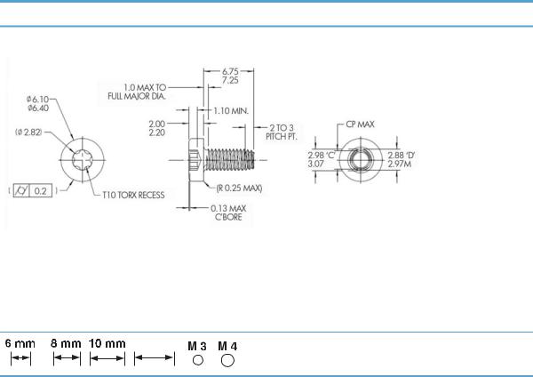
Table 2-1 Common fasteners used in this product (continued)
Screw type
Torx head 3 x 7.25 mm screw
This screw type is shown in the following figures:
●Figure 2-35 Remove the flatbed scanner and ADF assembly (5 of 7) on page 41
●Figure 2-41 Remove the scanner cable, control-panel cable, and interconnect cable (1 of 4) on page 46
●Figure 2-58 Remove the interconnect PCA, fan assembly, and DC connector PCA (4 of 6) on page 55
12 mm
Screw measurement guide
14 Chapter 2 Removal and replacement |
ENWW |

Service approach
Before performing service
●Turn off the power using the power switch.
●Unplug the power cable and network cable.
●Place the product on an ESD workstation or mat, or use an ESD strap (if one is available). If an ESD workstation, mat, or strap is not available, ground yourself by touching the sheet-metal chassis before touching an ESD-sensitive part.
 NOTE: Some procedures require that you backup product data prior to replacing the assembly.
Backup product data
To ensure that customer-specific configuration information and data are preserved, back up the product data to a portable USB storage device prior to removing these assemblies. Restore the data after replacing the assembly.


 NOTE: You can also backup product data using the HP Embedded Web Server (EWS). The EWS backs up product data to a customer specified network folder instead of the products hard drive. See the product user guide for information.
1.From the Home screen on the product control panel, touch the Device Maintenance button.
2.Open the following menus:
●Backup/Restore
●Backup Data
●Backup Now


 NOTE: Backups are stored on the hard disk drive, including regularly scheduled backups. You can export backups to a USB storage device from the hard disk drive.
3.Insert the portable USB storage device.
4.Touch Export Last Backup
5.Enter the password and confirm the password. Touch OK.
After performing service
●Connect the network cable, and then plug in the power cable.
 NOTE: Some procedures require that you perform a restore step after to replacing the assembly.
ENWW |
Service approach 15 |

Restore product data
To ensure that customer-specific configuration information and data are preserved, back up the product data to a portable USB storage device prior to removing these assemblies. Restore the data after replacing the assembly.


 NOTE: You can also restore product data using the Embedded Web Server (EWS). See the product user guide for information.
1.From the Home screen on the product control panel, touch the Device Maintenance button.
2.Open the following menus:
●Backup/Restore
●Restore Data
3.Insert the portable USB storage device.
4.Select the backup file, and then touch Restore.
5.Touch Restore.
Save and repair process
The save and repair process occurs automatically whenever the formatter PCA, interconnect PCA, or encrypted hard disk drive (HDD) are replaced. This process is transparent to the user.
CAUTION: Replacing the formatter PCA and interconnect PCA at the same time or swapping these assemblies between products can render the product unusable.
●Formatter PCA: When a replacement formatter PCA is installed and the product is turned on, NVRAM values from the interconnect PCA are transferred automatically to the replacement formatter PCA. This process allows the product to return to normal operation with all of the necessary product history.
●Interconnect PCA: When a replacement interconnect PCA is installed, NVRAM values from the formatter PCA are transferred automatically to the replacement interconnect PCA. This process allows the product to return to normal operation with all of the necessary product history.
●Hard disk drive (HDD): When a replacement hard disk drive is installed and product is turned on, the replacement hard disk drive is locked to the formatter PCA of the product. The encryption key is placed in the NVRAM of the formatter PCA and copied to the NVRAM of the interconnect PCA. This allows the backed up NVRAM values from the interconnect PCA to be restored to a replacement formatter PCA when either the formatter PCA or interconnect PCA are replaced. This process also allows the hard disk drive to function when it is transferred from a defective formatter PCA to a replacement formatter PCA. The hard disk drive cannot be used in another product or accessed from outside the product.
Post-service test
Perform the following test to verify that the repair or replacement was successful.
16 Chapter 2 Removal and replacement |
ENWW |
Quality test
1.Verify that you have completed the necessary reassembly steps.
2.Verify that the power cord and network cable are correctly connected, and then turn on the product.
3.Verify that the control panel shows the product in Ready mode.
4.Perform the scanning features of the product to ensure the product is functioning correctly. See the product user guide for information.
5.If necessary, restore any customer-specified settings.
6.Clean the outside of the product with a damp cloth.
ENWW |
Service approach 17 |

Customer self repair (CSR) assemblies
ADF rollers


 NOTE: Always replace the separation pad when replacing the ADF rollers. The ADF rollers and separation pad are included in the ADF roller replacement kit.
The ADF roller replacement kit is a consumable and is not covered under warranty or standard service agreements.
 NOTE: HP recommends that you replace the rollers every 100,000 scans.
Remove the ADF rollers:
 CAUTION: Do not touch the rollers. Oils from your fingers can impact performance.


 NOTE: If the product is on and you open and close the ADF hatch, the attention message If document feeder roller cleanup is complete, clear message displays. Touch Cancel to clear the message.
1.Open the automatic document feeder (ADF) hatch.
Figure 2-1 Remove the ADF rollers (1 of 1)
18 Chapter 2 Removal and replacement |
ENWW |
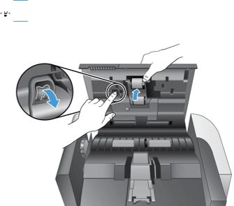
2.Slide your fingertip behind the tab on the roller assembly door, and then pull gently forward and down to open the door.

 TIP: Lift the ADF input tray slightly to make it easier to reach the tab.
Figure 2-2 Remove the ADF rollers (1 of 2)
ENWW |
Customer self repair (CSR) assemblies 19 |
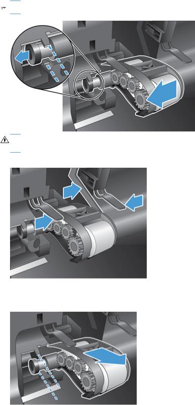
3.Holding the roller assembly door down and out of the way, grasp the roller assembly and slide it to the left to release it from the enclosure.
 NOTE: You might feel a slight resistance when sliding the roller assembly.
CAUTION: Take care not to press down on the alignment tabs or against the tab to the right of the roller assembly.
Figure 2-3 Remove the ADF rollers (1 of 3)
4.Remove the roller assembly.
Figure 2-4 Remove the ADF rollers (1 of 4)
20 Chapter 2 Removal and replacement |
ENWW |
Loading...