


 Loading...
HP Spectre x360 Convertible PC
Maintenance and Service Guide IMPORTANT! This document is intended for HP authorized service providers only.
© Copyright 2016, 2017 HP Development
Company, L.P.
Bluetooth is a trademark owned by its proprietor and used by HP Inc. under license. Intel and Core are trademarks of Intel Corporation in the U.S. and other countries. Windows is either a registered trademark or trademark of Microsoft Corporation in the United States and/or other countries. SD Logo is a trademark of its proprietor.
The information contained herein is subject to change without notice. The only warranties for HP products and services are set forth
in the express warranty statements accompanying such products and services. Nothing herein should be construed as constituting an additional warranty. HP shall not be liable for technical or editorial errors or omissions contained herein.
Second Edition: August 2017
First Edition: December 2016
Document Part Number: 912979-002
Product notice
This user guide describes features that are common to most models. Some features may not be available on your computer.
In accordance with Microsoft’s support policy, HP does not support the Windows® 8 or Windows 7 operating system on products con gured with Intel and AMD 7th generation and forward processors or provide any Windows 8 or Windows 7 drivers on http://www.support.hp.com.
Not all features are available in all editions of Windows. This computer may require upgraded and/or separately purchased hardware, drivers and/or software to take full advantage of Windows functionality. Go to http://www.microsoft.com for details.
Software terms
By installing, copying, downloading, or otherwise using any software product preinstalled on this computer, you agree to be bound by the terms of the HP End User License Agreement (EULA). If you do not accept these license terms, your sole remedy is to return the entire unused product (hardware and software) within 14 days for a full refund subject to the refund policy of your seller.
For any further information or to request a full refund of the price of the computer, please contact your seller.

Safety warning notice
 WARNING! To reduce the possibility of heat-related injuries or of overheating the device, do not place the device directly on your lap or obstruct the device air vents. Use the device only on a hard, flat
surface. Do not allow another hard surface, such as an adjoining optional printer, or a soft surface, such as pillows or rugs or clothing, to block airflow. Also, do not allow the AC adapter to contact the skin or a soft surface, such as pillows or rugs or clothing, during operation. The device and the AC adapter comply
with the user-accessible surface temperature limits de ned by the International Standard for Safety of Information Technology Equipment (IEC 60950-1).
iii
iv Safety warning notice

Table of contents
1 Product description ....................................................................................................................................... |
1 |
2 Getting to know your computer ...................................................................................................................... |
4 |
Right side ............................................................................................................................................................... |
4 |
Left side ................................................................................................................................................................. |
5 |
Display .................................................................................................................................................................... |
7 |
Keyboard area ........................................................................................................................................................ |
8 |
TouchPad ............................................................................................................................................. |
8 |
Lights ................................................................................................................................................... |
9 |
Speakers ............................................................................................................................................ |
10 |
Special keys ....................................................................................................................................... |
11 |
Bottom ................................................................................................................................................................. |
12 |
Labels ................................................................................................................................................................... |
13 |
3 Illustrated parts catalog .............................................................................................................................. |
14 |
Computer major components .............................................................................................................................. |
14 |
Miscellaneous parts ............................................................................................................................................. |
16 |
4 Removal and replacement preliminary requirements ..................................................................................... |
17 |
Tools required ...................................................................................................................................................... |
17 |
Service considerations ......................................................................................................................................... |
17 |
Plastic parts ....................................................................................................................................... |
17 |
Cables and connectors ...................................................................................................................... |
17 |
Grounding guidelines ........................................................................................................................................... |
18 |
Electrostatic discharge damage ........................................................................................................ |
18 |
5 Removal and replacement procedures ........................................................................................................... |
21 |
Bottom cover ....................................................................................................................................................... |
22 |
Battery ................................................................................................................................................................. |
23 |
Memory modules ................................................................................................................................................. |
25 |
WLAN module ...................................................................................................................................................... |
27 |
Fans, left and right ............................................................................................................................................... |
29 |
Heat sink .............................................................................................................................................................. |
31 |
Speakers .............................................................................................................................................................. |
33 |
USB/audio/power connector board ..................................................................................................................... |
36 |
Solid-state drive .................................................................................................................................................. |
39 |
v
|
RTC battery .......................................................................................................................................................... |
40 |
|
TouchPad .............................................................................................................................................................. |
41 |
|
Volume board ....................................................................................................................................................... |
43 |
|
Card reader board ................................................................................................................................................ |
45 |
|
Display assembly ................................................................................................................................................. |
47 |
|
System board ....................................................................................................................................................... |
49 |
|
Top cover/keyboard ............................................................................................................................................. |
52 |
6 Using Setup Utility (BIOS) ............................................................................................................................. |
53 |
|
|
Starting Setup Utility (BIOS) ................................................................................................................................ |
53 |
|
Updating Setup Utility (BIOS) .............................................................................................................................. |
53 |
|
Determining the BIOS version ........................................................................................................... |
53 |
|
Downloading a BIOS update .............................................................................................................. |
54 |
7 Using HP PC Hardware Diagnostics (UEFI) ....................................................................................................... |
55 |
|
|
Downloading HP PC Hardware Diagnostics (UEFI) to a USB device .................................................................... |
55 |
8 Backing up, restoring, and recovering ........................................................................................................... |
57 |
|
|
Creating recovery media and backups ................................................................................................................ |
57 |
|
Creating HP Recovery media (select products only) ......................................................................... |
57 |
|
Using Windows tools ........................................................................................................................................... |
58 |
|
Restore and recovery ........................................................................................................................................... |
59 |
|
Recovering using HP Recovery Manager ........................................................................................... |
59 |
9 p |
t ons .............................................................................................................................................. |
62 |
10 Power cord set requirements ...................................................................................................................... |
63 |
|
|
Requirements for all countries ............................................................................................................................ |
63 |
|
Requirements for speci c countries and regions ................................................................................................ |
63 |
11 Recycling .................................................................................................................................................. |
65 |
|
Index |
............................................................................................................................................................. |
66 |
vi

1Product description
Category |
Description |
15-bl100 – |
15-bl000 – |
||
|
|
|
15-bl199, |
15-bl099, |
|
|
|
|
15t-bl100 |
15t-bl000 |
|
|
|
|
|
||
Product |
HP Spectre x360 Convertible PC |
√ |
√ |
||
Name |
|
|
|
|
|
Model numbers: 15-bl100 – 15-bl199, 15t-bl100 |
√ |
|
|||
|
|
||||
|
|
|
|
||
|
Model numbers: 15-bl000 – 15-bl099, 15t-bl000 |
|
√ |
||
|
|
|
|
||
Processor |
8th generation Intel™ Core® processor |
√ |
|
||
|
Intel Core i7-8550U 1.8-GHz, max turbo 4.0-GHz, 8 GB Intel Smart Cache, 15 W) |
|
|
||
|
|
|
|
||
|
7th generation Intel Core processor |
|
√ |
||
|
Intel Core i7-7500U 2.7-GHz, max turbo 3.5-GHz, 4 GB Intel Smart Cache, 15 W) |
|
|
||
|
|
|
|
||
Graphics |
Internal graphics |
√ |
√ |
||
|
|
|
|
||
|
Intel UHD Graphics 620 |
√ |
|
||
|
|
|
|
||
|
Intel HD Graphics 620 |
|
√ |
||
|
|
|
|
||
|
Discrete graphics |
√ |
√ |
||
|
|
|
|
||
|
NVIDIA N17S-GTR-S (GeForce MX150) with 2048 MB of dedicated video memory |
√ |
|
||
|
|
|
|
||
|
NVIDIA N16S-GTR-S (GeForce 940MX) with 2048 MB of dedicated video memory |
|
√ |
||
|
|
|
|
||
Panel |
Touch screen; multi touch enabled; 16:9 ultra-wide aspect ratio; typical |
√ |
√ |
||
|
brightness: 340 nits |
|
|
||
|
|
|
|
||
|
39.6 cm (15.6-in), UWVA (3840×2160), BrightView, ultra high-de nition (UHD), white- |
√ |
√ |
||
|
light emitting (WLED), eDP, uslim-flat 2.6-mm, narrow bezel |
|
|
||
|
|
|
|
||
|
Flush glass panel cover support |
√ |
√ |
||
|
|
|
|
||
|
Supports active stylus |
√ |
√ |
||
|
|
|
|
||
|
Windows lnk certi cation |
√ |
√ |
||
|
|
|
|
||
Memory |
Two SODIMM slots - not customer accessible/upgradeable |
√ |
√ |
||
|
|
|
|
||
|
Support for DDR4-2400 dual channel |
√ |
|
||
|
|
|
|
||
|
Support for DDR4-2133 dual channel (DDR4-2400 bridge to DDR4-2133) |
|
√ |
||
|
|
|
|
||
|
Supports up to 16 GB maximum system memory in the following con gurations |
√ |
√ |
||
|
|
|
|
|
|
|
● |
16 GB (8 GB × 2) |
√ |
√ |
|
|
|
|
|
|
|
|
● |
12 GB (8 GB + 4 GB) |
√ |
√ |
|
|
|
|
|
|
|
|
● |
8 GB (4 GB × 2) |
√ |
√ |
|
|
|
|
|
||
Primary |
PCIe, NVMe, TLC, M.2 SSD on ur t on as storage |
√ |
√ |
||
storage |
|
|
|
|
|
Support for single M.2 solid-state drive con guration as storage |
√ |
√ |
|||
|
|||||
in the following con gurations
1

Category |
Description |
|
15-bl100 – |
15-bl000 – |
||
|
|
|
|
15-bl199, |
15-bl099, |
|
|
|
|
|
15t-bl100 |
15t-bl000 |
|
|
|
|
|
|
|
|
|
● |
2 TB |
|
√ |
|
|
|
|
|
|
|
|
|
|
● |
1 TB |
|
√ |
√ |
|
|
|
|
|
|
|
|
|
● |
512 GB |
|
√ |
√ |
|
|
|
|
|
|
|
|
|
● |
360 GB |
|
√ |
√ |
|
|
|
|
|
|
|
|
|
● |
256 GB |
|
√ |
√ |
|
|
|
|
|
|||
Audio |
BANG & OLUFSEN |
√ |
√ |
|||
and video |
|
|
|
|
|
|
Dual speakers |
√ |
√ |
||||
|
||||||
|
|
|
|
|||
|
Supports HP Audio Boost |
√ |
√ |
|||
|
|
|
|
|
||
|
Cortana Certi |
cation |
√ |
√ |
||
|
|
|
|
|||
Webcam and |
HP TrueVision Full HD IR camera with activity light, (2) IR lights, USB 2.0, FHD, BSI |
√ |
√ |
|||
microphone |
sensor |
|
|
|
||
|
|
|
|
|||
|
1080p by 30 frames per second |
√ |
√ |
|||
|
|
|
|
|||
|
Supports Windows Help |
√ |
√ |
|||
|
|
|
|
|||
|
Supports Voice Recognition |
√ |
√ |
|||
|
|
|
|
|||
|
Dual array digital microphones with appropriate beam-forming, echo-cancellation, |
√ |
√ |
|||
|
noise-suppression software |
|
|
|||
|
|
|
|
|||
|
HP Noise Cancellation enabled |
√ |
√ |
|||
|
|
|
|
|||
Sensors |
Accelerometer |
√ |
√ |
|||
|
|
|
|
|
||
|
Gyroscope |
|
√ |
√ |
||
|
|
|
|
|||
|
Digital Compass |
√ |
√ |
|||
|
|
|
|
|||
Wireless |
Integrated Wireless options with dual antennas (M.2): |
√ |
√ |
|||
|
|
|
|
|||
|
Two built-in WLAN antennas (in display assembly) |
√ |
√ |
|||
|
|
|
|
|
||
|
Support for |
iracast-certi ed devices (Windows 10 only) |
√ |
√ |
||
|
|
|
|
|||
|
Support for Intel WiDi (Intel 8265NV) |
√ |
√ |
|||
|
|
|
|
|||
|
WiFi SAR enabled in BIOS (Intel WLAN only) |
√ |
√ |
|||
|
|
|
|
|||
|
Support for the following WLAN modul: |
√ |
√ |
|||
|
● |
Intel Dual Band Wireless-AC 8265 802.11 ac 2×2 WiFi + Bluetooth 4.2 |
|
|
||
|
|
Combo Adapter |
|
|
||
|
|
|
|
|||
External |
HP Multi-Format Digital Media Card Reader |
√ |
√ |
|||
media cards |
|
|
|
|
|
|
Supports SD/SDHC/SDXC |
√ |
√ |
||||
|
||||||
|
|
|
|
|||
|
Push-push insertion/removal |
√ |
√ |
|||
|
|
|
|
|||
Internal card |
One M.2 Slot for WLAN |
√ |
√ |
|||
expansion |
|
|
|
|
|
|
One M.2 Slot for SSD |
√ |
√ |
||||
|
||||||
|
|
|
|
|||
Ports |
USB 3.0 Type-A port |
√ |
√ |
|||
|
|
|
|
|
|
|
2Chapter 1 Product description

Category |
Description |
15-bl100 – |
15-bl000 – |
||
|
|
|
15-bl199, |
15-bl099, |
|
|
|
|
15t-bl100 |
15t-bl000 |
|
|
|
|
|
||
|
USB 3.1 Gen 1 port |
√ |
√ |
||
|
|
|
|
||
|
USB 3.0 Type-C ports |
√ |
√ |
||
|
|
|
|
||
|
USB 3.1 Gen 2 port with Thunderbolt™ Gen 3 technology |
√ |
√ |
||
|
|
|
|
||
|
USB 3.1 Gen 1 port |
√ |
√ |
||
|
|
|
|
||
|
All ports support data transfer, power delivery, and: |
√ |
√ |
||
|
|
|
|
||
|
DisplayPort 1.2 supporting up to 3840×2160 @ 60 Hz |
√ |
√ |
||
|
|
|
|
||
|
HDMI v2.0 output support up to 3840×2160 at 60 Hz with HDCP 2.2 |
√ |
√ |
||
|
|
|
|
||
|
Headphone output and microphone input combo jack (stereo) |
√ |
√ |
||
|
|
|
|
||
|
AC adapter through Type-C port |
√ |
√ |
||
|
|
|
|
||
|
All ports support HP USB Boost |
√ |
√ |
||
|
|
|
|
||
Keyboard/ |
Full-size, Dura Coat, backlight, island-style keyboard |
√ |
√ |
||
pointing |
|
|
|
|
|
Touchpad requirements |
√ |
√ |
|||
devices |
|||||
|
|
|
|
|
|
|
● |
Multi-touch gestures enabled |
√ |
√ |
|
|
|
|
|
|
|
|
● |
Taps enabled as default |
√ |
√ |
|
|
|
|
|
|
|
|
● |
Support for Windows modern TouchPad gestures |
√ |
√ |
|
|
|
|
|
|
|
|
● |
ClickPad with image sensor |
√ |
√ |
|
|
|
|
|
||
Power |
AC adapter |
√ |
√ |
||
requirements |
|
|
|
|
|
USB Type-C, 90-W with power cords |
√ |
√ |
|||
|
|||||
|
|
|
|
||
|
Power cord |
√ |
√ |
||
|
|
|
|
||
|
1 meter power cord with tag label |
√ |
√ |
||
|
|
|
|
||
|
Battery |
√ |
√ |
||
|
|
|
|
||
|
6-cell, 79.2-WHr, 3.43-AH, Li-ion battery |
√ |
√ |
||
|
|
|
|
||
Security |
Trusted Platform Module (TPM) 2.0 support |
√ |
√ |
||
|
|
|
|
||
Operating |
Preinstalled |
√ |
√ |
||
system |
|
|
|
|
|
Windows 10 |
√ |
√ |
|||
|
|||||
|
|
|
|
||
|
Windows 10 Pro |
√ |
√ |
||
|
|
|
|
||
|
For Developed Markets (ML): |
√ |
√ |
||
|
|
|
|
||
|
Windows 10 Home Plus ML |
√ |
√ |
||
|
|
|
|
||
|
For Emerging Markets (EM): |
√ |
√ |
||
|
|
|
|
||
|
Windows 10 Home Plus EM/SL |
√ |
√ |
||
|
|
|
|
||
|
SEAP Windows 10 Home Plus |
|
√ |
||
|
|
|
|
||
Serviceability |
End user replaceable part: AC adapter |
√ |
√ |
||
|
|
|
|
|
|
3
2Getting to know your computer
Your computer features top-rated components. This chapter provides details about your components, where they're located, and how they work.
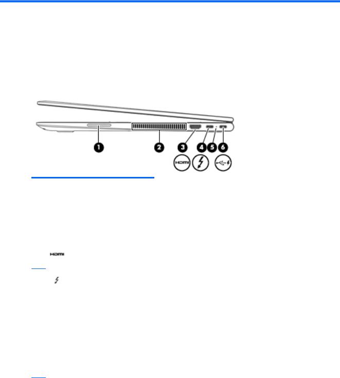
Right side
Component |
|
Description |
|
|
|
|
|
(1) |
Volume button |
Controls speaker volume on the computer. |
|
|
|
|
|
(2) |
Vent |
Enables airflow to cool internal components. |
|
|
|
NOTE: The computer fan starts up automatically to cool internal components |
|
|
|
and prevent overheating. It is normal for the internal fan to cycle on and o |
|
|
|
during routine operation. |
|
|
|
|
|
(3) |
HDMI port |
Connects an optional video or audio device, such as a high-de |
nition television, |
|
|
any compatible digital or audio component, or a high-speed |
igh-De nition |
|
|
Multimedia Interface (HDMI) device. |
|
(4)USB Type-C power connector and Thunderbolt port with HP Sleep and Charge
Connects an AC adapter that has a USB Type-C connector, supplying power to the computer and, if needed, charging the computer battery.
– and –
Connects and charges most USB devices that have a Type-C connector, such as a cell phone, camera, activity tracker, or smartwatch, and provides high-speed data transfer.
NOTE: Cables and/or adapters (purchased separately) may be required.
– and –
Connects a display device that has a USB Type-C connector, providing DisplayPort output.
NOTE: Your computer may also support a Thunderbolt docking station.
(5) |
AC adapter and battery light |
● |
White: The AC adapter is connected and the battery is fully charged. |
●Blinking white: The AC adapter is disconnected and the battery has reached a low battery level.
●Amber: The AC adapter is connected and the battery is charging.
4Chapter 2 Getting to know your computer
Component |
Description |
|
|
|
|
|
● |
The battery is not charging. |
(6)USB Type-C power connector and port with HP Sleep and Charge
Connects an AC adapter that has a USB Type-C connector, supplying power to the computer and, if needed, charging the computer battery.
– and –
When the computer is o , charges most products such as a cell phone, camera, activity tracker, or smartwatch, and provides data transfer.
NOTE: Cables and/or adapters (purchased separately) may be required.
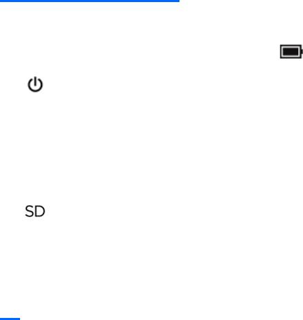
Left side
Component |
|
Description |
|
|
|
|
|
(1) |
USB 3.x SuperSpeed port with HP Sleep |
Connects a USB device, provides high-speed data transfer, and even when |
|
|
and Charge |
the computer is o , charges most products such as a cell phone, camera, |
|
|
|
activity tracker, or smartwatch. |
|
|
|
|
|
(2) |
Audio-out (headphone)/Audio-in |
Connects optional powered stereo speakers, headphones, earbuds, a |
|
|
(microphone) combo jack |
headset, or a television audio cable. Also connects an optional headset |
|
|
|
microphone. This jack does not support optional standalone microphones. |
|
|
|
WARNING! To reduce the risk of personal injury, adjust the volume before |
|
|
|
putting on headphones, earbuds, or a headset. For additional safety |
|
|
|
information, refer to the Regulatory, Safety, and Environmental Notices. |
|
|
|
To access this guide: |
|
|
|
▲ Select the Start button, select HP Help and Support, and then select |
|
|
|
|
HP Documentation. |
|
|
NOTE: When a device is connected to the jack, the computer speakers are |
|
|
|
disabled. |
|
|
|
|
|
(3) |
Power button |
● |
When the computer is o , press the button to turn on the computer. |
|
|
● |
When the computer is on, press the button briefly to initiate Sleep. |
|
|
● |
When the computer is in the Sleep state, press the button briefly to |
|
|
|
exit Sleep. |
|
|
● |
When the computer is in Hibernation, press the button briefly to exit |
|
|
|
Hibernation. |
|
|
CAUTION: Pressing and holding down the power button results in the loss |
|
|
|
of unsaved information. |
|
|
|
If the computer has stopped responding and shutdown procedures are |
|
|
|
ine |
ective, press and hold the power button down for at least 5 seconds to |
|
|
turn o the computer. |
|
Left side |
5 |
Component |
|
Description |
|
|
|
|
|
||
|
|
To learn more about your power settings, see your power options: |
||
|
|
▲ |
Right-click the Power icon |
, and then select Power Options. |
|
|
|
||
|
|
|
|
|
(4) |
Power light |
● |
On: The computer is on. |
|
|
|
● |
Blinking: The computer is in the Sleep state, a power-saving state. |
|
|
|
|
The computer shuts o power to the display and other unneeded |
|
|
|
|
components. |
|
|
|
● |
The computer is o or in Hibernation. Hibernation is a power- |
|
|
|
|
saving state that uses the least amount of power. |
|
|
|
|
||
(5) |
Vent |
Enables airflow to cool internal components. |
||
|
|
NOTE: The computer fan starts up automatically to cool internal |
||
|
|
components and prevent overheating. It is normal for the internal fan to |
||
|
|
cycle on and o during routine operation. |
||
|
|
|
||
(6) |
Memory card reader |
Reads optional memory cards that enable you to store, manage, share, or |
||
|
|
access information. |
|
|
To insert a card:
1.Hold the card label-side up, with connectors facing the computer.
2.Insert the card into the memory card reader, and then press in on the
card until it is rmly seated.
To remove a card:
▲Press in on the card, and then remove it from the memory card reader.
6Chapter 2 Getting to know your computer

Display
Component |
Description |
|
|
|
|
(1) |
WLAN antennas* (2) |
Send and receive wireless signals to communicate with wireless local area networks |
|
|
(WLANs). |
|
|
|
(2) |
Internal microphones (2) |
Record sound. |
|
|
|
(3) |
Camera light(s) |
On: One or more cameras are in use. |
|
|
|
(4) |
Camera(s) |
Allow you to video chat, record video, and record still images. Some cameras also |
|
|
allow a facial recognition logon to Windows, instead of a password logon. |
NOTE: Camera functions vary depending on the camera hardware and software installed on your product.
*The antennas are not visible from the outside of the computer, and antenna location varies. For optimal transmission, keep the areas immediately around the antennas free from obstructions.
For wireless regulatory notices, see the section of the Regulatory, Safety, and Environmental Notices that applies to your country or region.
To access this guide:
▲Select the Start button, select HP Help and Support, and then select HP Documentation.
Display 7
Keyboard area
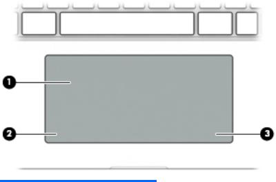
TouchPad
Component |
|
Description |
|
|
|
(1) |
TouchPad zone |
Reads your nger gestures to move the pointer or activate items on the screen. |
|
|
|
(2) |
Left TouchPad button |
Functions like the left button on an external mouse. |
|
|
|
(3) |
Right TouchPad button |
Functions like the right button on an external mouse. |
|
|
|
8Chapter 2 Getting to know your computer
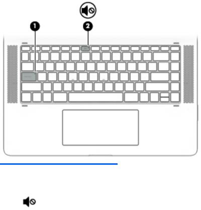
Lights
Component |
|
Description |
|
|
|
|
|
(1) |
Caps lock light |
On: Caps lock is on, which switches the key input to all capital letters. |
|
|
|
|
|
(2) |
Mute light |
● |
Amber: Computer sound is o . |
|
|
● |
Computer sound is on. |
|
|
|
|
Keyboard area |
9 |
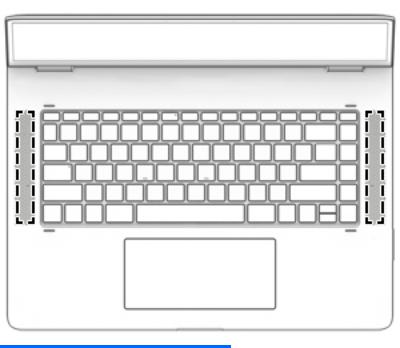
Speakers
Component |
Description |
|
|
Speakers (2) |
Produce sound. |
|
|
10 Chapter 2 Getting to know your computer
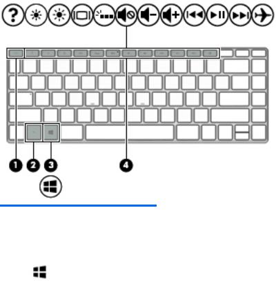
Special keys
Component |
|
Description |
|
|
|
(1) |
esc key |
Displays system information when pressed in combination with the fn key. |
|
|
|
(2) |
fn key |
Executes speci c functions when pressed in combination with another key. |
|
|
|
(3) |
Windows key |
Opens the Start menu. |
|
|
NOTE: Pressing the Windows key again will close the Start menu. |
|
|
|
(4) |
Action keys |
Execute frequently used system functions. |
|
|
NOTE: On select products, the f5 action key turns the keyboard backlight feature |
|
|
o or on. |
|
|
|
Keyboard area 11
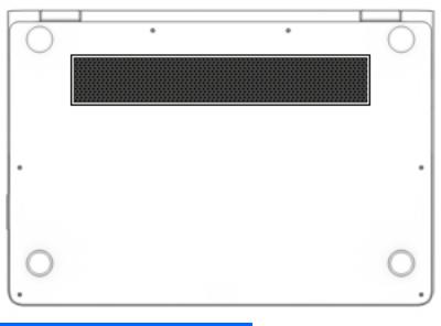
Bottom
Component |
Description |
|
|
Vent |
Enables airflow to cool internal components. |
|
NOTE: The computer fan starts up automatically to cool internal components |
|
and prevent overheating. It is normal for the internal fan to cycle on and o during |
|
routine operation. |
|
|
12 Chapter 2 Getting to know your computer

Labels
The labels affixed to the computer provide information you may need when you troubleshoot system problems or travel internationally with the computer.
 IMPORTANT: Check the following locations for the labels described in this section: the bottom of the computer, inside the battery bay, under the service door, or on the back of the display.
●Service label—Provides important information to identify your computer. When contacting support, you will probably be asked for the serial number, and possibly for the product number or the model number. Locate these numbers before you contact support.
Your service label will resemble one of the examples shown below. Refer to the illustration that most closely matches the service label on your computer.
Component
(1)Product name
(2)Serial number
(3)Product number
(4)Warranty period
(5)Model number
●Regulatory label(s)—Provide(s) regulatory information about the computer.
●Wireless certi cation label(s)—Provide(s) information about optional wireless devices and the approval markings for the countries or regions in which the devices have been approved for use.
Labels 13

3Illustrated parts catalog
 NOTE: HP continually improves and changes product parts. For complete and current information on supported parts for the computer, go to http://partsurfer.hp.com, select the country or region, and then follow the on-screen instructions.
Computer major components
14 Chapter 3 Illustrated parts catalog
Item |
Component |
Spare part |
|
|
number |
|
|
|
(1) |
Display assembly (full hinge-up) |
911082-001 |
(2)Top cover and keyboard (includes TouchPad, keyboard cable, keyboard backlight cable; top cover/keyboard spare part kits include replacement rubber feet)
|
For use in Belgium |
912995-A41 |
|
|
|
|
For use in Canada |
912995-DB1 |
|
|
|
|
For use in Denmark, Finland, and Norway |
912995-DH1 |
|
|
|
|
For use in France |
912995-051 |
|
|
|
|
For use in Germany |
912995-041 |
|
|
|
|
For use in Greece |
912995-151 |
|
|
|
|
For use in Italy |
912995-061 |
|
|
|
|
For use in the Netherlands |
912995-B31 |
|
|
|
|
For use in Russia |
912995-251 |
|
|
|
|
For use in Saudi Arabia |
912995-171 |
|
|
|
|
For use in Switzerland |
912995-BG1 |
|
|
|
|
For use in the United Kingdom and Singapore |
912995-031 |
|
|
|
|
For use in the United States |
912995-001 |
|
|
|
(3) |
TouchPad (TouchPad spare part kits include replacement rubber feet) |
913004-001 |
|
|
|
(4) |
TouchPad cable (TouchPad cable spare part kits include replacement rubber feet) |
912992-001 |
|
|
|
(5) |
Battery, 6-cell, 79-WHr, 3.43-AHr, Li-ion (battery spare part kits include rubber feet) |
902499-856 |
|
|
|
(6) |
Card reader board (card reader board spare part kits include replacement rubber feet) |
913005-001 |
|
|
|
(7) |
Card reader board cable (card reader board cable spare part kits include replacement rubber feet) |
912991-001 |
(8)Solid-state drive (solid-state drive spare part kits include replacement rubber feet)
|
2-TB, PCIe solid-state drive (for use in models with 8th generation Intel Core processors) |
941661-001 |
|
|
|
|
1-TB, PCIe solid-state drive |
913015-001 |
|
|
|
|
512-GB, PCIe solid-state drive |
913014-001 |
|
|
|
|
360-GB, PCIe solid-state drive |
920299-001 |
|
|
|
|
256-GB, PCIe solid-state drive |
913013-001 |
|
|
|
(9) |
Intel Dual Band Wireless-AC 8265 802.11 ac 2×2 WiFi + Bluetooth 4.2 Combo Adapter (WLAN module |
910264-856 |
|
spare part kits include replacement rubber feet) |
|
|
|
|
(10) |
RTC battery (RTC battery spare part kits include replacement rubber feet) |
913007-001 |
|
|
|
(11) |
USB/audio/power connector board (spare part kits include replacement rubber feet) |
913006-001 |
|
|
|
(12) |
USB/audio/power connector board cable (spare part kits include replacement rubber feet) |
912993-001 |
|
|
|
(13) |
Volume board cable (volume board cable spare part kits include replacement rubber feet) |
913633-001 |
|
|
|
(14) |
Volume board (volume board spare part kits include replacement rubber feet) |
913634-001 |
|
|
|
Computer major components 15

Item |
Component |
Spare part |
|
|
number |
(15)System board (includes processor and replacement thermal material; system board spare part kits include replacement rubber feet)
|
Intel Core i7-8550U processor, 2-GB of discrete graphics memory, and the Windows 10 operating system |
941662-601 |
|
|
|
|
Intel Core i7-8550U processor, 2-GB of discrete graphics memory, and a non-Windows operating system |
941662-001 |
|
|
|
|
Intel Core i7-7500U processor, 2-GB of discrete graphics memory, and the Windows 10 operating system |
911083-601 |
|
|
|
|
Intel Core i7-7500U processor, 2-GB of discrete graphics memory, and a non-Windows operating system |
911083-001 |
|
|
|
(16) |
Heat sink (includes replacement thermal material; heat sink spare part kits include replacement rubber |
911081-001 |
|
feet) |
|
|
|
|
(17) |
Fan, left (fan spare part kits include replacement rubber feet) |
912994-001 |
|
|
|
(18) |
Fan, right (fan spare part kits include replacement rubber feet) |
919437-001 |
(19)Memory modules (DDR4-2400; memory spare part kits include replacement rubber feet)
|
8 GB |
862398-857 |
|
|
|
|
4 GB |
862397-857 |
|
|
|
(20) |
Left Speaker Kit (speaker spare part kits include replacement rubber feet) |
913009-001 |
|
|
|
(21) |
Right Speaker Kit (speaker spare part kits include replacement rubber feet) |
913008-001 |
|
|
|
(22) |
Bottom cover (includes rubber feet) |
912990-001 |
|
|
|
Miscellaneous parts
Component |
Spare part |
|
number |
|
|
AC adapter, 90-W, 3-pin, PFC, USB-C |
904144-850 |
|
|
USB-C to RJ-45 adapter |
855560-001 |
|
|
USB-C to VGA adapter |
831751-001 |
|
|
USB-C to USB-A adapter |
833960-001 |
|
|
Power cord (C5, 3-pin, 1.0-m) |
|
|
|
For use in Denmark |
213353-011 |
|
|
For use in Europe (Austria, Belgium, Finland, France, Germany, the Netherlands, Norway and Sweden) |
213350-012 |
|
|
For use in North America |
213349-013 |
|
|
For use in Switzerland |
213354-011 |
|
|
For use in the United Kingdom and Singapore |
213351-011 |
|
|
Screw Kit |
910949-001 |
|
|
Rubber feet |
910948-001 |
|
|
Active pen |
920241-001 |
|
|
Notebook sleeve case |
913622-001 |
|
|
16 Chapter 3 Illustrated parts catalog

4Removal and replacement preliminary requirements
Tools required
You will need the following tools to complete the removal and replacement procedures:
●Flat-bladed screw driver
●Magnetic screw driver
●Phillips P0 screw driver
Service considerations
The following sections include some of the considerations that you must keep in mind during disassembly and assembly procedures.
 NOTE: As you remove each subassembly from the tablet, place the subassembly (and all accompanying screws) away from the work area to prevent damage.
Plastic parts
 CAUTION: Using excessive force during disassembly and reassembly can damage plastic parts. Use care when handling the plastic parts. Apply pressure only at the points designated
in the maintenance instructions.
Cables and connectors
 CAUTION: When servicing the tablet, be sure that cables are placed in their proper locations during the reassembly process. Improper cable placement can damage the tablet.
Cables must be handled with extreme care to avoid damage. Apply only the tension required to unseat or seat the cables during removal and insertion. Handle cables by the connector whenever possible. In all cases, avoid bending, twisting, or tearing cables. Be sure that cables are routed in such a way that they cannot be caught or snagged by parts being removed or replaced. Handle flex cables with extreme care; these cables tear easily.
Tools required 17
Loading...