


TNC 640
Table of contents
 Loading...
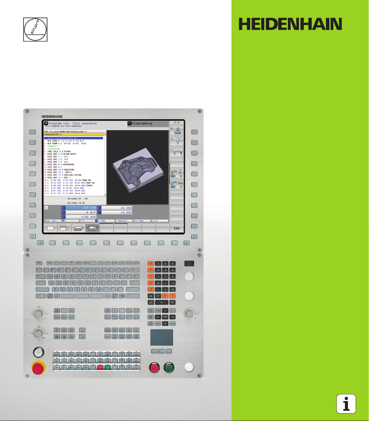
User’s Manual
ISO Programming
TNC 640
NC Software
340590-01
340591-01
340594-01
English (en)
4/2012
Controls of the TNC
1
50
0
50
100
F %
1
50
0
50
100
S %
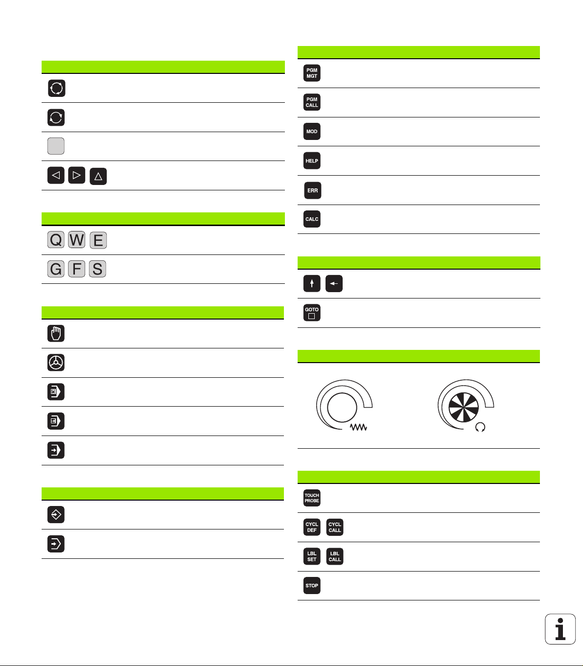
Keys on visual display unit
Key Function
Split screen layout
Toggle the display between machining
and programming modes
Soft keys for selecting functions on
screen
Switch the soft-key rows
Alphanumeric keyboard
Key Function
File names, comments
DIN/ISO programming
Machine operating modes
Key Function
Manual Operation
Electronic Handwheel
Program/file management, TNC functions
Key Function
Select or delete programs and files,
external data transfer
Define program call, select datum and
point tables
Select MOD functions
Display help text for NC error messages,
call TNCguide
Display all current error messages
Show calculator
Navigation keys
Key Function
Move highlight
Go directly to blocks, cycles and
parameter functions
Potentiometer for feed rate and spindle speed
Feed rate Spindle speed
Programming modes
Key Function
Positioning with Manual Data Input
Program Run, Single Block
Program Run, Full Sequence
Cycles, subprograms and program section repeats
Key Function
Define touch probe cycles
Programming and Editing
Define and call cycles
Test Run
Enter and call labels for subprogramming
and program section repeats
Enter program stop in a program
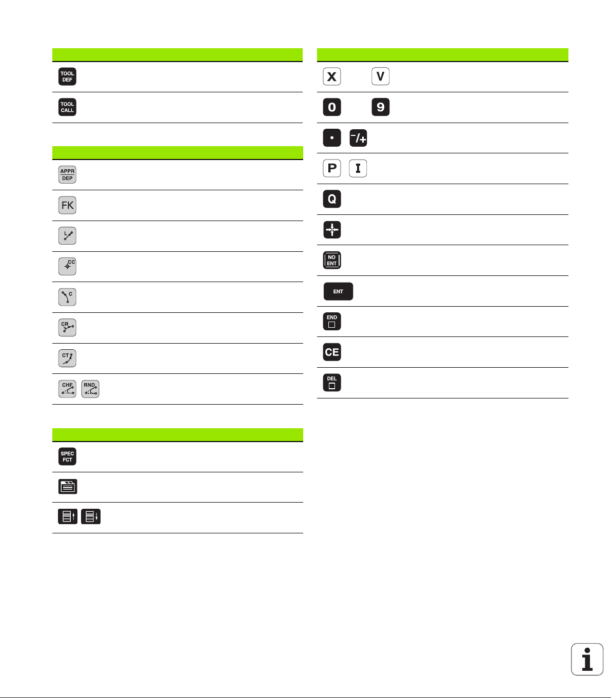
Tool functions
Key Function
Define tool data in the program
Coordinate axes and numbers: Entering and editing
Key Function
Select coordinate axes or
enter them into the program
Call tool data
Programming path movements
Key Function
Approach/depart contour
FK free contour programming
Straight line
Circle center/pole for polar coordinates
Circle with center
Circle with radius
Circular arc with tangential connection
Chamfer/Corner rounding
Numbers
Decimal point / Reverse algebraic sign
Polar coordinate input / Incremental
values
Q parameter programming /
Q parameter status
Save actual position or values from
calculator
Skip dialog questions, delete words
Confirm entry and resume dialog
Conclude block and exit entry
Clear numerical entry or TNC error
message
Abort dialog, delete program section
Special functions
Key Function
Show special functions
Select the next tab in forms
Up/down one dialog box or button

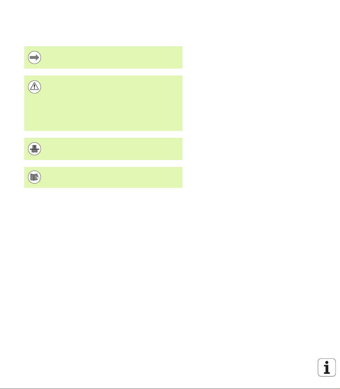
About this Manual
The symbols used in this manual are described below.
This symbol indicates that important notes about the
function described must be regarded.
This symbol indicates that there is one or more of the
following risks when using the described function:
Danger to workpiece
Danger to fixtures
Danger to tool
Danger to machine
Danger to operator
This symbol indicates that the described function must be
adapted by the machine tool builder. The function
described may therefore vary depending on the machine.
This symbol indicates that you can find detailed
information about a function in another manual.
About this Manual
Would you like any changes, or have you found any errors?
We are continuously striving to improve documentation for you.
Please help us by sending your requests to the following e-mail
address: tnc-userdoc@heidenhain.de.
HEIDENHAIN TNC 640 5

TNC Model, Software and Features
This manual describes functions and features provided by TNCs as of
the following NC software numbers.
TNC model NC software number
TNC 640 340590-01
TNC 640 E 340591-01
TNC 640 Programming Station 340594-01
The suffix E indicates the export version of the TNC. The export
version of the TNC has the following limitations:
Simultaneous linear movement in up to 4 axes
The machine tool builder adapts the usable features of the TNC to his
machine by setting machine parameters. Some of the functions
described in this manual may therefore not be among the features
provided by the TNC on your machine tool.
TNC functions that may not be available on your machine include:
Tool measurement with the TT
Please contact your machine tool builder to become familiar with the
TNC Model, Software and Features
features of your machine.
Many machine manufacturers, as well as HEIDENHAIN, offer
programming courses for the TNCs. We recommend these courses as
an effective way of improving your programming skill and sharing
information and ideas with other TNC users.
User’s Manual for Cycle Programming:
All of the cycle functions (touch probe cycles and fixed
cycles) are described in a separate manual. Please contact
HEIDENHAIN if you need a copy of this User’s Manual.
ID: 892905-xx
6

Software options
The TNC 640 features various software options that can be enabled by
your machine tool builder. Each option is to be enabled separately and
contains the following respective functions:
Software option 1 (option number #08)
Cylinder surface interpolation (Cycles 27, 28 and 29)
Feed rate in mm/min for rotary axes: M116
Tilting the machining plane (plane functions, Cycle 19 and 3D-ROT
soft key in the Manual Operation mode)
Circle in 3 axes with tilted working plane
Software option 2 (option number #09)
5-axis interpolation
3-D machining:
M128: Maintaining the position of the tool tip when positioning
with tilted axes (TCPM)
FUNCTION TCPM: Maintaining the position of the tool tip when
positioning with tilted axes (TCPM) in selectable modes
M144: Compensating the machine’s kinematic configuration for
ACTUAL/NOMINAL positions at end of block
LN blocks (3-D compensation)
TNC Model, Software and Features
HEIDENHAIN DNC (option number #18)
Communication with external PC applications over COM
component
Additional conversational language (option number #41)
Function for enabling the conversational languages Slovenian,
Slovak, Norwegian, Latvian, Estonian, Korean, Turkish, Romanian,
Lithuanian.
Display step (option number #23)
Input resolution and display step:
Linear axes down to 0.01 µm
Rotary axes to 0.00001°
Double speed (option number #49)
Double-speed control loops are used primarily for high-speed
spindles as well as for linear motors and torque motors
HEIDENHAIN TNC 640 7

KinematicsOpt software option (option number #48)
Touch-probe cycles for inspecting and optimizing the machine
accuracy
Software option Mill-Turning (option number #50)
Functions for milling/turning mode:
Switching between Milling/Turning mode of operation
Constant cutting speed
Tool-tip radius compensation
Turning cycles
Extended Tool Management software option
(option number #93)
Tool management that can be changed by the machine
manufacturer using Python scripts
TNC Model, Software and Features
8

Feature content level (upgrade functions)
Along with software options, significant further improvements of the
TNC software are managed via the Feature Content Level (FCL)
upgrade functions. Functions subject to the FCL are not available
simply by updating the software on your TNC.
All upgrade functions are available to you without
surcharge when you receive a new machine.
Upgrade functions are identified in the manual with FCL n, where n
indicates the sequential number of the feature content level.
You can purchase a code number in order to permanently enable the
FCL functions. For more information, contact your machine tool
builder or HEIDENHAIN.
Intended place of operation
The TNC complies with the limits for a Class A device in accordance with the specifications in EN 55022, and is intended for use primarily in industrially-zoned areas.
Legal information
This product uses open source software. Further information is
available on the control under
U Programming and Editing operating mode
U MOD function
U LICENSE INFO soft key
TNC Model, Software and Features
HEIDENHAIN TNC 640 9

TNC Model, Software and Features
10

Contents
First Steps with the TNC 640
1
Introduction
2
Programming: Fundamentals,
File Management
3
Programming: Programming Aids
4
Programming: Tools
5
Programming: Programming Contours
6
Programming: Subprograms and
Program Section Repeats
7
Programming: Q Parameters
8
Programming: Miscellaneous Functions
9
Programming: Special Functions
10
Programming: Multiple Axis Machining
11
Programming: Pallet Editor
12
Manual Operation and Setup
13
Positioning with Manual Data Input
14
Test Run and Program Run
15
MOD Functions
16
Tables and Overviews
17
HEIDENHAIN TNC 640 11


1 First Steps with the TNC 640 ..... 33
1.1 Overview ..... 34
1.2 Machine Switch-On ..... 35
Acknowledging the power interruption and moving to the reference points ..... 35
1.3 Programming the First Part ..... 36
Selecting the correct operating mode ..... 36
The most important TNC keys ..... 36
Creating a new program/file management ..... 37
Defining a workpiece blank ..... 38
Program layout ..... 39
Programming a simple contour ..... 40
Creating a cycle program ..... 43
1.4 Graphically Testing the First Program ..... 45
Selecting the correct operating mode ..... 45
Selecting the tool table for the test run ..... 45
Choosing the program you want to test ..... 46
Selecting the screen layout and the view ..... 46
Starting the program test ..... 46
1.5 Tool Setup ..... 47
Selecting the correct operating mode ..... 47
Preparing and measuring tools ..... 47
The tool table TOOL.T ..... 47
The pocket table TOOL_P.TCH ..... 48
1.6 Workpiece Setup ..... 49
Selecting the correct operating mode ..... 49
Clamping the workpiece ..... 49
Aligning the workpiece with a 3-D touch probe system ..... 50
Datum setting with a 3-D touch probe ..... 51
1.7 Running the First Program ..... 52
Selecting the correct operating mode ..... 52
Choosing the program you want to run ..... 52
Starting the program ..... 52
HEIDENHAIN TNC 640 13

2 Introduction ..... 53
2.1 The TNC 640 ..... 54
Programming: HEIDENHAIN conversational and ISO formats ..... 54
Compatibility ..... 54
2.2 Visual Display Unit and Keyboard ..... 55
Visual display unit ..... 55
Setting the screen layout ..... 56
Operating panel ..... 57
2.3 Operating Modes ..... 58
Manual Operation and El. Handwheel ..... 58
Positioning with Manual Data Input ..... 58
Programming and Editing ..... 59
Test Run ..... 59
Program Run, Full Sequence and Program Run, Single Block ..... 60
2.4 Status Displays ..... 61
"General" status display ..... 61
Additional status displays ..... 63
2.5 Window Manager ..... 70
Soft-key row ..... 71
2.6 Accessories: HEIDENHAIN 3-D Touch Probes and Electronic Handwheels ..... 72
3-D touch probes ..... 72
HR electronic handwheels ..... 73
14

3 Programming: Fundamentals, File Management ..... 75
3.1 Fundamentals ..... 76
Position encoders and reference marks ..... 76
Reference system ..... 76
Reference system on milling machines ..... 77
Designation of the axes on milling machines ..... 77
Polar coordinates ..... 78
Absolute and incremental workpiece positions ..... 79
Setting the datum ..... 80
3.2 Creating and Writing Programs ..... 81
Organization of an NC program in DIN/ISO ..... 81
Define the blank: G30/G31 ..... 81
Creating a new part program ..... 82
Programming tool movements in DIN/ISO format ..... 84
Actual position capture ..... 85
Editing a program ..... 86
The TNC search function ..... 90
3.3 File Management: Fundamentals ..... 92
Files ..... 92
Showing externally created files on the TNC ..... 94
Data backup ..... 94
3.4 Working with the File Manager ..... 95
Directories ..... 95
Paths ..... 95
Overview: Functions of the file manager ..... 96
Calling the file manager ..... 97
Selecting drives, directories and files ..... 98
Creating a new directory ..... 100
Creating a new file ..... 100
Copying a single file ..... 101
Copying files into another directory ..... 102
Copying a table ..... 103
Copying a directory ..... 104
Choosing one of the last files selected ..... 105
Deleting a file ..... 105
Deleting a directory ..... 106
Marking files ..... 107
Renaming a file ..... 108
File sorting ..... 108
Additional functions ..... 109
Additional tools for management of external file types ..... 110
Data transfer to or from an external data medium ..... 115
The TNC in a network ..... 117
USB devices on the TNC ..... 118
HEIDENHAIN TNC 640 15

4 Programming: Programming Aids ..... 119
4.1 Adding Comments ..... 120
Application ..... 120
Entering comments during programming ..... 120
Inserting comments after program entry ..... 120
Entering a comment in a separate block ..... 120
Functions for editing of the comment ..... 121
4.2 Display of NC Programs ..... 122
Syntax highlighting ..... 122
Scrollbar ..... 122
4.3 Structuring Programs ..... 123
Definition and applications ..... 123
Displaying the program structure window / Changing the active window ..... 123
Inserting a structuring block in the (left) program window ..... 123
Selecting blocks in the program structure window ..... 123
4.4 On-Line Calculator ..... 124
Operation ..... 124
4.5 Programming Graphics ..... 126
Generating / not generating graphics during programming ..... 126
Generating a graphic for an existing program ..... 126
Block number display ON/OFF ..... 127
Erasing the graphic ..... 127
Showing grid lines ..... 127
Magnifying or reducing a detail ..... 127
4.6 Error Messages ..... 128
Display of errors ..... 128
Open the error window ..... 128
Closing the error window ..... 128
Detailed error messages ..... 129
INTERNAL INFO soft key ..... 129
Clearing errors ..... 130
Error log ..... 130
Keystroke log ..... 131
Informational texts ..... 132
Saving service files ..... 132
Calling the TNCguide help system ..... 132
4.7 Context-Sensitive Help System ..... 133
Application ..... 133
Working with the TNCguide ..... 134
Downloading current help files ..... 138
16

5 Programming: Tools ..... 141
5.1 Entering Tool-Related Data ..... 142
Feed rate F ..... 142
Spindle speed S ..... 142
5.2 Tool Data ..... 143
Requirements for tool compensation ..... 143
Tool numbers and tool names ..... 143
Tool length L ..... 143
Tool radius R ..... 143
Delta values for lengths and radii ..... 144
Entering tool data into the program ..... 144
Entering tool data in the table ..... 145
Pocket table for tool changer ..... 152
Calling tool data ..... 155
Tool change ..... 156
Tool management (software option) ..... 161
5.3 Tool Compensation ..... 168
Introduction ..... 168
Tool length compensation ..... 168
Tool radius compensation ..... 169
HEIDENHAIN TNC 640 17

6 Programming: Programming Contours ..... 173
6.1 Tool Movements ..... 174
Path functions ..... 174
Miscellaneous functions M ..... 174
Subprograms and program section repeats ..... 174
Programming with Q parameters ..... 174
6.2 Fundamentals of Path Functions ..... 175
Programming tool movements for workpiece machining ..... 175
6.3 Contour Approach and Departure ..... 178
Starting point and end point ..... 178
Tangential approach and departure ..... 180
6.4 Path Contours—Cartesian Coordinates ..... 182
Overview of path functions ..... 182
Programming path functions ..... 182
Straight line at rapid traverse G00
Straight line with feed rate G01 F ..... 183
Inserting a chamfer between two straight lines ..... 184
Corner rounding G25 ..... 185
Circle center I, J ..... 186
Circular path C around circle center CC ..... 187
Circular path G02/G03/G05 with defined radius ..... 188
Circular path G06 with tangential connection ..... 190
6.5 Path Contours—Polar Coordinates ..... 195
Overview ..... 195
Zero point for polar coordinates: pole I, J ..... 196
Straight line at rapid traverse G10
Straight line with feed rate G11 F ..... 196
Circular path G12/G13/G15 around pole I, J ..... 197
Circular path G16 with tangential connection ..... 198
Helical interpolation ..... 199
18

7 Programming: Subprograms and Program Section Repeats ..... 203
7.1 Labeling Subprograms and Program Section Repeats ..... 204
Labels ..... 204
7.2 Subprograms ..... 205
Operating sequence ..... 205
Programming notes ..... 205
Programming a subprogram ..... 205
Calling a subprogram ..... 205
7.3 Program Section Repeats ..... 206
Label G98 ..... 206
Operating sequence ..... 206
Programming notes ..... 206
Programming a program section repeat ..... 206
Calling a program section repeat ..... 206
7.4 Separate Program as Subprogram ..... 207
Operating sequence ..... 207
Programming notes ..... 207
Calling any program as a subprogram ..... 208
7.5 Nesting ..... 209
Types of nesting ..... 209
Nesting depth ..... 209
Subprogram within a subprogram ..... 210
Repeating program section repeats ..... 211
Repeating a subprogram ..... 212
7.6 Programming Examples ..... 213
HEIDENHAIN TNC 640 19

8 Programming: Q Parameters ..... 219
8.1 Principle and Overview ..... 220
Programming notes ..... 221
Calling Q-parameter functions ..... 222
8.2 Part Families—Q Parameters in Place of Numerical Values ..... 223
Application ..... 223
8.3 Describing Contours through Mathematical Operations ..... 224
Application ..... 224
Overview ..... 224
Programming fundamental operations ..... 225
8.4 Trigonometric Functions ..... 226
Definitions ..... 226
Programming trigonometric functions ..... 227
8.5 If-Then Decisions with Q Parameters ..... 228
Application ..... 228
Unconditional jumps ..... 228
Programming If-Then decisions ..... 228
8.6 Checking and Changing Q Parameters ..... 229
Procedure ..... 229
8.7 Additional Functions ..... 231
Overview ..... 231
D14: ERROR: Displaying error messages ..... 232
D18: Read system data ..... 236
D19 PLC: Transfer values to the PLC ..... 245
D20 WAIT FOR: NC and PLC synchronization ..... 245
D29: Transfer values to the PLC ..... 247
D37 EXPORT ..... 248
8.8 Accessing Tables with SQL Commands ..... 249
Introduction ..... 249
A Transaction ..... 250
Programming SQL commands ..... 252
Overview of the soft keys ..... 252
SQL BIND ..... 253
SQL SELECT ..... 254
SQL FETCH ..... 257
SQL UPDATE ..... 258
SQL INSERT ..... 258
SQL COMMIT ..... 259
SQL ROLLBACK ..... 259
8.9 Entering Formulas Directly ..... 260
Entering formulas ..... 260
Rules for formulas ..... 262
Programming example ..... 263
20

8.10 String Parameters ..... 264
String processing functions ..... 264
Assigning string parameters ..... 265
Chain-linking string parameters ..... 266
Converting a numerical value to a string parameter ..... 267
Copying a substring from a string parameter ..... 268
Converting a string parameter to a numerical value ..... 269
Checking a string parameter ..... 270
Finding the length of a string parameter ..... 271
Comparing alphabetic priority ..... 272
Reading machine parameters ..... 273
8.11 Preassigned Q Parameters ..... 276
Values from the PLC: Q100 to Q107 ..... 276
Active tool radius: Q108 ..... 276
Tool axis: Q109 ..... 277
Spindle status: Q110 ..... 277
Coolant on/off: Q111 ..... 277
Overlap factor: Q112 ..... 277
Unit of measurement for dimensions in the program: Q113 ..... 278
Tool length: Q114 ..... 278
Coordinates after probing during program run ..... 278
Deviation between actual value and nominal value during automatic tool measurement with the TT 130 ..... 279
Tilting the working plane with mathematical angles: rotary axis coordinates calculated by the TNC ..... 279
Measurement results from touch probe cycles (see also User’s Manual for Touch Probe Cycles) ..... 280
8.12 Programming Examples ..... 282
HEIDENHAIN TNC 640 21

9 Programming: Miscellaneous Functions ..... 289
9.1 Entering Miscellaneous Functions M and STOP ..... 290
Fundamentals ..... 290
9.2 Miscellaneous Functions for Program Run Control, Spindle and Coolant ..... 291
Overview ..... 291
9.3 Miscellaneous Functions for Coordinate Data ..... 292
Programming machine-referenced coordinates: M91/M92 ..... 292
Moving to positions in a non-tilted coordinate system with a tilted working plane: M130 ..... 294
9.4 Miscellaneous Functions for Contouring Behavior ..... 295
Machining small contour steps: M97 ..... 295
Machining open contour corners: M98 ..... 297
Feed rate factor for plunging movements: M103 ..... 298
Feed rate in millimeters per spindle revolution: M136 ..... 299
Feed rate for circular arcs: M109/M110/M111 ..... 300
Calculating the radius-compensated path in advance (LOOK AHEAD): M120 ..... 301
Superimposing handwheel positioning during program run: M118 ..... 303
Retraction from the contour in the tool-axis direction: M140 ..... 304
Suppressing touch probe monitoring: M141 ..... 305
Delete basic rotation: M143 ..... 305
Automatically retract tool from the contour at an NC stop: M148 ..... 306
22

10 Programming: Special Functions ..... 307
10.1 Overview of Special Functions ..... 308
Main menu for SPEC FCT special functions ..... 308
Program defaults menu ..... 309
Functions for contour and point machining menu ..... 309
Menu of various DIN/ISO functions ..... 310
10.2 Defining DIN/ISO Functions ..... 311
Overview ..... 311
10.3 Creating Text Files ..... 312
Application ..... 312
Opening and exiting text files ..... 312
Editing texts ..... 313
Deleting and re-inserting characters, words and lines ..... 314
Editing text blocks ..... 315
Finding text sections ..... 316
HEIDENHAIN TNC 640 23

11 Programming: Multiple Axis Machining ..... 317
11.1 Functions for Multiple Axis Machining ..... 318
11.2 The PLANE Function: Tilting the Working Plane (Software Option 1) ..... 319
Introduction ..... 319
Define the PLANE function ..... 321
Position display ..... 321
Reset the PLANE function ..... 322
Defining the machining plane with spatial angles: PLANE SPATIAL ..... 323
Defining the machining plane with projection angles: PROJECTED PLANE ..... 325
Defining the machining plane with Euler angles: EULER PLANE ..... 327
Defining the working plane with two vectors: VECTOR PLANE ..... 329
Defining the working plane via three points: PLANE POINTS ..... 331
Defining the machining plane with a single, incremental spatial angle: PLANE RELATIVE ..... 333
Tilting the working plane through axis angle: PLANE AXIAL (FCL 3 function) ..... 334
Specifying the positioning behavior of the PLANE function ..... 336
11.3 Inclined-Tool Machining in a Tilted Plane (Software Option 2) ..... 341
Function ..... 341
Inclined-tool machining via incremental traverse of a rotary axis ..... 341
Inclined-tool machining via normal vectors ..... 342
11.4 Miscellaneous Functions for Rotary Axes ..... 343
Feed rate in mm/min on rotary axes A, B, C: M116 (software option 1) ..... 343
Shorter-path traverse of rotary axes: M126 ..... 344
Reducing display of a rotary axis to a value less than 360°: M94 ..... 345
Maintaining the position of the tool tip when positioning with tilted axes (TCPM):
M128 (software option 2) ..... 346
Selecting tilting axes: M138 ..... 348
Compensating the machine’s kinematics configuration for ACTUAL/NOMINAL positions at end of block: M144
(software option 2) ..... 349
11.5 TCPM FUNCTION (Software Option 2) ..... 350
Function ..... 350
Defining the TCPM FUNCTION ..... 351
Mode of action of the programmed feed rate ..... 351
Interpretation of the programmed rotary axis coordinates ..... 352
Type of interpolation between the starting and end position ..... 353
Resetting the TCPM FUNCTION ..... 354
11.6 Peripheral milling: 3-D radius compensation with TCPM and radius compensation (G41/G42) ..... 355
Application ..... 355
24

12 Programming: Pallet Editor ..... 357
12.1 Pallet Editor ..... 358
Application ..... 358
Selecting a pallet table ..... 360
Exiting the pallet file ..... 360
Executing the pallet file ..... 361
HEIDENHAIN TNC 640 25

13 Manual Operation and Setup ..... 363
13.1 Switch-On, Switch-Off ..... 364
Switch-on ..... 364
Switch-off ..... 366
13.2 Moving the Machine Axes ..... 367
Note ..... 367
Moving the axis using the machine axis direction buttons ..... 367
Incremental jog positioning ..... 368
Traversing with the HR 410 electronic handwheel ..... 369
13.3 Spindle Speed S, Feed Rate F and Miscellaneous Functions M ..... 370
Application ..... 370
Entering values ..... 370
Changing the spindle speed and feed rate ..... 371
Activating feed-rate limitation ..... 372
13.4 Datum Setting without a 3-D Touch Probe ..... 373
Note ..... 373
Preparation ..... 373
Workpiece presetting with axis keys ..... 374
Datum management with the preset table ..... 375
13.5 Using the 3-D Touch Probe ..... 381
Overview ..... 381
Selecting touch probe cycles ..... 381
Writing the measured values from touch probe cycles in datum tables ..... 382
Writing the measured values from touch probe cycles in the preset table ..... 382
13.6 Calibrating a 3-D Touch Probe ..... 383
Introduction ..... 383
Calibrating the effective length ..... 384
Calibrating the effective radius and compensating center misalignment ..... 385
Displaying calibration values ..... 386
13.7 Compensating Workpiece Misalignment with a 3-D Touch Probe ..... 387
Introduction ..... 387
Measuring a basic rotation ..... 388
Saving a basic rotation in the preset table ..... 388
Displaying a basic rotation ..... 388
Canceling a basic rotation ..... 388
26

13.8 Datum Setting with a 3-D Touch Probe ..... 389
Overview ..... 389
Datum setting in any axis ..... 389
Corner as datum ..... 390
Circle center as datum ..... 391
Measuring workpieces with a 3-D touch probe ..... 392
Using touch probe functions with mechanical probes or dial gauges ..... 395
13.9 Tilting the Working Plane (Software Option 1) ..... 396
Application, function ..... 396
Traversing reference points in tilted axes ..... 398
Position display in a tilted system ..... 398
Limitations on working with the tilting function ..... 398
Activating manual tilting ..... 399
Setting the current tool-axis direction as the active machining direction ..... 400
Setting the datum in a tilted coordinate system ..... 401
HEIDENHAIN TNC 640 27

14 Positioning with Manual Data Input ..... 403
14.1 Programming and Executing Simple Machining Operations ..... 404
Positioning with Manual Data Input (MDI) ..... 404
Protecting and erasing programs in $MDI ..... 407
28

15 Test Run and Program Run ..... 409
15.1 Graphics ..... 410
Application ..... 410
Setting the speed of the test run ..... 411
Overview of display modes ..... 412
Plan view ..... 412
Projection in 3 planes ..... 413
3-D view ..... 414
Magnifying details ..... 416
Repeating graphic simulation ..... 417
Displaying the tool ..... 417
Measuring the machining time ..... 418
3-D line graphics ..... 419
15.2 Showing the Blank in the Working Space ..... 421
Application ..... 421
15.3 Functions for Program Display ..... 422
Overview ..... 422
15.4 Test Run ..... 423
Application ..... 423
15.5 Program run ..... 425
Application ..... 425
Running a part program ..... 426
Interrupting machining ..... 427
Moving the machine axes during an interruption ..... 428
Resuming program run after an interruption ..... 429
Mid-program startup (block scan) ..... 430
Returning to the contour ..... 432
15.6 Automatic Program Start ..... 433
Application ..... 433
15.7 Optional block skip ..... 434
Application ..... 434
Inserting the "/" character ..... 434
Erasing the "/" character ..... 434
15.8 Optional Program-Run Interruption ..... 435
Application ..... 435
HEIDENHAIN TNC 640 29

16 MOD Functions ..... 437
16.1 Selecting MOD Functions ..... 438
Selecting the MOD functions ..... 438
Changing the settings ..... 438
Exiting the MOD functions ..... 438
Overview of MOD functions ..... 439
16.2 Software Numbers ..... 440
Application ..... 440
16.3 Entering Code Numbers ..... 441
Application ..... 441
16.4 Setting the Data Interfaces ..... 442
Serial interfaces on the TNC 640 ..... 442
Application ..... 442
Setting the RS-232 interface ..... 442
Setting the baud rate (baudRate) ..... 442
Setting the protocol (protocol) ..... 442
Setting the data bits (dataBits) ..... 443
Parity check (parity) ..... 443
Setting the stop bits (stopBits) ..... 443
Setting the handshake (flowControl) ..... 443
Settings for data transfer with the TNCserver PC software ..... 444
Setting the operating mode of the external device (fileSystem) ..... 444
Software for data transfer ..... 445
16.5 Ethernet Interface ..... 447
Introduction ..... 447
Connection possibilities ..... 447
Configuring the TNC ..... 448
16.6 Position Display Types ..... 454
Application ..... 454
16.7 Unit of Measurement ..... 455
Application ..... 455
16.8 Displaying Operating Times ..... 456
Application ..... 456
30
Loading...