


Daikin FTKS12JEVJU, RXS09JEVJU, RKS12JEVJU, RXS12JEVJU, RKS09JEVJU User Manual
...EDUS041011
- Cooling Only / Heat Pump -
SEER 18 Models
J-Series

EDUS041011
Split-System
Room Air Conditioners
J-Series
|
|
The Single Split Duct-Free System |
|
||
|
|
Cooling Only |
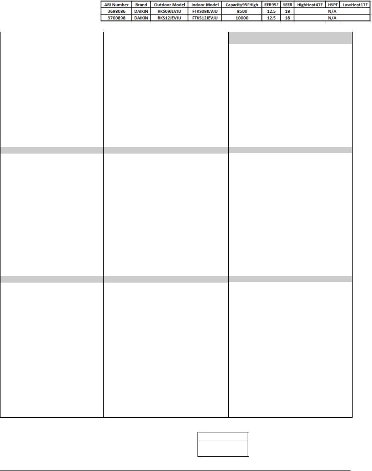
FTKS09JEVJU |
RKS09JEVJU |
|
|
|
FTKS12JEVJU |
RKS12JEVJU |
||
|
|
|
|||
|
|
Heat Pump |
FTXS09JEVJU |
RXS09JEVJU |
|
|
|
FTXS12JEVJU |
RXS12JEVJU |
||
|
|
|
|||
1. |
Power Supply .......................................................................................... |
|
|
3 |
|
2. |
Functions................................................................................................. |
|
|
4 |
|
3. |
Specifications .......................................................................................... |
|
|
5 |
|
|
3.1 |
Cooling Only............................................................................................. |
|
|
5 |
|
3.2 |
Heat Pump ............................................................................................... |
|
|
6 |
4. |
Dimensions ............................................................................................. |
|
|
7 |
|
|
4.1 |
Indoor Units .............................................................................................. |
|
|
7 |
|
4.2 |
Outdoor Units ........................................................................................... |
|
|
8 |
5. |
Wiring Diagrams...................................................................................... |
|
|
9 |
|
|
5.1 |
Indoor Units .............................................................................................. |
|
|
9 |
|
5.2 |
Outdoor Units ........................................................................................... |
|
|
9 |
6. |
Piping Diagrams.................................................................................... |
|
|
10 |
|
|
6.1 |
Indoor Units ............................................................................................ |
|
|
10 |
|
6.2 |
Outdoor Units ......................................................................................... |
|
|
11 |
7. |
Capacity Tables .................................................................................... |
|
|
12 |
|
|
7.1 |
Cooling Only........................................................................................... |
|
|
12 |
|
7.2 |
Heat Pump ............................................................................................. |
|
|
14 |
|
7.3 |
Capacity correction factor by the length of refrigerant piping ................ |
18 |
||
8. |
Operation Limit...................................................................................... |
|
|
19 |
|
9. |
Sound Level .......................................................................................... |
|
|
20 |
|
|
9.1 |
Measuring Location ................................................................................ |
|
|
20 |
|
9.2 |
Octave Band Level ................................................................................. |
|
|
21 |
10.Electric Characteristics.......................................................................... |
|
|
23 |
||
11.Installation Manual ................................................................................ |
|
|
24 |
||
|
11.1 |
Indoor Units ............................................................................................ |
|
|
24 |
|
11.2 |
Outdoor Units ......................................................................................... |
|
|
36 |
12. Safety Considerations .......................................................................... |
|
|
48 |
||
13.Optional Accessories ............................................................................ |
|
|
75 |
||
|
13.1 |
Option List .............................................................................................. |
|
|
75 |
Room Air Conditioners J-Series |
1 |

|
|
EDUS041011 |
13.2 |
<BRC944B2> Wired Remote Controller................................................. |
76 |
13.3 |
<KRP980B1> Interface Adaptor for Wired Remote Controller ............... |
90 |
13.4 |
<KPW937A4> Air Direction Adjustment Grille........................................ |
94 |
2 |
Room Air Conditioners J-Series |

EDUS041011 Power Supply
1. Power Supply
|
Indoor Units |
Outdoor Units |
Power Supply |
|
|
|
|
|
|
|
FTKS09JEVJU |
RKS09JEVJU |
|
|
|
|
|
|
|
The Single Split |
FTKS12JEVJU |
RKS12JEVJU |
1 , 208-230V, 60Hz |
|
Duct-Free System |
FTXS09JEVJU |
RXS09JEVJU |
||
|
||||
|
|
|
|
|
|
FTXS12JEVJU |
RXS12JEVJU |
|
|
|
|
|
|
Note:
Power Supply Intake ; Outdoor Unit
Room Air Conditioners J-Series |
3 |

Functions |
EDUS041011 |
2. Functions
Category |
Functions |
FTKS09/12JEVJU RKS09/12JEVJU |
FTXS09/12JEVJU RXS09/12JEVJU |
Category |
|
|
|
||||
Basic |
Inverter (with Inverter Power Control) |
|
|
Health & |
|
Function |
|
|
|
Clean |
|
Operation Limit for Cooling (°FDB) |
50~ |
50~ |
|||
|
|
||||
|
114.8 |
114.8 |
|
||
|
|
|
|||
|
|
|
|
|
|
|
Operation Limit for Heating (°FWB) |
— |
5~68 |
|
|
|
|
|
|
|
|
|
PAM Control |
|
|
|
|
|
|
|
|
|
|
Compressor |
Oval Scroll Compressor |
— |
— |
|
|
|
|
|
|
|
|
|
Swing Compressor |
|
|
|
|
|
|
|
|
|
|
|
Rotary Compressor |
— |
— |
|
|
|
|
|
|
|
|
|
Reluctance DC Motor |
|
|
|
|
|
|
|
|
|
|
Comfortable |
Power-Airflow Louver (Horizontal Blade) |
|
|
|
|
Airflow |
Power-Airflow Dual Louvers |
— |
— |
Timer |
|
|
|||||
|
|
|
|
|
|
|
Power-Airflow Diffuser |
— |
— |
|
|
|
Wide-Angle Fins (Vertical Blades) |
|
|
Worry Free |
|
|
|
|
|
“Reliability & |
|
|
Vertical Auto-Swing (Up and Down) |
|
|
||
|
Durability” |
||||
|
Horizontal Auto-Swing (Right and Left) |
— |
— |
|
|
|
|
|
|
|
|
|
3-D Airflow |
— |
— |
|
|
|
COMFORT AIRFLOW Operation |
|
|
Flexibility |
|
|
|
|
|
|
|
Comfort |
Auto Fan Speed |
|
|
|
|
Control |
|
|
|
|
|
Indoor Unit Quiet Operation |
|
|
|
||
|
|
||||
|
|
|
|
|
|
|
NIGHT QUIET Mode (Automatic) |
— |
— |
|
|
|
|
|
|
|
|
|
Outdoor Unit Quiet Operation (Manual) |
— |
— |
|
|
|
|
|
|
|
|
|
INTELLIGENT EYE Operation |
— |
— |
|
|
|
Quick Warming Function |
— |
|
Remote |
|
|
Control |
||||
|
Hot-Start Function |
— |
|
|
|
|
|
|
|
|
|
|
Automatic Defrosting |
— |
|
|
|
|
|
|
|
|
|
Operation |
Automatic Operation |
— |
|
|
|
|
Program Dry Function |
|
|
Remote |
|
|
|
|
|
Controller |
|
|
Fan Only |
|
|
||
Lifestyle |
New POWERFUL Operation |
— |
— |
|
|
Convenience |
(Non-Inverter) |
|
|||
|
|
|
|||
|
Inverter POWERFUL Operation |
|
|
|
|
|
Priority-Room Setting |
— |
— |
|
|
|
COOL / HEAT Mode Lock |
— |
— |
|
|
|
HOME LEAVE Operation |
— |
— |
|
|
|
ECONO Operation |
|
|
|
|
|
Indoor Unit ON/OFF Button |
|
|
|
|
|
Signal Receiving Sign |
|
|
|
|
|
Temperature Display |
— |
— |
|
|
|
Another Room Operation |
— |
— |
|
|
|
|
|
|
|
Note: : Holding Functions
— : No Functions
Functions |
FTKS09/12JEVJU RKS09/12JEVJU |
FTXS09/12JEVJU RXS09/12JEVJU |
|
|
|
||
Air-Purifying Filter |
— |
— |
|
|
|
|
|
Photocatalytic Deodorizing Filter |
— |
— |
|
|
|
|
|
Air-Purifying Filter with Photocatalytic |
— |
— |
|
Deodorizing Function |
|||
|
|
||
Titanium Apatite Photocatalytic |
|
|
|
Air-Purifying Filter |
|||
|
|
||
Air Filter (Prefilter) |
|
|
|
|
|
|
|
Wipe-clean Flat Panel |
|
|
|
|
|
|
|
Washable Grille |
— |
— |
|
|
|
|
|
Filter Cleaning Indicator |
— |
— |
|
|
|
|
|
Good-Sleep Cooling Operation |
— |
— |
|
24-Hour ON/OFF Timer |
|
|
|
|
|
|
|
NIGHT SET Mode |
|
|
|
Auto-Restart (after Power Failure) |
|
|
|
|
|
|
|
Self-Diagnosis (Digital, LED) Display |
|
|
|
|
|
|
|
Wiring Error Check |
— |
— |
|
|
|
|
|
Anti-Corrosion Treatment of Outdoor |
|
|
|
Heat Exchanger |
|||
|
|
||
Multi-Split / Split Type Compatible |
— |
— |
|
Indoor Unit |
|||
|
|
||
Flexible Voltage Correspondence |
— |
— |
|
|
|
|
|
High Ceiling Application |
— |
— |
|
|
|
|
|
Chargeless |
32.8ft |
32.8ft |
|
|
|
|
|
Either Side Drain (Right or Left) |
|
|
|
|
|
|
|
Power Selection |
— |
— |
|
5-Rooms Centralized Controller |
— |
— |
|
(Option) |
|||
|
|
||
Remote Control Adaptor |
— |
— |
|
(Normal Open-Pulse Contact) (Option) |
|||
|
|
||
Remote Control Adaptor |
— |
— |
|
(Normal Open Contact) (Option) |
|||
|
|
||
DIII-NET Compatible (Adaptor) (Option) |
— |
— |
|
Wireless |
|
|
|
|
|
|
|
Wired |
|
|
|
|
|
|
4 |
Room Air Conditioners J-Series |
EDUS041011 |
Specifications |
3. Specifications
3.1Cooling Only
Models |
Indoor Units |
|
FTKS09JEVJU |
FTKS12JEVJU |
|
60Hz 208-230V |
Outdoor Units |
|
RKS09JEVJU |
RKS12JEVJU |
|
Capacity |
|
kW |
2.49 (1.30~2.78) |
2.93 (1.3~3.52) |
|
|
Btu/h |
8,500 (4,400~9,500) |
10,000 (4,400~12,000) |
||
Rated (Min.~Max.) |
|||||
kal/h |
2,140 (1,120~2,390) |
2,520 (1,120~3,030) |
|||
|
|
||||
Running Current (Rated) |
A |
4.1-3.7 |
4.1-3.7 |
||
Power Consumption Rated (Min.~Max.) |
W |
680 (330~800) |
800 (330~1,180) |
||
Power Factor |
|
% |
79.7-79.9 |
93.8-94.0 |
|
COP (Rated) (Min.~Max.) |
W/W |
3.66 (3.94~3.48) |
3.66 (3.94~2.98) |
||
EER (Rated) (Min.~Max.) |
Btu/h·W |
12.50 (13.33~11.90) |
12.50 (13.33~10.20) |
||
Piping |
Liquid |
inch |
1/4 |
1/4 |
|
Gas |
inch |
3/8 |
3/8 |
||
Connections |
|||||
Drain |
inch |
5/8 |
5/8 |
||
|
|||||
Heat Insulation |
|
|
Both Liquid and Gas Pipes |
Both Liquid and Gas Pipes |
|
Max. Interunit Piping Length |
feet |
49.2 |
49.2 |
||
Max. Interunit Height Difference |
feet |
39.3 |
39.3 |
||
Chargeless |
|
feet |
32.8 |
32.8 |
|
Amount of Additional Charge of |
oz/ft |
0.22 |
0.22 |
||
Refrigerant |
|
||||
|
|
|
|
||
Indoor Units |
|
|
|
FTKS09JEVJU |
FTKS12JEVJU |
|
Front Panel Color |
|
White |
White |
|||
|
|
|
|
H |
9.2 (325) |
9.3 (328) |
Airflow Rate |
|
m³/min (cfm) |
M |
7.4 (261) |
7.7 (272) |
|
|
L |
5.3 (187) |
5.6 (198) |
|||
|
|
|
|
|||
|
|
|
|
SL |
4.0 (141) |
4.4 (155) |
|
|
Type |
|
Cross Flow Fan |
Cross Flow Fan |
|
Fan |
|
Motor Output |
W |
16 |
16 |
|
|
|
Speed |
Steps |
5 Steps, Quiet and Auto |
5 Steps, Quiet and Auto |
|
Air Direction Control |
|
Right, Left, Horizontal and Downward |
Right, Left, Horizontal and Downward |
|||
Air Filter |
|
|
|
Removable / Washable / Mildew Proof |
Removable / Washable / Mildew Proof |
|
Running Current (Rated) |
A |
0.20-0.18 |
0.20-0.18 |
|||
Power Consumption (Rated) |
W |
40 |
40 |
|||
Power Factor |
|
|
% |
96.2-96.6 |
96.2-96.6 |
|
Temperature Control |
|
Microcomputer Control |
Microcomputer Control |
|||
Dimensions (H×W×D) |
inch |
11-9/64×30-5/16×7-51/64 |
11-9/64×30-5/16×7-51/64 |
|||
Packaged Dimensions (H×W×D) |
inch |
10-17/64×33-7/32×13-15/32 |
10-17/64×33-7/32×13-15/32 |
|||
Weight |
|
|
Lbs |
16 |
16 |
|
Gross Weight |
|
|
Lbs |
24 |
24 |
|
Operation Sound |
|
H/M/L/SL |
dBA |
40 / 33 / 26 / 22 |
41 / 34 / 27 / 23 |
|
Sound Power |
|
|
dBA |
56 |
57 |
|
Outdoor Units |
|
|
RKS09JEVJU |
RKS12JEVJU |
|
Casing Color |
|
|
Ivory White |
Ivory White |
|
|
|
Type |
|
Hermetically Sealed Swing Type |
Hermetically Sealed Swing Type |
Compressor |
|
Model |
|
1YC23AEXD |
1YC23AEXD |
|
|
Motor Output |
W |
750 |
750 |
Refrigerant Oil |
|
Type |
|
FVC50K |
FVC50K |
|
Charge |
oz |
12.5 |
12.5 |
|
|
|
||||
Refrigerant |
|
Type |
|
R-410A |
R-410A |
|
Charge |
Lbs |
2.20 |
2.20 |
|
|
|
||||
Airflow Rate |
|
m³/min (cfm) |
H |
26.1 (921) |
26.1 (921) |
Fan |
|
Type |
|
Propeller |
Propeller |
|
Motor Output |
W |
33 |
33 |
|
|
|
||||
Running Current |
(Rated) |
A |
3.90-3.52 |
3.90-3.52 |
|
Power Consumption (Rated) |
W |
640 |
760 |
||
Power Factor |
|
% |
78.9-79.1 |
93.7-93.9 |
|
Starting Current |
|
A |
4.1 |
4.8 |
|
Dimensions (H×W×D) |
inch |
21-21/32×25-29/32×10-13/16 |
21-21/32×25-29/32×10-13/16 |
||
Packaged Dimensions (H×W×D) |
inch |
23-5/16×30-23/64×13-45/64 |
23-5/16×30-23/64×13-45/64 |
||
Weight |
|
Lbs |
66 |
66 |
|
Gross Weight |
|
Lbs |
75 |
75 |
|
Operation Sound |
|
dBA |
48 |
48 |
|
Sound Power |
|
dBA |
62 |
62 |
|
Drawing No. |
|
|
C: 3D066330B |
C: 3D066331B |
|
Note:
The data are based on the conditions shown in the table below.
Cooling |
Piping Length |
|
Indoor ; 80°FDB/67°FWB |
25ft |
|
Outdoor ; 95°FDB/75°FWB |
||
|
Conversion Formulae
kcal/h=kW×860 Btu/h=kW×3412 cfm=m³/min×35.3
Room Air Conditioners J-Series |
5 |

Specifications |
EDUS041011 |
3.2Heat Pump
Models |
|
Indoor Units |
|
FTXS09JEVJU |
FTXS12JEVJU |
|||||
|
|
|
|
RXS09JEVJU |
RXS12JEVJU |
|||||
60Hz 208-230V |
|
Outdoor Units |
|
|||||||
|
|
Cooling |
|
Heating |
Cooling |
|
Heating |
|||
|
|
|
|
|
|
|
||||
Capacity |
|
|
kW |
2.49 (1.30~2.78) |
|
2.93 (1.3~3.4) |
2.93 (1.3~3.52) |
|
3.52 (1.3~4.8) |
|
|
|
Btu/h |
8,500 (4,400~9,500) |
|
10,000 (4,400~11,600) |
10,000 (4,400~12,000) |
|
12,000 (4,400~16,400) |
||
Rated (Min.~Max.) |
|
|
||||||||
kal/h |
2,140 (1,120~2,390) |
|
2,520 (1,120~2,920) |
2,520 (1,120~3,030) |
|
3,030 (1,120~4,130) |
||||
|
|
|
|
|
|
|||||
Running Current (Rated) |
A |
4.1-3.7 |
|
4.0-3.6 |
4.1-3.7 |
|
4.8-4.3 |
|||
Power Consumption Rated (Min.~Max.) |
W |
680 (330~800) |
|
775 (310~840) |
800 (330~1,180) |
|
930 (310~1,500) |
|||
Power Factor |
|
|
% |
79.7-79.9 |
|
93.1-93.6 |
93.8-94.0 |
|
93.1-94.0 |
|
COP (Rated) (Min.~Max.) |
W/W |
3.66 (3.94~3.48) |
|
3.78 (4.19~4.05) |
3.66 (3.94~2.98) |
|
3.78 (4.19~3.20) |
|||
EER (Rated) (Min.~Max.) |
Btu/h·W |
12.50 (13.33~11.90) |
|
12.90 (14.19~13.81) |
12.50 (13.33~11.90) |
|
12.90 (14.19~10.90) |
|||
Piping |
|
Liquid |
inch |
|
|
1/4 |
1/4 |
|
||
|
Gas |
inch |
|
3/8 |
3/8 |
|
||||
Connections |
|
|
|
|||||||
|
Drain |
inch |
|
5/8 |
5/8 |
|
||||
|
|
|
|
|||||||
Heat Insulation |
|
|
|
|
Both Liquid and Gas Pipes |
Both Liquid and Gas Pipes |
||||
Max. Interunit Piping Length |
feet |
|
49.2 |
49.2 |
|
|||||
Max. Interunit Height Difference |
feet |
|
39.3 |
39.3 |
|
|||||
Chargeless |
|
|
feet |
|
32.8 |
32.8 |
|
|||
Amount of Additional Charge of |
oz/ft |
|
0.22 |
0.22 |
|
|||||
Refrigerant |
|
|
|
|
||||||
|
|
|
|
|
|
|
|
|
||
Indoor Units |
|
|
|
FTXS09JEVJU |
FTXS12JEVJU |
|||||
Front Panel Color |
|
|
|
|
White |
White |
|
|||
|
|
|
|
H |
9.2 (325) |
|
9.7 (342) |
9.3 (328) |
|
10.1 (357) |
Airflow Rate |
|
m³/min (cfm) |
M |
7.4 (261) |
|
8.1 (286) |
7.7 (272) |
|
8.4 (297) |
|
|
L |
5.3 (187) |
|
6.4 (226) |
5.6 (198) |
|
6.7 (237) |
|||
|
|
|
|
|
|
|||||
|
|
|
|
SL |
4.0 (141) |
|
5.6 (198) |
4.4 (155) |
|
5.9 (208) |
|
|
Type |
|
Cross Flow Fan |
Cross Flow Fan |
|||||
Fan |
|
Motor Output |
W |
|
16 |
16 |
|
|||
|
|
Speed |
Steps |
5 Steps, Quiet and Auto |
5 Steps, Quiet and Auto |
|||||
Air Direction Control |
|
Right, Left, Horizontal and Downward |
Right, Left, Horizontal and Downward |
|||||||
Air Filter |
|
|
|
Removable / Washable / Mildew Proof |
Removable / Washable / Mildew Proof |
|||||
Running Current (Rated) |
A |
|
0.20-0.18 |
0.20-0.18 |
||||||
Power Consumption (Rated) |
W |
|
40 |
40 |
|
|||||
Power Factor |
|
|
% |
|
96.2-96.6 |
96.2-96.6 |
||||
Temperature Control |
|
Microcomputer Control |
Microcomputer Control |
|||||||
Dimensions (H×W×D) |
inch |
11-9/64×30-5/16×7-51/64 |
11-9/64×30-5/16×7-51/64 |
|||||||
Packaged Dimensions (H×W×D) |
inch |
10-17/64×33-7/32×13-15/32 |
10-17/64×33-7/32×13-15/32 |
|||||||
Weight |
|
|
Lbs |
|
16 |
16 |
|
|||
Gross Weight |
|
|
Lbs |
|
24 |
24 |
|
|||
Operation Sound |
|
H/M/L/SL |
dBA |
40 / 33 / 26 / 22 |
|
40 / 34 / 28 / 25 |
41 / 34 / 27 / 23 |
|
41 / 35 / 29 / 26 |
|
Sound Power |
|
|
dBA |
|
56 |
57 |
|
|||
Outdoor Units |
|
|
|
RXS09JEVJU |
RXS12JEVJU |
|||||
Casing Color |
|
|
|
|
Ivory White |
Ivory White |
||||
|
|
Type |
|
Hermetically Sealed Swing Type |
Hermetically Sealed Swing Type |
|||||
Compressor |
|
Model |
|
1YC23AEXD |
1YC23AEXD |
|||||
|
|
Motor Output |
W |
|
750 |
750 |
|
|||
Refrigerant Oil |
|
Type |
|
|
FVC50K |
FVC50K |
|
|||
|
Charge |
oz |
|
12.5 |
12.5 |
|
||||
|
|
|
|
|||||||
Refrigerant |
|
Type |
|
|
R-410A |
R-410A |
|
|||
|
Charge |
Lbs |
|
2.20 |
2.20 |
|
||||
|
|
|
|
|||||||
Airflow Rate |
|
m³/min (cfm) |
H |
|
26.1 (921) |
26.1 (921) |
||||
Fan |
|
Type |
|
|
Propeller |
Propeller |
||||
|
Motor Output |
W |
|
33 |
33 |
|
||||
|
|
|
|
|||||||
Running Current |
(Rated) |
A |
3.90-3.52 |
|
3.80-3.42 |
3.90-3.52 |
|
4.60-4.12 |
||
Power Consumption (Rated) |
W |
640 |
|
735 |
760 |
|
890 |
|||
Power Factor |
|
|
% |
78.9-79.1 |
|
93.0-93.4 |
93.7-93.9 |
|
93.0-93.9 |
|
Starting Current |
|
|
A |
|
4.1 |
4.1 |
|
4.8 |
||
Dimensions (H×W×D) |
inch |
21-21/32×25-29/32×10-13/16 |
21-21/32×25-29/32×10-13/16 |
|||||||
Packaged Dimensions (H×W×D) |
inch |
23-5/16×30-23/64×13-45/64 |
23-5/16×30-23/64×13-45/64 |
|||||||
Weight |
|
|
Lbs |
|
68 |
68 |
|
|||
Gross Weight |
|
|
Lbs |
|
77 |
77 |
|
|||
Operation Sound |
|
|
dBA |
|
48 |
48 |
|
49 |
||
Sound Power |
|
|
dBA |
|
62 |
62 |
|
63 |
||
Drawing No. |
|
|
|
C: 3D066292B |
C: 3D066329B |
|||||
Note:
The data are based on the conditions shown in the table below. |
|
||
Cooling |
Heating |
|
Piping Length |
Indoor ; 80°FDB/67°FWB |
Indoor ; 70°FDB/60°FWB |
|
25ft |
Outdoor ; 95°FDB/75°FWB |
Outdoor ; 47°FDB/43°FWB |
|
|
|
|
||
Conversion Formulae
kcal/h=kW×860 Btu/h=kW×3412 cfm=m³/min×35.3
6 |
Room Air Conditioners J-Series |
EDUS041011 |
Dimensions |
4. Dimensions
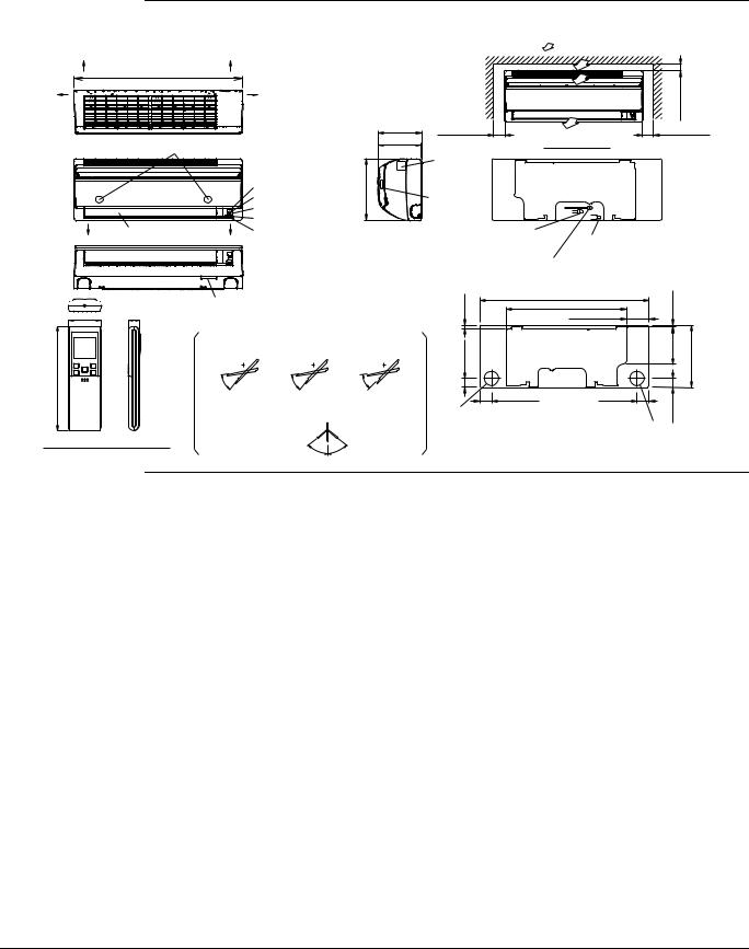
4.1Indoor Units
FTKS09/12JEVJU
THE MARK (→) SHOWS PIPING DIRECTION |
AIRFLOW (INDOOR) |
|
REAR
30-5/16(770mm)
LEFT 


 RIGHT
RIGHT
FRONT PANEL FIXING SCREWS
|
|
(INSIDE) |
|
|
SIGNAL RECEIVER |
|
|
OPERATION LAMP |
|
|
TIMER LAMP |
|
|
INDOOR UNIT ON/OFF SWITCH |
BOTTOM |
FLAPS |
ROOM TEMP. THERMISTOR |
|
|
(INSIDE) |
11-9/64(283mm)
MOUNTING PLATE |
|
|
3/16(30mm)MIN.-1 (SPACEFOR PERFORMANCE) |
|
INCLUDING |
|
|
|
|
7-7/8(200mm) |
1-15/16(50mm)MIN. |
|
|
1-15/16(50mm)MIN. |
|
|
|
||
7-51/64(198mm) |
(SPACE FOR |
REQUIRED SPACE |
(SPACE FOR |
|
|
MAINTENANCE) |
MAINTENANCE) |
||
|
|
|
||
|
GENERAL RATING |
|
|
|
|
NAME PLATE |
|
|
|
|
TERMINAL BLOCK |
|
|
|
|
WITH EARTH |
|
|
|
|
TERMINAL |
|
|
|
|
(INSIDE) |
|
|
|
|
GAS PIPE φ3/8(φ9.5mm) CuT |
|
|
|
|
(THE LENGTH OF PIPE OUTSIDE |
DRAIN HOSE |
|
|
|
THE UNIT : ABOUT 15-23/64(390mm)) |
|
||
|
(CONNECTING PART |
|
||
|
LIQUID PIPE φ1/4(φ6.4mm) CuT |
|
||
|
I.D. φ9/16(φ14mm) |
|
||
|
(THE LENGTH OF PIPE OUTSIDE |
O.D. φ5/8(φ16mm) |
|
|
|
THE UNIT : ABOUT 17-21/64(440mm)) |
THE HOSE LENGTH OF OUTSIDE |
||
|
|
|
THE UNIT IS ABOUT 17-23/32(450mm)) |
|


 SIGNAL TRANSMITTER
2-5/16(58mm) 11/16(18mm)
7-3/8(187mm)
WIRELESS REMOTE CONTROLLER
(ARC452A14)
MODEL NAME
PLATE
BLADE ANGLE
UP/DOWN (AUTOMATIC) |
|
|
COOLING |
DRY |
FAN |
5û |
5û |
5û |
45û |
45û |
45û |
|
RIGHT/LEFT (MANUAL) |
|
45û |
45û |
5/8(16mm) |
30-5/16(770mm) |
15/64(6mm) |
21-39/64(549mm) |
||
3-31/32(101mm) |
||
|
1-5/8(41.3mm) |
|
6-49/64(172mm) |
11-9/64(283mm) |
φ2-9/16(φ65mm) HOLE |
|
5/8(41.3mm)-1 |
|
2-9/64(54.5mm) |
2-1/8(54mm) |
|
|
WALL HOLE FOR EMBEDDED PIPING |
|
|
|
|
|
WALL HOLE |
|
STANDARD LOCATIONS OF WALL HOLES |
φ2-9/16(φ65mm) HOLE |
||
|
|
||
3D065952B
FTXS09/12JEVJU
THE MARK (→) SHOWS PIPING DIRECTION |
|
|
|
REAR |
|
|
30-5/16(770mm) |
|
LEFT |
|
RIGHT |
|
FRONT PANEL FIXING SCREWS |
|
|
(INSIDE) |
|
|
|
SIGNAL RECEIVER |
|
|
OPERATION LAMP |
|
|
TIMER LAMP |
|
|
INDOOR UNIT ON/OFF SWITCH |
BOTTOM |
FLAPS |
ROOM TEMP. THERMISTOR |
|
|
(INSIDE) |
11-9/64(283mm)
|
|
AIRFLOW (INDOOR) |
|
|
MOUNTING PLATE |
|
|
3/16(30mm)MIN.-1 (SPACEFOR PERFORMANCE) |
|
INCLUDING |
|
|
|
|
7-7/8(200mm) |
1-15/16(50mm)MIN. |
|
|
1-15/16(50mm)MIN. |
7-51/64(198mm) |
(SPACE FOR |
REQUIRED SPACE |
(SPACE FOR |
|
|
MAINTENANCE) |
MAINTENANCE) |
||
|
|
|
||
|
GENERAL RATING |
|
|
|
|
NAME PLATE |
|
|
|
|
TERMINAL BLOCK |
|
|
|
|
WITH EARTH |
|
|
|
|
TERMINAL |
|
|
|
|
(INSIDE) |
|
|
|
|
GAS PIPE φ3/8(φ9.5mm) CuT |
|
|
|
|
(THE LENGTH OF PIPE OUTSIDE |
DRAIN HOSE |
|
|
|
THE UNIT : ABOUT 15-23/64(390mm)) |
|
||
|
(CONNECTING PART |
|
||
|
|
|
|
|
|
LIQUID PIPE φ1/4(φ6.4mm) CuT |
I.D. φ9/16(φ14mm) |
|
|
|
O.D. φ5/8(φ16mm) |
|
||
|
(THE LENGTH OF PIPE OUTSIDE |
|
||
|
THE HOSE LENGTH OF OUTSIDE |
|||
|
THE UNIT : ABOUT 17-21/64(440mm)) |
|||
|
|
|
THE UNIT IS ABOUT 17-23/32(450mm)) |
|
SIGNAL TRANSMITTER |
MODEL NAME |
|
|
|
2-5/16(58mm) 11/16(18mm) |
PLATE |
|
|
|
|
|
|
|
|
|
|
BLADE ANGLE |
|
|
|
UP/DOWN (AUTOMATIC) |
|
|
|
3/8(187mm)- |
COOLING |
HEATING |
|
DRY |
45û |
45û |
|
45û |
|
|
5û |
15û |
5û |
|
7 |
|
|
|
|
|
FAN |
|
RIGHT/LEFT (MANUAL) |
|
|
5û |
|
|
|
WIRELESS REMOTE CONTROLLER |
45û |
|
45û |
45û |
(ARC452A12) |
|
|||
|
|
|
|
|
5/8(16mm) |
30-5/16(770mm) |
|
15/64(6mm) |
|
|
|
|
|
|
|
21-39/64(549mm) |
|
|
|
|
3-31/32(101mm) |
|
|
|
1-5/8(41.3mm) |
|
|
6-49/64(172mm) |
-9/64(283mm) |
|
|
|
5/8(41.3mm)-1 |
11 |
φ2-9/16(φ65mm) HOLE |
2-1/8(54mm) |
|
||
|
2-9/64(54.5mm) |
|
|
|
WALL HOLE FOR EMBEDDED PIPING |
|
|
WALL HOLE |
STANDARD LOCATIONS OF WALL HOLES |
φ2-9/16(φ65mm) HOLE |
|
|
|
3D065951B |
Room Air Conditioners J-Series |
7 |

Dimensions |
EDUS041011 |
4.2Outdoor Units
RKS09/12JEVJU, RXS09/12JEVJU
DRAIN OUTLET |
|
(I.D5/8 [φ15.9] HOSE FOR CONNECTION |
4-HOLES FOR ANCHOR BOLTS |
WITH DRAIN JOINT [ OPTION ] ) |
(M8 OR M10) |
9/16(40)-1 |
18-1/2(470) |
3-25/32(96) |
14-29/32(379) |
7/16(11) |
|
|
|
|
|
|
11-11/16(297) |
HANDLE |
BRAND NAME LABEL |
MANUFACTURE'S LABEL |
OUTDOOR AIR THERMISTOR |
10-13/16(275) |
5/16(8) |
15/32(12) |
25-29/32(658) |
1-31/32(50) |
|
|
|
21-21/32(550) |
|
|
|
MINIMUM SPACE FOR AIR PASSAGE |
WALL HEIGHT ON AIR OUTLET SIDE |
7/8(150)-5 |
|||
=LESS THAN 47-3/16(1200) |
|
||||
|
|
|
|
||
|
15/16(100) |
5-7/8(150) |
|
|
13/16(300) |
1-15/16(50) |
3- |
|
1-15/16(50) |
1-15/16(50) |
|
|
|
|
|
|
11- |
5/16(8)
SERVICE PORT
6-3/32(155)
LIQUID |
STOP VALVE |
1/4(φ6.4)CuT |
6-5/8(168) |
4-1/4(108) |
IN CASE OF REMOVING |
GAS STOP VALVE |
|
3/8(φ9.5)CuT |
||
STOP VALVE |
||
|
1-15/16(50) |
-15/16(100) |
|
3 |
UNIT = INCH(mm)
3D065923A
8 |
Room Air Conditioners J-Series |
EDUS041011 |
Wiring Diagrams |
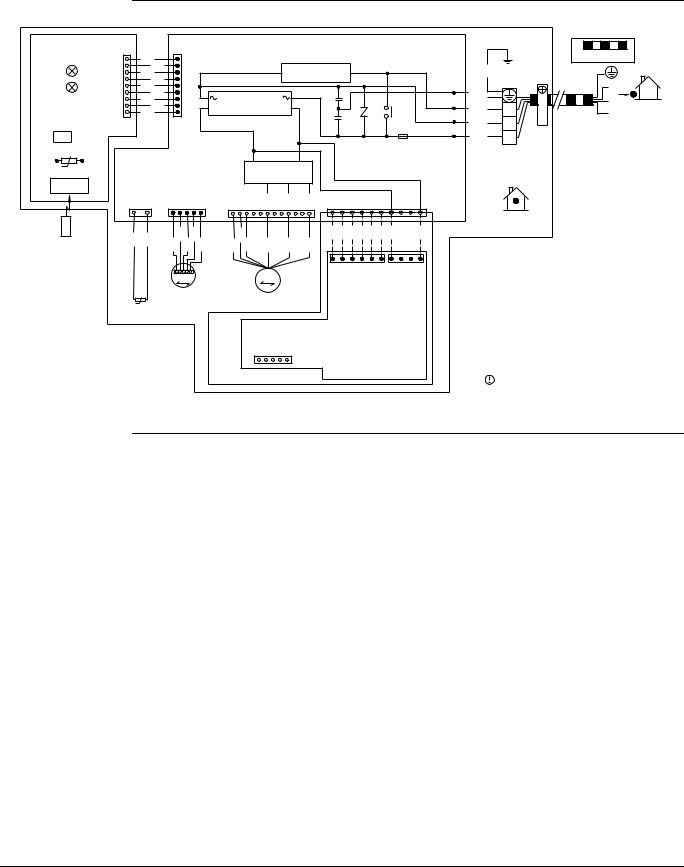
5. Wiring Diagrams
5.1Indoor Units
FTKS09/12JEVJU, FTXS09/12JEVJU
PCB 2 |
|
S27 |
|
S26 |
|
|
PCB 1 |
|
|
|
|
|
|
|
||
|
|
|
|
|
|
|
|
|
|
|
|
|
|
|||
|
|
|
|
|
|
|
|
|
|
|
|
|
|
|
||
|
|
1 |
BLK |
9 |
|
|
|
|
|
|
|
|
|
|
|
|
LED1 |
H1P |
|
BLK |
|
|
|
|
TRANSMISSION |
|
|
|
|
|
|||
|
BLK |
|
|
|
|
|
|
|
|
|
||||||
|
|
|
BLK |
|
|
|
|
|
CIRCUIT |
|
|
|
|
|
|
|
LED2 |
H2P |
|
BLK |
|
|
|
|
|
|
|
|
|
|
|
|
FG |
|
|
|
BLK |
|
|
|
|
|
|
|
|
|
|
|
|
|
|
|
|
BLK |
|
|
RECTIFIER |
|
|
|
|
|
|
|
|
H3 |
|
|
|
|
BLK |
|
|
+ |
|
|
|
|
|
|
|
|||
|
|
9 |
BLK |
1 |
|
Ð |
|
|
|
|
|
V1 |
|
MR10 |
H2 |
|
|
|
|
|
|
|
|
|
|
|
|
||||||
|
|
|
|
|
|
|
|
|
|
|
|
|
|
|
|
|
S1W |
|
|
|
|
|
|
|
|
|
|
|
|
|
|
|
H1 |
|
|
|
|
|
|
|
|
|
|
|
|
|
|
F1U |
|
|
|
|
|
|
|
|
|
|
|
|
|
|
|
|
|
|
|
tû |
|
|
|
|
|
|
|
|
|
|
|
|
|
|
3.15A |
|
R1T |
|
|
|
|
|
Ð |
|
|
+ |
|
|
|
|
|
|
|
|
|
|
|
|
|
IPM200 |
|
|
|
|
|
|
|
|
||
SIGNAL |
|
|
|
|
|
|
|
|
|
|
|
|
|
|||
RECEIVER |
|
|
|
|
|
|
|
|
|
|
|
|
|
|
|
|
|
|
1 |
2 |
1 |
5 |
1 |
6 |
9 |
12 |
1 |
|
S403 |
|
|
10 |
|
|
|
S32 |
S6 |
|
|
S200 |
|
|
|
BLK |
BLK |
BLK BLK |
BLK |
BLK BLK |
BLK |
|
WIRELESS |
BLK BLK |
BLK BLK |
ORG YLW BLU |
RED |
BLK |
WHT |
||||||||||
|
|
|
|
|
|
|
|
|
|
|
|
|
||||
|
BLK BLK BLK |
|
|
|
|
|
|
|
|
|
|
|
||||
REMOTE |
|
|
|
|
|
|
|
|
|
|
|
|
|
|
|
|
CONTROLLER |
|
|
|
|
|
|
|
|
6 |
|
|
|
1 |
4 |
1 |
|
|
|
|
|
|
|
|
|
|
|
|
|
|
||||
|
|
|
|
M |
|
|
M |
|
|
|
|
S602 |
|
|
S601 |
|
|
|
|
|
|
|
|
|
|
|
|
|
|
|
|
||
|
|
|
tû |
M1S |
|
|
M1F |
|
|
|
|
|
|
|
|
|
|
|
|
|
|
|
|
|
|
|
|
|
|
|
|
|
|
|
|
R2T |
|
|
|
|
|
|
|
|
|
|
|
|
|
|
NOTE) |
|
|
|
|
|
|
S21 |
|
|
|
|
|
|
|
|
|
1.PCB3 SHOWS THE CASE OF
OPTION CONNECTION. |
OPTION |
PCB 3 |
5.2Outdoor Units
GRN/YLW |
|
GRN |
|
RED |
3 |
WHT |
2 |
BLK |
1 |
|
X1M |
INDOOR
FIELD WIRING. |
||
3 |
|
|
2 |
OUTDOOR |
|
1 |
||
|
||
CAUTION
NOTE THAT OPERATION WILL RESTART AUTOMATICALLY IF THE MAIN POWER SUPPLY IS TURNED OFF AND THEN BACK ON AGAIN.
FG |
: FRAME GROUND |
||
F1U |
: FUSE |
||
H1~H3 |
: HARNESS |
||
H1P~H2P |
: PILOT LAMP |
||
M1F |
: FAN MOTOR |
||
M1S |
: SWING MOTOR |
||
PCB1~PCB3 |
: PRINTED CIRCUIT BOARD |
||
R1T, R2T |
: THERMISTOR |
||
S6~S602 |
: CONNECTOR |
||
S1W |
: OPERATION SWITCH |
||
X1M |
: TERMINAL STRIP |
||
|
|
|
: PROTECTIVE EARTH |
|
|
|
|
|
|
|
|
|
|
|
3D065939A |
RKS09/12JEVJU, RXS09/12JEVJU
Room Air Conditioners J-Series |
9 |
Piping Diagrams |
EDUS041011 |
6. Piping Diagrams
6.1Indoor Units
FTKS09/12JEVJU |
FTXS09/12JEVJU |
|
INDOOR UNIT |
|
|
HEAT EXCHANGER |
|
|
9/32CuT |
|
9/32CuT |
3/16CuT |
|
ON HEAT EXCH. |
9/32CuT |
|
|
THERMISTOR |
|
|
|
9/32CuT |
FIELD PIPING |
CROSS FLOW FAN |
|
|
|
|
(1/4CuT) |
M |
|
|
|
|
|
FAN MOTOR |
|
FIELD PIPING |
3/8CuT |
|
(3/8CuT) |
|
|
REFRIGERANT FLOW
 COOLING
4D066315
|
INDOOR UNIT |
|
|
HEAT EXCHANGER |
|
|
9/32CuT |
|
9/32CuT |
3/16CuT |
|
ON HEAT EXCH. |
9/32CuT |
|
|
THERMISTOR |
|
|
|
9/32CuT |
FIELD PIPING |
CROSS FLOW FAN |
|
|
|
|
(1/4CuT) |
M |
|
|
|
|
|
FAN MOTOR |
|
FIELD PIPING |
3/8CuT |
|
(3/8CuT) |
|
|
REFRIGERANT FLOW
 COOLING
 HEATING
4D066211
10 |
Room Air Conditioners J-Series |

EDUS041011 |
Piping Diagrams |
6.2Outdoor Units
RKS09/12JEVJU
OUTDOOR UNIT
|
9/32CuT HEAT EXCHANGER |
|
|
|
|
|
|
3/8CuT |
9/32CuT |
|
|
|
|
|
|
EXCHANGERHEAT THERMSTOR |
|
|
MUFFLER |
|
MOTOR OPERATED |
||
|
|
|
3/16CuT |
1/4CuT |
VALVE |
||
|
|
|
1/4CuT |
|
|||
|
|
|
3/16CuT |
|
|
|
|
|
|
FAN |
|
WITH |
|
|
|
|
|
M MOTOR |
FILTER |
|
|
|
|
|
PROPELLER FAN |
|
|
|
|
1/4CuT |
|
3/8CuT |
|
|
|
|
|
|
|
|
1/4CuT |
|
|
3/8CuT |
MUFFLER MUFFLER |
3/16CuT |
|
DISCHARGE PIPE |
|
|
|
3/8CuT |
|||
COMPRESSOR |
|
|
|||||
THERMISTOR |
|
|
|
||||
|
|
|
|
ACCUMULATOR |
|
|
|
STRAINER
FIELD PIPING
LIQUID STOP (1/4CuT) VALVE
REFRIGERANT FLOW
FIELD PIPING

 COOLING GAS STOP (3/8CuT)
VALVE
3D065937
RXS09/12JEVJU
OUTDOOR UNIT |
|
9/32CuT HEAT EXCHANGER |
OUTDOOR TEMPERATURE |
THERMISTOR |
3/8CuT
9/32CuT |
|
|
EXCHANGERHEAT THERMISTOR |
3/16CuT |
|
|
||
|
3/16CuT |
|
|
FAN |
MUFFLER |
M |
WITH |
|
MOTOR |
FILTER |
|
PROPELLER FAN
MOTOR OPERATED
VALVE
1/4CuT 1/4CuT
1/4CuT
3/8CuT |
3/8CuT |
|
|
|
|
|
|
1/4CuT |
FOUR WAY |
3/8CuT |
3/16CuT |
|
VALVE |
|
|
|
ON : HEATING |
|
|
DISCHARGE PIPE |
COMPRESSOR |
MUFFLER MUFFLER |
3/8CuT |
THERMISTOR |
|
|
|
|
|
ACCUMULATOR |
|
|
STRAINER |
FIELD PIPING |
|
|
|
|
||||||||||
|
|
|
|
|
||||||||||||
|
|
|
|
|
||||||||||||
|
|
|
|
|
|
|
|
|
|
|
|
|
|
|
|
|
|
LIQUID STOP |
(1/4CuT) |
|
|
|
|
||||||||||
|
VALVE |
|
|
|
|
|
||||||||||
|
|
|
|
|
|
|
|
|
|
|
|
FIELD PIPING |
REFRIGERANT FLOW |
|||
|
|
|
|
|
|
|
|
|
|
|
|
|
|
|
COOLING |
|
|
GAS STOP |
(3/8CuT) |
|
|
|
HEATING |
||||||||||
|
VALVE |
|
|
|
|
|||||||||||
|
|
|
|
|
|
|||||||||||
3D065936
Room Air Conditioners J-Series |
11 |

Capacity Tables |
EDUS041011 |
7. Capacity Tables
7.1Cooling Only
FTKS09JEVJU + RKS09JEVJU (60Hz 208/230V)
AFR |
9.2 |
|
|
BF |
0.27 |
|
|
Temp: Celsius / TC, SHC, PI: kW
INDOOR |
|
|
|
|
|
|
OUTDOOR TEMPERATURE (°CDB) |
|
|
|
|
|
|
||||||
|
|
|
|
|
|
|
|
|
|
|
|
|
|
|
|
|
|
|
|
EWB |
EDB |
|
20.0 |
|
|
25.0 |
|
|
30.0 |
|
|
32.0 |
|
|
35.0 |
|
|
40.0 |
|
|
|
|
|
|
|
|
|
|
|
|
|
|
|
|
|
|
|
|
|
°C |
°C |
TC |
SHC |
PI |
TC |
SHC |
PI |
TC |
SHC |
PI |
TC |
SHC |
PI |
TC |
SHC |
PI |
TC |
SHC |
PI |
|
|
|
|
|
|
|
|
|
|
|
|
|
|
|
|
|
|
|
|
14.0 |
20.0 |
2.21 |
1.77 |
0.49 |
2.21 |
1.77 |
0.55 |
2.21 |
1.77 |
0.61 |
2.21 |
1.77 |
0.64 |
2.20 |
1.76 |
0.67 |
2.09 |
1.71 |
0.72 |
|
|
|
|
|
|
|
|
|
|
|
|
|
|
|
|
|
|
|
|
16.0 |
22.0 |
2.67 |
1.90 |
0.52 |
2.55 |
1.85 |
0.57 |
2.43 |
1.79 |
0.63 |
2.39 |
1.77 |
0.65 |
2.32 |
1.74 |
0.68 |
2.20 |
1.69 |
0.73 |
|
|
|
|
|
|
|
|
|
|
|
|
|
|
|
|
|
|
|
|
18.0 |
25.0 |
2.78 |
1.99 |
0.53 |
2.66 |
1.94 |
0.58 |
2.55 |
1.90 |
0.63 |
2.50 |
1.88 |
0.65 |
2.43 |
1.85 |
0.68 |
2.32 |
1.80 |
0.73 |
|
|
|
|
|
|
|
|
|
|
|
|
|
|
|
|
|
|
|
|
19.4 |
26.7 |
2.84 |
2.11 |
0.53 |
2.72 |
2.06 |
0.58 |
2.61 |
2.01 |
0.63 |
2.56 |
1.99 |
0.65 |
2.49 |
1.97 |
0.68 |
2.37 |
1.92 |
0.73 |
22.0 |
30.0 |
3.01 |
2.04 |
0.53 |
2.89 |
1.99 |
0.58 |
2.78 |
1.95 |
0.63 |
2.73 |
1.94 |
0.65 |
2.66 |
1.91 |
0.68 |
2.55 |
1.87 |
0.73 |
|
|
|
|
|
|
|
|
|
|
|
|
|
|
|
|
|
|
|
|
24.0 |
32.0 |
3.12 |
1.98 |
0.54 |
3.01 |
1.95 |
0.59 |
2.89 |
1.91 |
0.64 |
2.85 |
1.89 |
0.66 |
2.78 |
1.87 |
0.69 |
2.66 |
1.83 |
0.74 |
|
|
|
|
|
|
|
|
|
|
|
|
|
|
|
|
|
|
|
|
Temp: Fahrenheit / TC, SHC: kBtu / PI: kW
INDOOR |
|
|
|
|
|
|
OUTDOOR TEMPERATURE (°FDB) |
|
|
|
|
|
|
||||||
|
|
|
|
|
|
|
|
|
|
|
|
|
|
|
|
|
|
|
|
EWB |
EDB |
|
68.0 |
|
|
77.0 |
|
|
86.0 |
|
|
90.0 |
|
|
95.0 |
|
|
104.0 |
|
|
|
|
|
|
|
|
|
|
|
|
|
|
|
|
|
|
|
|
|
°F |
°F |
TC |
SHC |
PI |
TC |
SHC |
PI |
TC |
SHC |
PI |
TC |
SHC |
PI |
TC |
SHC |
PI |
TC |
SHC |
PI |
|
|
|
|
|
|
|
|
|
|
|
|
|
|
|
|
|
|
|
|
57.2 |
68.0 |
7.54 |
5.17 |
0.46 |
7.54 |
5.17 |
0.53 |
7.54 |
5.17 |
0.60 |
7.54 |
5.17 |
0.63 |
7.52 |
5.15 |
0.67 |
7.13 |
4.83 |
0.68 |
|
|
|
|
|
|
|
|
|
|
|
|
|
|
|
|
|
|
|
|
60.8 |
71.6 |
9.10 |
6.14 |
0.52 |
8.70 |
5.79 |
0.57 |
8.31 |
5.46 |
0.63 |
8.15 |
5.33 |
0.65 |
7.91 |
5.14 |
0.68 |
7.52 |
4.83 |
0.68 |
|
|
|
|
|
|
|
|
|
|
|
|
|
|
|
|
|
|
|
|
64.4 |
77.0 |
9.49 |
6.18 |
0.53 |
9.10 |
5.85 |
0.58 |
8.70 |
5.53 |
0.63 |
8.54 |
5.40 |
0.65 |
8.30 |
5.22 |
0.68 |
7.91 |
4.92 |
0.69 |
|
|
|
|
|
|
|
|
|
|
|
|
|
|
|
|
|
|
|
|
67.0 |
80.0 |
9.69 |
6.26 |
0.53 |
9.29 |
5.93 |
0.58 |
8.90 |
5.62 |
0.63 |
8.74 |
5.50 |
0.65 |
8.50 |
5.32 |
0.68 |
8.10 |
5.03 |
0.69 |
71.6 |
86.0 |
10.27 |
6.02 |
0.53 |
9.88 |
5.71 |
0.58 |
9.48 |
5.42 |
0.63 |
9.32 |
5.31 |
0.65 |
9.09 |
5.15 |
0.68 |
8.69 |
4.88 |
0.69 |
|
|
|
|
|
|
|
|
|
|
|
|
|
|
|
|
|
|
|
|
75.2 |
89.6 |
10.67 |
5.81 |
0.54 |
10.27 |
5.52 |
0.59 |
9.87 |
5.25 |
0.64 |
9.72 |
5.15 |
0.66 |
9.48 |
4.99 |
0.69 |
9.08 |
4.74 |
0.69 |
|
|
|
|
|
|
|
|
|
|
|
|
|
|
|
|
|
|
|
|
Symbols
AFR |
: Airflow rate |
(m3/min.) |
BF |
: Bypass factor |
|
EWB |
: Entering wet bulb temp. |
(°C) / (°F) |
EDB |
: Entering dry bulb temp. |
(°C) / (°F) |
TC |
: Total capacity |
(kW) / (kBtu/h) |
SHC |
: Sensible heating capacity |
(kW) / (kBtu/h) |
PI |
: Power input |
(kW) |
Note:
1.Ratings shown are net capacities which include a deduction for indoor fan motor heat.
2. shows nominal (rated) capacities and power input.
3.TC, PI and SHC must be calculated by interpolation using the figures in the above tables. (Figures out of the tables should not be used for calculation.)
4.About SHC which are not mentioned on the table, please calculate them with around values in direct proportion.
5.Capacities are based on the following conditions. Corresponding refrigerant piping length : 25ft Level difference : 0ft
6.Airflow rate (AFR) and Bypass factor (BF) are tabulated above table.
3D066175
12 |
Room Air Conditioners J-Series |

EDUS041011 |
|
|
|
|
|
|
|
|
|
|
|
|
|
|
|
|
|
Capacity Tables |
|||||||
|
|
|
|
|
|
|
|
|
|
|
|
|
|
|
|
|
|
|
|
|
|
|
|||
FTKS12JEVJU + RKS12JEVJU |
|
|
|
|
|
|
|
|
|
|
|
|
|
|
|
||||||||||
(60Hz 208/230V) |
|
|
|
|
|
|
|
|
|
|
|
|
|
|
|
|
|
|
|
|
|
||||
|
|
|
|
|
|
|
|
|
|
|
|
|
|
|
|
|
|
|
|
|
|
|
|
|
|
AFR |
|
9.3 |
|
|
|
|
|
|
|
|
|
|
|
|
|
|
|
|
|
|
|
||||
|
|
|
|
|
|
|
|
|
|
|
|
|
|
|
|
|
|
|
|
|
|
|
|
|
|
BF |
|
|
0.27 |
|
|
|
|
|
|
|
|
|
|
|
|
|
|
|
|
|
|
|
|||
|
|
|
|
|
|
|
|
|
|
|
|
|
|
|
|
|
|
|
|
|
|
|
|||
Temp: Celsius / TC, SHC, PI: kW |
|
|
|
|
|
|
|
|
|
|
|
|
|
|
|
|
|||||||||
|
|
|
|
|
|
|
|
|
|
|
|
|
|
|
|
|
|
|
|
|
|
|
|
|
|
INDOOR |
|
|
|
|
|
|
|
|
|
|
OUTDOOR TEMPERATURE (°CDB) |
|
|
|
|
|
|
|
|||||||
|
|
|
|
|
|
|
|
|
|
|
|
|
|
|
|
|
|
|
|
|
|
|
|
|
|
EWB |
|
EDB |
|
|
20.0 |
|
|
|
|
25.0 |
|
|
30.0 |
|
|
32.0 |
|
|
35.0 |
|
|
40.0 |
|
|
|
|
|
|
|
|
|
|
|
|
|
|
|
|
|
|
|
|
|
|
|
|
|
|
|
|
|
°C |
|
°C |
|
TC |
|
SHC |
|
PI |
|
TC |
SHC |
PI |
TC |
SHC |
PI |
TC |
SHC |
PI |
TC |
SHC |
PI |
TC |
SHC |
PI |
|
|
|
|
|
|
|
|
|
|
|
|
|
|
|
|
|
|
|
|
|
|
|
|
|
|
|
14.0 |
|
20.0 |
|
2.22 |
|
1.77 |
|
0.54 |
|
2.22 |
1.77 |
0.61 |
2.22 |
1.77 |
0.69 |
2.22 |
1.77 |
0.72 |
2.22 |
1.77 |
0.76 |
2.22 |
1.77 |
0.84 |
|
|
|
|
|
|
|
|
|
|
|
|
|
|
|
|
|
|
|
|
|
|
|
|
|
|
|
16.0 |
|
22.0 |
|
2.97 |
|
2.05 |
|
0.60 |
|
2.97 |
2.05 |
0.67 |
2.86 |
1.99 |
0.74 |
2.81 |
1.97 |
0.76 |
2.73 |
1.93 |
0.79 |
2.59 |
1.87 |
0.85 |
|
|
|
|
|
|
|
|
|
|
|
|
|
|
|
|
|
|
|
|
|
|
|
|
|
|
|
18.0 |
|
25.0 |
|
3.27 |
|
2.22 |
|
0.62 |
|
3.14 |
2.15 |
0.68 |
3.00 |
2.09 |
0.74 |
2.94 |
2.07 |
0.76 |
2.86 |
2.03 |
0.80 |
2.73 |
1.98 |
0.86 |
|
|
|
|
|
|
|
|
|
|
|
|
|
|
|
|
|
|
|
|
|
|
|
|
|
|
|
19.4 |
|
26.7 |
|
3.34 |
|
2.33 |
|
0.62 |
|
3.20 |
2.27 |
0.68 |
3.07 |
2.21 |
0.74 |
3.01 |
2.19 |
0.76 |
2.93 |
2.15 |
0.80 |
2.79 |
2.10 |
0.86 |
|
22.0 |
|
30.0 |
|
3.54 |
|
2.24 |
|
0.63 |
|
3.41 |
2.19 |
0.69 |
3.27 |
2.14 |
0.75 |
3.21 |
2.12 |
0.77 |
3.13 |
2.09 |
0.81 |
3.00 |
2.04 |
0.86 |
|
|
|
|
|
|
|
|
|
|
|
|
|
|
|
|
|
|
|
|
|
|
|
|
|
|
|
24.0 |
|
32.0 |
|
3.68 |
|
2.18 |
|
0.63 |
|
3.54 |
2.13 |
0.69 |
3.40 |
2.08 |
0.75 |
3.35 |
2.07 |
0.77 |
3.27 |
2.04 |
0.81 |
3.13 |
1.99 |
0.87 |
|
|
|
|
|
|
|
|
|
|
|
|
|
|
|
|
|
|
|
|
|
|
|||||
Temp: Fahrenheit / TC, SHC: kBtu / PI: kW |
|
|
|
|
|
|
|
|
|
|
|
|
|
|
|||||||||||
|
|
|
|
|
|
|
|
|
|
|
|
|
|
|
|
|
|
||||||||
INDOOR |
|
|
|
|
|
|
|
|
|
|
OUTDOOR TEMPERATURE (°FDB) |
|
|
|
|
|
|
|
|||||||
|
|
|
|
|
|
|
|
|
|
|
|
|
|
|
|
|
|
|
|
|
|
|
|
||
EWB |
|
EDB |
|
|
68.0 |
|
|
|
|
77.0 |
|
|
86.0 |
|
|
90.0 |
|
|
95.0 |
|
|
104.0 |
|
|
|
|
|
|
|
|
|
|
|
|
|
|
|
|
|
|
|
|
|
|
|
|
|
|
|
|
|
°F |
|
°F |
|
TC |
|
SHC |
|
PI |
|
TC |
SHC |
PI |
TC |
SHC |
PI |
TC |
SHC |
PI |
TC |
SHC |
PI |
TC |
SHC |
PI |
|
|
|
|
|
|
|
|
|
|
|
|
|
|
|
|
|
|
|
|
|
|
|
|
|
|
|
57.2 |
|
68.0 |
|
7.58 |
|
5.20 |
|
0.48 |
|
7.58 |
5.20 |
0.55 |
7.58 |
5.20 |
0.62 |
7.58 |
5.20 |
0.65 |
7.58 |
5.20 |
0.70 |
7.58 |
5.20 |
0.74 |
|
|
|
|
|
|
|
|
|
|
|
|
|
|
|
|
|
|
|
|
|
|
|
|
|
|
|
60.8 |
|
71.6 |
|
10.14 |
|
7.10 |
|
0.59 |
|
10.14 |
7.10 |
0.67 |
9.77 |
6.75 |
0.74 |
9.59 |
6.58 |
0.76 |
9.31 |
6.32 |
0.79 |
8.84 |
5.90 |
0.80 |
|
|
|
|
|
|
|
|
|
|
|
|
|
|
|
|
|
|
|
|
|
|
|
|
|
|
|
64.4 |
|
77.0 |
|
11.17 |
|
7.73 |
|
0.62 |
|
10.70 |
7.27 |
0.68 |
10.24 |
6.83 |
0.74 |
10.05 |
6.66 |
0.76 |
9.77 |
6.42 |
0.80 |
9.30 |
6.02 |
0.81 |
|
|
|
|
|
|
|
|
|
|
|
|
|
|
|
|
|
|
|
|
|
|
|
|
|
|
|
67.0 |
|
80.0 |
|
11.40 |
|
7.81 |
|
0.62 |
|
10.93 |
7.36 |
0.68 |
10.47 |
6.93 |
0.74 |
10.28 |
6.76 |
0.76 |
10.00 |
6.52 |
0.80 |
9.53 |
6.12 |
0.81 |
|
71.6 |
|
86.0 |
|
12.09 |
|
7.54 |
|
0.63 |
|
11.62 |
7.12 |
0.69 |
11.16 |
6.72 |
0.75 |
10.97 |
6.56 |
0.77 |
10.69 |
6.33 |
0.81 |
10.23 |
5.97 |
0.81 |
|
|
|
|
|
|
|
|
|
|
|
|
|
|
|
|
|
|
|
|
|
|
|
|
|
|
|
75.2 |
|
89.6 |
|
12.55 |
|
7.30 |
|
0.63 |
|
12.08 |
6.90 |
0.69 |
11.62 |
6.52 |
0.75 |
11.43 |
6.37 |
0.77 |
11.15 |
6.16 |
0.81 |
10.69 |
5.81 |
0.82 |
|
|
|
|
|
|
|
|
|
|
|
|
|
|
|
|
|
|
|
|
|
|
|
|
|
|
|
Symbols
AFR |
: Airflow rate |
(m3/min.) |
BF |
: Bypass factor |
|
EWB |
: Entering wet bulb temp. |
(°C) / (°F) |
EDB |
: Entering dry bulb temp. |
(°C) / (°F) |
TC |
: Total capacity |
(kW) / (kBtu/h) |
SHC |
: Sensible heating capacity |
(kW) / (kBtu/h) |
PI |
: Power input |
(kW) |
Note:
1.Ratings shown are net capacities which include a deduction for indoor fan motor heat.
2. shows nominal (rated) capacities and power input.
3.TC, PI and SHC must be calculated by interpolation using the figures in the above tables. (Figures out of the tables should not be used for calculation.)
4.About SHC which are not mentioned on the table, please calculate them with around values in direct proportion.
5.Capacities are based on the following conditions. Corresponding refrigerant piping length : 25ft Level difference : 0ft
6.Airflow rate (AFR) and Bypass factor (BF) are tabulated above table.
3D066176
Room Air Conditioners J-Series |
13 |

Capacity Tables |
EDUS041011 |
7.2Heat Pump
FTXS09JEVJU + RXS09JEVJU (60Hz 208/230V)
Cooling
AFR |
9.2 |
|
|
BF |
0.27 |
|
|
Temp: Celsius / TC, SHC, PI: kW
INDOOR |
|
|
|
|
|
|
OUTDOOR TEMPERATURE (°CDB) |
|
|
|
|
|
|
||||||
|
|
|
|
|
|
|
|
|
|
|
|
|
|
|
|
|
|
|
|
EWB |
EDB |
|
20.0 |
|
|
25.0 |
|
|
30.0 |
|
|
32.0 |
|
|
35.0 |
|
|
40.0 |
|
|
|
|
|
|
|
|
|
|
|
|
|
|
|
|
|
|
|
|
|
°C |
°C |
TC |
SHC |
PI |
TC |
SHC |
PI |
TC |
SHC |
PI |
TC |
SHC |
PI |
TC |
SHC |
PI |
TC |
SHC |
PI |
|
|
|
|
|
|
|
|
|
|
|
|
|
|
|
|
|
|
|
|
14.0 |
20.0 |
2.21 |
1.77 |
0.49 |
2.21 |
1.77 |
0.55 |
2.21 |
1.77 |
0.61 |
2.21 |
1.77 |
0.64 |
2.20 |
1.76 |
0.67 |
2.09 |
1.71 |
0.72 |
|
|
|
|
|
|
|
|
|
|
|
|
|
|
|
|
|
|
|
|
16.0 |
22.0 |
2.67 |
1.90 |
0.52 |
2.55 |
1.85 |
0.57 |
2.43 |
1.79 |
0.63 |
2.39 |
1.77 |
0.65 |
2.32 |
1.74 |
0.68 |
2.20 |
1.69 |
0.73 |
|
|
|
|
|
|
|
|
|
|
|
|
|
|
|
|
|
|
|
|
18.0 |
25.0 |
2.78 |
1.99 |
0.53 |
2.66 |
1.94 |
0.58 |
2.55 |
1.90 |
0.63 |
2.50 |
1.88 |
0.65 |
2.43 |
1.85 |
0.68 |
2.32 |
1.80 |
0.73 |
|
|
|
|
|
|
|
|
|
|
|
|
|
|
|
|
|
|
|
|
19.4 |
26.7 |
2.84 |
2.11 |
0.53 |
2.72 |
2.06 |
0.58 |
2.61 |
2.01 |
0.63 |
2.56 |
1.99 |
0.65 |
2.49 |
1.97 |
0.68 |
2.37 |
1.92 |
0.73 |
22.0 |
30.0 |
3.01 |
2.04 |
0.53 |
2.89 |
1.99 |
0.58 |
2.78 |
1.95 |
0.63 |
2.73 |
1.94 |
0.65 |
2.66 |
1.91 |
0.68 |
2.55 |
1.87 |
0.73 |
|
|
|
|
|
|
|
|
|
|
|
|
|
|
|
|
|
|
|
|
24.0 |
32.0 |
3.12 |
1.98 |
0.54 |
3.01 |
1.95 |
0.59 |
2.89 |
1.91 |
0.64 |
2.85 |
1.89 |
0.66 |
2.78 |
1.87 |
0.69 |
2.66 |
1.83 |
0.74 |
|
|
|
|
|
|
|
|
|
|
|
|
|
|
|
|
|
|
|
|
Temp: Fahrenheit / TC, SHC: kBtu / PI: kW
INDOOR |
|
|
|
|
|
|
OUTDOOR TEMPERATURE (°FDB) |
|
|
|
|
|
|
||||||
|
|
|
|
|
|
|
|
|
|
|
|
|
|
|
|
|
|
|
|
EWB |
EDB |
|
68.0 |
|
|
77.0 |
|
|
86.0 |
|
|
90.0 |
|
|
95.0 |
|
|
104.0 |
|
|
|
|
|
|
|
|
|
|
|
|
|
|
|
|
|
|
|
|
|
°F |
°F |
TC |
SHC |
PI |
TC |
SHC |
PI |
TC |
SHC |
PI |
TC |
SHC |
PI |
TC |
SHC |
PI |
TC |
SHC |
PI |
|
|
|
|
|
|
|
|
|
|
|
|
|
|
|
|
|
|
|
|
57.2 |
68.0 |
7.54 |
5.17 |
0.46 |
7.54 |
5.17 |
0.53 |
7.54 |
5.17 |
0.60 |
7.54 |
5.17 |
0.63 |
7.52 |
5.15 |
0.67 |
7.13 |
4.83 |
0.68 |
|
|
|
|
|
|
|
|
|
|
|
|
|
|
|
|
|
|
|
|
60.8 |
71.6 |
9.10 |
6.14 |
0.52 |
8.70 |
5.79 |
0.57 |
8.31 |
5.46 |
0.63 |
8.15 |
5.33 |
0.65 |
7.91 |
5.14 |
0.68 |
7.52 |
4.83 |
0.68 |
|
|
|
|
|
|
|
|
|
|
|
|
|
|
|
|
|
|
|
|
64.4 |
77.0 |
9.49 |
6.18 |
0.53 |
9.10 |
5.85 |
0.58 |
8.70 |
5.53 |
0.63 |
8.54 |
5.40 |
0.65 |
8.30 |
5.22 |
0.68 |
7.91 |
4.92 |
0.69 |
|
|
|
|
|
|
|
|
|
|
|
|
|
|
|
|
|
|
|
|
67.0 |
80.0 |
9.69 |
6.26 |
0.53 |
9.29 |
5.93 |
0.58 |
8.90 |
5.62 |
0.63 |
8.74 |
5.50 |
0.65 |
8.50 |
5.32 |
0.68 |
8.10 |
5.03 |
0.69 |
71.6 |
86.0 |
10.27 |
6.02 |
0.53 |
9.88 |
5.71 |
0.58 |
9.48 |
5.42 |
0.63 |
9.32 |
5.31 |
0.65 |
9.09 |
5.15 |
0.68 |
8.69 |
4.88 |
0.69 |
|
|
|
|
|
|
|
|
|
|
|
|
|
|
|
|
|
|
|
|
75.2 |
89.6 |
10.67 |
5.81 |
0.54 |
10.27 |
5.52 |
0.59 |
9.87 |
5.25 |
0.64 |
9.72 |
5.15 |
0.66 |
9.48 |
4.99 |
0.69 |
9.08 |
4.74 |
0.69 |
|
|
|
|
|
|
|
|
|
|
|
|
|
|
|
|
|
|
|
|
Heating
AFR |
9.7 |
|
|
Temp: Celsius / TC, SHC, PI: kW
INDOOR |
|
|
|
OUTDOOR TEMPERATURE (°CWB) |
|
|
|
|
||||||
|
|
|
|
|
|
|
|
|
|
|
|
|
|
|
EDB |
–15.0 |
–10.0 |
–5.0 |
|
0 |
|
6.0 |
10.0 |
||||||
|
|
|
|
|
|
|
|
|
|
|
|
|
|
|
°C |
TC |
PI |
TC |
PI |
TC |
PI |
TC |
|
PI |
TC |
|
PI |
TC |
PI |
|
|
|
|
|
|
|
|
|
|
|
|
|
|
|
15.0 |
1.40 |
0.50 |
1.68 |
0.52 |
1.96 |
0.55 |
2.63 |
|
0.72 |
3.03 |
|
0.76 |
3.30 |
0.78 |
|
|
|
|
|
|
|
|
|
|
|
|
|
|
|
21.1 |
1.31 |
0.51 |
1.59 |
0.54 |
1.87 |
0.56 |
2.53 |
|
0.74 |
2.93 |
|
0.78 |
3.19 |
0.80 |
22.0 |
1.27 |
0.52 |
1.56 |
0.54 |
1.84 |
0.57 |
2.49 |
|
0.74 |
2.89 |
|
0.78 |
3.15 |
0.81 |
|
|
|
|
|
|
|
|
|
|
|
|
|
|
|
24.0 |
1.24 |
0.52 |
1.52 |
0.55 |
1.80 |
0.58 |
2.45 |
|
0.75 |
2.85 |
|
0.79 |
3.11 |
0.81 |
|
|
|
|
|
|
|
|
|
|
|
|
|
|
|
25.0 |
1.22 |
0.53 |
1.50 |
0.55 |
1.79 |
0.58 |
2.43 |
|
0.75 |
2.83 |
|
0.79 |
3.09 |
0.82 |
|
|
|
|
|
|
|
|
|
|
|
|
|
|
|
27.0 |
1.19 |
0.53 |
1.47 |
0.56 |
1.75 |
0.58 |
2.39 |
|
0.76 |
2.79 |
|
0.80 |
3.05 |
0.82 |
|
|
|
|
|
|
|
|
|
|
|
|
|
|
|
Temp: Fahrenheit / TC, SHC: kBtu / PI: kW
INDOOR |
|
|
|
|
OUTDOOR TEMPERATURE (°FWB) |
|
|
|
|||||
|
|
|
|
|
|
|
|
|
|
|
|
|
|
EDB |
|
5.0 |
14.0 |
23.0 |
32.0 |
43.0 |
50.0 |
||||||
|
|
|
|
|
|
|
|
|
|
|
|
|
|
°F |
TC |
|
PI |
TC |
PI |
TC |
PI |
TC |
PI |
TC |
PI |
TC |
PI |
|
|
|
|
|
|
|
|
|
|
|
|
|
|
59.0 |
4.76 |
|
0.50 |
5.72 |
0.52 |
6.68 |
0.55 |
8.99 |
0.72 |
10.35 |
0.76 |
11.25 |
0.78 |
|
|
|
|
|
|
|
|
|
|
|
|
|
|
70.0 |
4.47 |
|
0.51 |
5.43 |
0.54 |
6.39 |
0.56 |
8.64 |
0.74 |
10.00 |
0.78 |
10.90 |
0.80 |
71.6 |
4.35 |
|
0.52 |
5.31 |
0.54 |
6.27 |
0.57 |
8.51 |
0.74 |
9.86 |
0.78 |
10.77 |
0.81 |
|
|
|
|
|
|
|
|
|
|
|
|
|
|
75.2 |
4.23 |
|
0.52 |
5.19 |
0.55 |
6.15 |
0.58 |
8.37 |
0.75 |
9.72 |
0.79 |
10.63 |
0.81 |
|
|
|
|
|
|
|
|
|
|
|
|
|
|
77.0 |
4.18 |
|
0.53 |
5.14 |
0.55 |
6.10 |
0.58 |
8.30 |
0.75 |
9.65 |
0.79 |
10.56 |
0.82 |
|
|
|
|
|
|
|
|
|
|
|
|
|
|
80.6 |
4.06 |
|
0.53 |
5.02 |
0.56 |
5.98 |
0.58 |
8.16 |
0.76 |
9.52 |
0.80 |
10.42 |
0.82 |
|
|
|
|
|
|
|
|
|
|
|
|
|
|
14 |
Room Air Conditioners J-Series |

EDUS041011 |
Capacity Tables |
Symbols
AFR |
: Airflow rate |
(m3/min.) |
BF |
: Bypass factor |
|
EWB |
: Entering wet bulb temp. |
(°C) / (°F) |
EDB |
: Entering dry bulb temp. |
(°C) / (°F) |
TC |
: Total capacity |
(kW) / (kBtu/h) |
SHC |
: Sensible heating capacity |
(kW) / (kBtu/h) |
PI |
: Power input |
(kW) |
Note:
1.Ratings shown are net capacities which include a deduction for indoor fan motor heat.
2. shows nominal (rated) capacities and power input.
3.TC, PI and SHC must be calculated by interpolation using the figures in the above tables. (Figures out of the tables should not be used for calculation.)
4.About SHC which are not mentioned on the table, please calculate them with around values in direct proportion.
5.Capacities are based on the following conditions. Corresponding refrigerant piping length : 25ft Level difference : 0ft
6.Airflow rate (AFR) and Bypass factor (BF) are tabulated above table.
3D066177
Room Air Conditioners J-Series |
15 |

Capacity Tables |
|
|
|
|
|
|
|
|
|
|
|
|
|
|
|
|
|
|
|
|
EDUS041011 |
||||||
|
|
|
|
|
|
|
|
|
|
|
|
|
|
|
|
|
|
|
|
|
|
|
|
|
|||
FTXS12JEVJU + RXS12JEVJU |
|
|
|
|
|
|
|
|
|
|
|
|
|
|
|
|
|||||||||||
(60Hz 208/230V) |
|
|
|
|
|
|
|
|
|
|
|
|
|
|
|
|
|
|
|
|
|
|
|
||||
Cooling |
|
|
|
|
|
|
|
|
|
|
|
|
|
|
|
|
|
|
|
|
|
|
|
|
|||
AFR |
|
9.3 |
|
|
|
|
|
|
|
|
|
|
|
|
|
|
|
|
|
|
|
|
|
||||
|
|
|
|
|
|
|
|
|
|
|
|
|
|
|
|
|
|
|
|
|
|
|
|
|
|
|
|
|
BF |
0.27 |
|
|
|
|
|
|
|
|
|
|
|
|
|
|
|
|
|
|
|
|
|
||||
|
|
|
|
|
|
|
|
|
|
|
|
|
|
|
|
|
|
|
|
|
|
|
|
|
|||
Temp: Celsius / TC, SHC, PI: kW |
|
|
|
|
|
|
|
|
|
|
|
|
|
|
|
|
|
||||||||||
|
|
|
|
|
|
|
|
|
|
|
|
|
|
|
|
|
|
|
|
|
|
|
|
|
|
||
INDOOR |
|
|
|
|
|
|
|
|
|
|
|
OUTDOOR TEMPERATURE (°CDB) |
|
|
|
|
|
|
|
||||||||
|
|
|
|
|
|
|
|
|
|
|
|
|
|
|
|
|
|
|
|
|
|
|
|
|
|
|
|
EWB |
|
EDB |
|
|
20.0 |
|
|
|
|
|
25.0 |
|
|
30.0 |
|
|
32.0 |
|
|
35.0 |
|
|
40.0 |
|
|
||
|
|
|
|
|
|
|
|
|
|
|
|
|
|
|
|
|
|
|
|
|
|
|
|
|
|
|
|
°C |
|
°C |
|
TC |
|
SHC |
|
|
PI |
|
TC |
SHC |
PI |
TC |
|
SHC |
PI |
TC |
SHC |
PI |
TC |
SHC |
PI |
TC |
SHC |
PI |
|
|
|
|
|
|
|
|
|
|
|
|
|
|
|
|
|
|
|
|
|
|
|
|
|
|
|
|
|
14.0 |
|
20.0 |
|
2.22 |
|
1.77 |
|
0.54 |
|
2.22 |
1.77 |
0.61 |
2.22 |
|
1.77 |
0.69 |
2.22 |
1.77 |
0.72 |
2.22 |
1.77 |
0.76 |
2.22 |
1.77 |
0.84 |
|
|
|
|
|
|
|
|
|
|
|
|
|
|
|
|
|
|
|
|
|
|
|
|
|
|
|
|
|
|
16.0 |
|
22.0 |
|
2.97 |
|
2.05 |
|
0.60 |
|
2.97 |
2.05 |
0.67 |
2.86 |
|
1.99 |
0.74 |
2.81 |
1.97 |
0.76 |
2.73 |
1.93 |
0.79 |
2.59 |
1.87 |
0.85 |
|
|
|
|
|
|
|
|
|
|
|
|
|
|
|
|
|
|
|
|
|
|
|
|
|
|
|
|
|
|
18.0 |
|
25.0 |
|
3.27 |
|
2.22 |
|
0.62 |
|
3.14 |
2.15 |
0.68 |
3.00 |
|
2.09 |
0.74 |
2.94 |
2.07 |
0.76 |
2.86 |
2.03 |
0.80 |
2.73 |
1.98 |
0.86 |
|
|
|
|
|
|
|
|
|
|
|
|
|
|
|
|
|
|
|
|
|
|
|
|
|
|
|
|
|
|
19.4 |
|
26.7 |
|
3.34 |
|
2.33 |
|
0.62 |
|
3.20 |
2.27 |
0.68 |
3.07 |
|
2.21 |
0.74 |
3.01 |
2.19 |
0.76 |
2.93 |
2.15 |
0.80 |
2.79 |
2.10 |
0.86 |
|
|
22.0 |
|
30.0 |
|
3.54 |
|
2.24 |
|
0.63 |
|
3.41 |
2.19 |
0.69 |
3.27 |
|
2.14 |
0.75 |
3.21 |
2.12 |
0.77 |
3.13 |
2.09 |
0.81 |
3.00 |
2.04 |
0.86 |
|
|
|
|
|
|
|
|
|
|
|
|
|
|
|
|
|
|
|
|
|
|
|
|
|
|
|
|
|
|
24.0 |
|
32.0 |
|
3.68 |
|
2.18 |
|
0.63 |
|
3.54 |
2.13 |
0.69 |
3.40 |
|
2.08 |
0.75 |
3.35 |
2.07 |
0.77 |
3.27 |
2.04 |
0.81 |
3.13 |
1.99 |
0.87 |
|
|
|
|
|
|
|
|
|
|
|
|
|
|
|
|
|
|
|
|
|
|
|
|
||||||
Temp: Fahrenheit / TC, SHC: kBtu / PI: kW |
|
|
|
|
|
|
|
|
|
|
|
|
|
|
|
||||||||||||
|
|
|
|
|
|
|
|
|
|
|
|
|
|
|
|
|
|
|
|||||||||
INDOOR |
|
|
|
|
|
|
|
|
|
|
|
OUTDOOR TEMPERATURE (°FDB) |
|
|
|
|
|
|
|
||||||||
|
|
|
|
|
|
|
|
|
|
|
|
|
|
|
|
|
|
|
|
|
|
|
|
|
|
||
EWB |
|
EDB |
|
|
68.0 |
|
|
|
|
|
77.0 |
|
|
86.0 |
|
|
90.0 |
|
|
95.0 |
|
|
104.0 |
|
|
||
|
|
|
|
|
|
|
|
|
|
|
|
|
|
|
|
|
|
|
|
|
|
|
|
|
|
|
|
°F |
|
°F |
|
TC |
|
SHC |
|
|
PI |
|
TC |
SHC |
PI |
TC |
|
SHC |
PI |
TC |
SHC |
PI |
TC |
SHC |
PI |
TC |
SHC |
PI |
|
|
|
|
|
|
|
|
|
|
|
|
|
|
|
|
|
|
|
|
|
|
|
|
|
|
|
|
|
57.2 |
|
68.0 |
|
7.58 |
|
5.20 |
|
0.48 |
|
7.58 |
5.20 |
0.55 |
7.58 |
|
5.20 |
0.62 |
7.58 |
5.20 |
0.65 |
7.58 |
5.20 |
0.70 |
7.58 |
5.20 |
0.74 |
|
|
|
|
|
|
|
|
|
|
|
|
|
|
|
|
|
|
|
|
|
|
|
|
|
|
|
|
|
|
60.8 |
|
71.6 |
|
10.14 |
|
7.10 |
|
0.59 |
|
10.14 |
7.10 |
0.67 |
9.77 |
|
6.75 |
0.74 |
9.59 |
6.58 |
0.76 |
9.31 |
6.32 |
0.79 |
8.84 |
5.90 |
0.80 |
|
|
|
|
|
|
|
|
|
|
|
|
|
|
|
|
|
|
|
|
|
|
|
|
|
|
|
|
|
|
64.4 |
|
77.0 |
|
11.17 |
|
7.73 |
|
0.62 |
|
10.70 |
7.27 |
0.68 |
10.24 |
|
6.83 |
0.74 |
10.05 |
6.66 |
0.76 |
9.77 |
6.42 |
0.80 |
9.30 |
6.02 |
0.81 |
|
|
|
|
|
|
|
|
|
|
|
|
|
|
|
|
|
|
|
|
|
|
|
|
|
|
|
|
|
|
67.0 |
|
80.0 |
|
11.40 |
|
7.81 |
|
0.62 |
|
10.93 |
7.36 |
0.68 |
10.47 |
|
6.93 |
0.74 |
10.28 |
6.76 |
0.76 |
10.00 |
6.52 |
0.80 |
9.53 |
6.12 |
0.81 |
|
|
71.6 |
|
86.0 |
|
12.09 |
|
7.54 |
|
0.63 |
|
11.62 |
7.12 |
0.69 |
11.16 |
|
6.72 |
0.75 |
10.97 |
6.56 |
0.77 |
10.69 |
6.33 |
0.81 |
10.23 |
5.97 |
0.81 |
|
|
|
|
|
|
|
|
|
|
|
|
|
|
|
|
|
|
|
|
|
|
|
|
|
|
|
|
|
|
75.2 |
|
89.6 |
|
12.55 |
|
7.30 |
|
0.63 |
|
12.08 |
6.90 |
0.69 |
11.62 |
|
6.52 |
0.75 |
11.43 |
6.37 |
0.77 |
11.15 |
6.16 |
0.81 |
10.69 |
5.81 |
0.82 |
|
|
|
|
|
|
|
|
|
|
|
|
|
|
|
|
|
|
|
|
|
|
|
|
|
|
|
|
|
|
Heating |
|
|
|
|
|
|
|
|
|
|
|
|
|
|
|
|
|
|
|
|
|
|
|
|
|||
AFR |
10.1 |
|
|
|
|
|
|
|
|
|
|
|
|
|
|
|
|
|
|
|
|
|
|||||
|
|
|
|
|
|
|
|
|
|
|
|
|
|
|
|
|
|
|
|
||||||||
Temp: Celsius / TC, SHC, PI: kW |
|
|
|
|
|
|
|
|
|
|
|
|
|
|
|
|
|
||||||||||
|
|
|
|
|
|
|
|
|
|
|
|
|
|
|
|
|
|
|
|||||||||
INDOOR |
|
|
|
|
|
|
|
|
OUTDOOR TEMPERATURE (°CWB) |
|
|
|
|
|
|
|
|
|
|
||||||||
|
|
|
|
|
|
|
|
|
|
|
|
|
|
|
|
|
|
||||||||||
EDB |
|
–15.0 |
|
|
–10.0 |
–5.0 |
|
0 |
6.0 |
10.0 |
|
|
|
|
|
|
|
||||||||||
|
|
|
|
|
|
|
|
|
|
|
|
|
|
|
|
|
|
|
|
|
|
|
|
|
|
||
|
°C |
|
TC |
|
PI |
|
|
TC |
|
PI |
TC |
PI |
TC |
|
PI |
TC |
PI |
TC |
PI |
|
|
|
|
|
|
|
|
|
|
|
|
|
|
|
|
|
|
|
|
|
|
|
|
|
|
|
|
|
|
|
|
|
|||
15.0 |
|
1.68 |
|
0.60 |
|
2.01 |
|
0.63 |
2.35 |
0.66 |
3.16 |
|
0.86 |
3.64 |
0.91 |
3.96 |
0.94 |
|
|
|
|
|
|
|
|||
|
|
|
|
|
|
|
|
|
|
|
|
|
|
|
|
|
|
|
|
|
|
|
|
|
|
|
|
21.1 |
|
1.57 |
|
0.62 |
|
1.91 |
|
0.65 |
2.25 |
0.68 |
3.04 |
|
0.88 |
3.52 |
0.93 |
3.84 |
0.96 |
|
|
|
|
|
|
|
|||
22.0 |
|
1.53 |
|
0.62 |
|
1.87 |
|
0.65 |
2.21 |
0.68 |
2.99 |
|
0.89 |
3.47 |
0.94 |
3.79 |
0.97 |
|
|
|
|
|
|
|
|||
|
|
|
|
|
|
|
|
|
|
|
|
|
|
|
|
|
|
|
|
|
|
|
|
|
|||
24.0 |
|
1.49 |
|
0.63 |
|
1.83 |
|
0.66 |
2.17 |
0.69 |
2.95 |
|
0.90 |
3.42 |
0.95 |
3.74 |
0.98 |
|
|
|
|
|
|
|
|||
|
|
|
|
|
|
|
|
|
|
|
|
|
|
|
|
|
|
|
|
|
|
|
|
|
|||
25.0 |
|
1.47 |
|
0.63 |
|
1.81 |
|
0.66 |
2.15 |
0.69 |
2.92 |
|
0.90 |
3.40 |
0.95 |
3.72 |
0.98 |
|
|
|
|
|
|
|
|||
|
|
|
|
|
|
|
|
|
|
|
|
|
|
|
|
|
|
|
|
|
|
|
|
|
|||
27.0 |
|
1.43 |
|
0.64 |
|
1.77 |
|
0.67 |
2.10 |
0.70 |
2.87 |
|
0.91 |
3.35 |
0.96 |
3.67 |
0.99 |
|
|
|
|
|
|
|
|||
|
|
|
|
|
|
|
|
|
|
|
|
|
|
|
|
|
|
|
|
|
|||||||
Temp: Fahrenheit / TC, SHC: kBtu / PI: kW |
|
|
|
|
|
|
|
|
|
|
|
|
|
|
|
||||||||||||
|
|
|
|
|
|
|
|
|
|
|
|
|
|
|
|
|
|
|
|||||||||
INDOOR |
|
|
|
|
|
|
|
|
OUTDOOR TEMPERATURE (°FWB) |
|
|
|
|
|
|
|
|
|
|
||||||||
|
|
|
|
|
|
|
|
|
|
|
|
|
|
|
|||||||||||||
EDB |
|
5.0 |
|
14.0 |
23.0 |
32.0 |
43.0 |
50.0 |
|
|
|
|
|
|
|
||||||||||||
|
|
|
|
|
|
|
|
|
|
|
|
|
|
|
|
|
|
|
|
|
|
|
|
|
|
||
|
°F |
|
TC |
|
PI |
|
|
TC |
|
PI |
TC |
PI |
TC |
|
PI |
TC |
PI |
TC |
PI |
|
|
|
|
|
|
|
|
|
|
|
|
|
|
|
|
|
|
|
|
|
|
|
|
|
|
|
|
|
|
|
|
|
|||
59.0 |
|
5.71 |
|
0.60 |
|
6.87 |
|
0.63 |
8.02 |
0.66 |
10.79 |
|
0.86 |
12.41 |
0.91 |
13.50 |
0.94 |
|
|
|
|
|
|
|
|||
|
|
|
|
|
|
|
|
|
|
|
|
|
|
|
|
|
|
|
|
|
|
|
|
|
|
|
|
70.0 |
|
5.36 |
|
0.62 |
|
6.51 |
|
0.65 |
7.67 |
0.68 |
10.37 |
|
0.88 |
12.00 |
0.93 |
13.08 |
0.96 |
|
|
|
|
|
|
|
|||
71.6 |
|
5.22 |
|
0.62 |
|
6.37 |
|
0.65 |
7.53 |
0.68 |
10.21 |
|
0.89 |
11.83 |
0.94 |
12.92 |
0.97 |
|
|
|
|
|
|
|
|||
|
|
|
|
|
|
|
|
|
|
|
|
|
|
|
|
|
|
|
|
|
|
|
|
|
|||
75.2 |
|
5.08 |
|
0.63 |
|
6.23 |
|
0.66 |
7.38 |
0.69 |
10.04 |
|
0.90 |
11.67 |
0.95 |
12.75 |
0.98 |
|
|
|
|
|
|
|
|||
|
|
|
|
|
|
|
|
|
|
|
|
|
|
|
|
|
|
|
|
|
|
|
|
|
|||
77.0 |
|
5.01 |
|
0.63 |
|
6.16 |
|
0.66 |
7.31 |
0.69 |
9.96 |
|
0.90 |
11.59 |
0.95 |
12.67 |
0.98 |
|
|
|
|
|
|
|
|||
|
|
|
|
|
|
|
|
|
|
|
|
|
|
|
|
|
|
|
|
|
|
|
|
|
|||
80.6 |
|
4.87 |
|
0.64 |
|
6.02 |
|
0.67 |
7.17 |
0.70 |
9.79 |
|
0.91 |
11.42 |
0.96 |
12.50 |
0.99 |
|
|
|
|
|
|
|
|||
|
|
|
|
|
|
|
|
|
|
|
|
|
|
|
|
|
|
|
|
|
|
|
|
|
|
|
|
16 |
Room Air Conditioners J-Series |

EDUS041011 |
Capacity Tables |
Symbols
AFR |
: Airflow rate |
(m3/min.) |
BF |
: Bypass factor |
|
EWB |
: Entering wet bulb temp. |
(°C) / (°F) |
EDB |
: Entering dry bulb temp. |
(°C) / (°F) |
TC |
: Total capacity |
(kW) / (kBtu/h) |
SHC |
: Sensible heating capacity |
(kW) / (kBtu/h) |
PI |
: Power input |
(kW) |
Note:
1.Ratings shown are net capacities which include a deduction for indoor fan motor heat.
2. shows nominal (rated) capacities and power input.
3.TC, PI and SHC must be calculated by interpolation using the figures in the above tables. (Figures out of the tables should not be used for calculation.)
4.About SHC which are not mentioned on the table, please calculate them with around values in direct proportion.
5.Capacities are based on the following conditions. Corresponding refrigerant piping length : 25ft Level difference : 0ft
6.Airflow rate (AFR) and Bypass factor (BF) are tabulated above table.
3D066178
Room Air Conditioners J-Series |
17 |
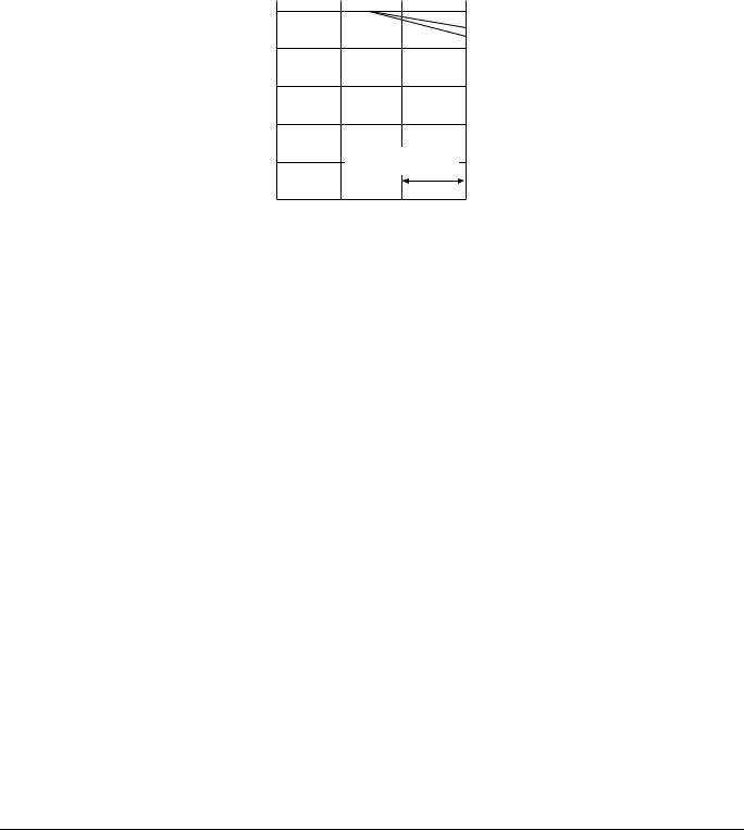
Capacity Tables |
EDUS041011 |
7.3Capacity correction factor by the length of refrigerant piping (Reference)
The cooling and the heating capacity of the unit has to be corrected in accordance with the length of refrigerant piping. (The distance between the indoor unit and the outdoor unit)
<— line : cooling capacity> <--- line : heating capacity>
|
|
R-410A (09/12 class) |
|
|
|
1 |
|
|
|
factor |
|
|
|
|
Capacity correction |
0.9 |
|
|
|
0.8 |
Range of the refrigerant |
|
||
|
additional charge |
|
||
|
|
|
||
|
|
16.4 |
32.8 |
49.2 |
Piping length (ft)
(R11493)
Note:
The graph shows the factor when additional refrigerant of the proper quantity is charged.
18 |
Room Air Conditioners J-Series |
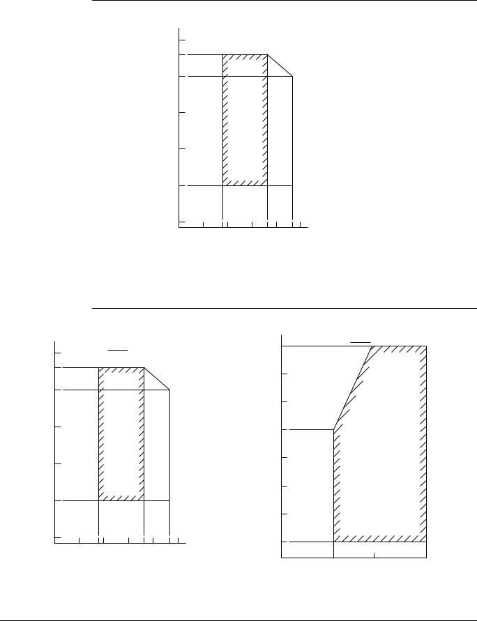
EDUS041011 |
Operation Limit |
8. Operation Limit
RKS09/12JEVJU
|
122 |
|
|
|
|
114.8 |
|
|
|
|
|
|
104 |
|
|
|
|
Outdoor temp. (ûFDB) |
86 |
Continuous operation |
|
|
Pull-down period |
68 |
|
|
|||
|
|
|
|||
|
50 |
|
|
|
|
|
32 |
|
|
|
|
|
50 |
57.2 |
68 |
73.4 |
82.4 86 |
Indoor temp. (ûFWB)
Notes: |
|
The graphs are based |
|
on the following conditions. |
|
¥ Equivalent piping length |
25ft |
¥ Level difference |
0ft |
¥ Air flow rate |
High |
|
|
|
|
|
|
4D066173 |
|
|
RXS09/12JEVJU |
|
|
|
|
|
|
|
|
|
|
|
|
|
|
|
Heating |
|
122 |
|
Cooling |
|
|
|
68 |
|
|
|
|
|
|
|
|
|
|
|
114.8 |
|
|
|
|
|
59 |
|
|
|
|
|
|
|
|
|
|
|
104 |
|
|
|
|
|
|
|
|
|
|
|
|
|
|
50 |
|
|
86 |
|
Continuous operation |
|
Pull-down period |
Outdoor temp. (ûFWB) |
41 |
|
Continuous operation |
|
|
|
|
|||||
68 |
|
|
32 |
|
||||
|
|
|
|
|||||
Outdoor(ûFDB)temp. |
|
|
23 |
|
||||
50 |
|
|
|
|
|
|
|
|
|
|
|
|
|
|
14 |
|
|
32 |
|
|
|
|
|
5 |
|
|
50 |
57.2 |
68 |
73.4 |
82.4 86 |
|
|
|
|
(5ûFDB) |
|
|
||||||
|
|
|
|
|
|
|
||
|
Indoor temp. (ûFWB) |
|
|
50 |
68 |
86 |
||
|
|
|
|
Notes: |
|
|||
|
|
|
|
|
Indoor temp. (ûFDB) |
|
||
|
|
|
|
The graphs are based |
|
|
||
|
|
|
|
|
|
|
|
|
|
|
|
|
on the following conditions. |
|
|
|
|
|
|
|
|
¥ Equivalent piping length |
25ft |
|
|
|
|
|
|
|
¥ Level difference |
0ft |
|
|
3D066174 |
|
|
|
|
¥ Air flow rate |
High |
|
|
|
|
|
|
|
|
|
|
||
Room Air Conditioners J-Series |
19 |
Sound Level |
EDUS041011 |
9. Sound Level
9.1Measuring Location
Indoor Unit
The Single Split Duct-Free System
3.3ft
2.6ft
(R5162)
Outdoor Unit
3.3ft |

 (R4796)
Note:
1.Operation sound is measured in an anechoic chamber.
2.The data are based on the conditions shown in the table below.
Cooling |
Heating |
Piping Length |
|
Indoor ; 80°FDB/67°FWB |
Indoor ; 70°FDB/60°FWB |
25ft |
|
Outdoor ; 95°FDB/75°FWB |
Outdoor ; 47°FDB/43°FWB |
||
|
|||
|
|
|
20 |
Room Air Conditioners J-Series |
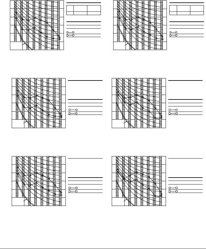
EDUS041011 |
Sound Level |
9.2Octave Band Level
9.2.1Indoor Units
FTKS09JEVJU |
|
|
|
|
|
|
|
|
|
|
|
FTKS12JEVJU |
|
|
|
|
|
|
|
|
|
|
|
||||||
|
|
60 |
|
|
|
|
|
|
|
|
OVER ALL ( dB ) |
|
|
|
60 |
|
|
|
|
|
|
|
|
OVER ALL ( dB ) |
|
||||
|
|
|
|
|
|
|
|
|
|
|
|
|
|
|
|
|
|
|
|
|
|
|
|
||||||
LEVEL |
|
|
|
|
|
NC-50 |
|
|
|
|
60Hz |
|
60Hz |
|
LEVEL |
|
|
|
|
|
NC-50 |
|
|
|
|
60Hz |
|
60Hz |
|
|
50 |
|
|
|
|
|
|
|
SCALE |
208/230V |
208/230V |
|
50 |
|
|
|
|
|
|
|
SCALE |
208/230V |
208/230V |
||||||
|
|
|
|
|
|
|
|
|
|
|
(H) |
|
(L) |
|
|
|
|
|
|
|
|
|
|
|
|
(H) |
|
(L) |
|
SOUNDBANDPRESSURE |
dB(0dB=0.0002 |
|
|
|
|
NC-40 |
|
|
|
A |
40 |
|
26 |
|
SOUNDBANDPRESSURE |
dB(0dB=0.0002 |
|
|
|
|
NC-40 |
|
|
|
A |
41 |
|
27 |
|
40 |
|
|
|
|
|
|
|
|
60Hz 208/230V(L) |
) |
40 |
|
|
|
|
|
|
|
|
60Hz 208/230V(L) |
) |
||||||||
μ bar) |
|
|
|
|
|
|
|
|
OPERATING CONDITIONS |
|
μ bar) |
|
|
|
|
|
|
|
|
OPERATING CONDITIONS |
|
||||||||
|
|
|
|
|
|
NC-30 |
|
|
|
POWER SOURCE |
208/230V 60Hz |
|
|
|
|
|
|
|
NC-30 |
|
|
|
POWER SOURCE |
208/230V 60Hz |
|
||||
|
|
30 |
|
|
|
|
|
|
|
|
JIS STANDARD |
|
|
|
30 |
|
|
|
|
|
|
|
|
JIS STANDARD |
|
||||
|
|
|
|
|
|
|
|
|
|
|
|
|
|
|
|
|
|
|
|
|
|
|
|
||||||
|
|
|
|
|
|
NC-20 |
|
|
|
STANDARD EXTERNAL STATIC PRESSURE |
|
|
|
|
|
|
NC-20 |
|
|
|
STANDARD EXTERNAL STATIC PRESSURE |
||||||||
|
|
|
|
|
|
|
|
|
|
60Hz 208/230V(H) |
|
|
|
|
|
|
|
|
|
|
|
|
60Hz 208/230V(H) |
|
|||||
|
|
20 |
|
|
|
|
|
|
|
|
|
|
|
20 |
|
|
|
|
|
|
|
|
|
||||||
OCTAVE |
|
|
|
|
|
|
|
|
|
|
|
|
|
OCTAVE |
|
|
|
|
|
|
|
|
|
|
|
|
|
||
|
APPROXIMATE |
|
|
|
NC-10 |
|
|
|
|
Cooling |
|
|
|
APPROXIMATE |
|
|
|
NC-10 |
|
|
|
|
Cooling |
|
|
||||
|
|
|
|
|
|
|
|
|
|
|
|
|
|
|
|
|
|
|
|
|
|
|
|
|
|
|
|
||
|
|
10 |
|
|
|
|
|
|
|
|
|
|
|
|
|
|
10 |
|
|
|
|
|
|
|
|
|
|
|
|
|
|
THRESHOLD HEARING |
|
|
|
|
|
|
|
|
|
|
|
|
|
|
THRESHOLD HEARING |
|
|
|
|
|
|
|
|
|
|
|
|
|
|
FOR CONTINUOUS |
|
|
|
|
|
|
|
|
|
|
|
|
|
|
FOR CONTINUOUS |
|
|
|
|
|
|
|
|
|
|
|
|
|
|
NOISE |
|
|
|
|
|
|
|
|
|
|
|
|
|
|
NOISE |
|
|
|
|
|
|
|
|
|
|
|
|
|
|
63 |
125 |
250 |
500 |
1000 |
2000 |
4000 |
8000 |
|
|
|
4D066168 |
|
|
63 |
125 |
250 |
500 |
1000 |
2000 |
4000 |
8000 |
|
|
|
4D066169 |
||
|
|
OCTAVE BAND CENTER FREQUENCY (Hz) |
|
|
|
|
|
|
|
|
|
OCTAVE BAND CENTER FREQUENCY (Hz) |
|
|
|
|
|
|
|||||||||||
FTXS09JEVJU
|
|
COOLING |
|
|
|
|
|
|
|
|
|
60 |
|
|
|
|
|
|
|
LEVEL |
|
50 |
|
|
|
NC-50 |
|
|
|
|
|
|
|
|
|
|
|
||
PRESSURESOUNDBAND |
dB(0dB=0.0002 |
|
|
|
|
NC-40 |
|
|
|
μ bar) |
40 |
|
|
|
|
|
|
|
|
|
|
|
|
|
|
|
|
||
|
|
30 |
|
|
|
NC-30 |
|
|
|
|
|
|
|
|
|
|
|
|
|
|
|
|
|
|
|
NC-20 |
|
|
|
OCTAVE |
|
20 |
|
|
|
|
|
|
|
|
APPROXIMATE |
|
|
|
NC-10 |
|
|
|
|
|
|
10 |
|
|
|
|
|
|
|
|
|
THRESHOLD HEARING |
|
|
|
|
|
|
|
|
|
FOR CONTINUOUS |
|
|
|
|
|
|
|
|
|
NOISE |
|
|
|
|
|
|
|
|
|
63 |
125 |
250 |
500 |
1000 |
2000 |
4000 |
8000 |
|
|
OCTAVE BAND CENTER FREQUENCY (Hz) |
|
||||||
FTXS12JEVJU |
|
|
|
|
|
|
|||
|
|
COOLING |
|
|
|
|
|
|
|
|
|
60 |
|
|
|
|
|
|
|
LEVEL |
|
50 |
|
|
|
NC-50 |
|
|
|
|
|
|
|
|
|
|
|
||
|
|
|
|
|
NC-40 |
|
|
|
|
|
|
|
|
|
|
|
|
|
|
μ bar) |
40 |
|
|
|
|
|
|
|
|
|
|
|
|
|
|
|
|
||
BANDPRESSURESOUND |
dB(0dB=0.0002 |
|
|
|
|
NC-30 |
|
|
|
30 |
|
|
|
|
|
|
|
||
|
|
|
|
NC-20 |
|
|
|
||
20 |
|
|
|
|
|
|
|
||
|
|
|
|
|
|
|
|
||
OCTAVE |
|
|
|
|
|
NC-10 |
|
|
|
|
10 |
|
|
|
|
|
|
|
|
|
APPROXIMATE |
|
|
|
|
|
|
|
|
|
|
THRESHOLD HEARING |
|
|
|
|
|
|
|
|
|
FOR CONTINUOUS |
|
|
|
|
|
|
|
|
|
NOISE |
|
|
|
|
|
|
|
|
|
63 |
125 |
250 |
500 |
1000 |
2000 |
4000 |
8000 |
|
|
OCTAVE BAND CENTER FREQUENCY (Hz) |
|
||||||
OVER ALL ( dB )
|
60Hz |
60Hz |
SCALE |
208/230V |
208/230V |
|
(H) |
(L) |
A |
40 |
26 |
( B.G.N IS ALREADY RECTIFIED )
OPERATING CONDITIONS
POWER SOURCE 208/230V 60Hz
JIS STANDARD
STANDARD EXTERNAL STATIC PRESSURE 60Hz 208/230V(H)
60Hz 208/230V(L)
Cooling
OVER ALL ( dB )
|
60Hz |
60Hz |
SCALE |
208/230V |
208/230V |
|
(H) |
(L) |
A |
41 |
27 |
( B.G.N IS ALREADY RECTIFIED )
OPERATING CONDITIONS
POWER SOURCE 208/230V 60Hz
JIS STANDARD
STANDARD EXTERNAL STATIC PRESSURE 60Hz 208/230V(H)
60Hz 208/230V(L)
Cooling
|
|
HEATING |
|
|
|
|
|
|
|
|
|
60 |
|
|
|
|
|
|
|
LEVEL |
|
50 |
|
|
|
NC-50 |
|
|
|
|
|
|
|
|
|
|
|
||
PRESSURESOUNDBAND |
dB(0dB=0.0002 |
|
|
|
|
NC-40 |
|
|
|
40 |
|
|
|
|
|
|
|
||
μ bar) |
|
|
|
|
|
|
|
||
|
|
|
|
|
|
|
|
||
|
|
|
|
|
|
NC-30 |
|
|
|
|
|
30 |
|
|
|
|
|
|
|
|
|
20 |
|
|
|
NC-20 |
|
|
|
OCTAVE |
|
|
|
|
|
|
|
|
|
|
APPROXIMATE |
|
|
|
NC-10 |
|
|
|
|
|
|
10 |
|
|
|
|
|
|
|
|
|
THRESHOLD HEARING |
|
|
|
|
|
|
|
|
|
FOR CONTINUOUS |
|
|
|
|
|
|
|
|
|
NOISE |
|
|
|
|
|
|
|
|
|
63 |
125 |
250 |
500 |
1000 |
2000 |
4000 |
8000 |
|
|
|
OCTAVE BAND CENTER FREQUENCY (Hz) |
|
|||||
|
|
HEATING |
|
|
|
|
|
|
|
|
|
60 |
|
|
|
|
|
|
|
LEVEL |
|
50 |
|
|
|
NC-50 |
|
|
|
|
|
|
|
|
|
|
|
||
|
|
|
|
|
NC-40 |
|
|
|
|
|
|
|
|
|
|
|
|
|
|
μ bar) |
40 |
|
|
|
|
|
|
|
|
|
|
|
|
|
|
|
|
||
BANDPRESSURESOUND |
dB(0dB=0.0002 |
30 |
|
|
|
NC-30 |
|
|
|
|
|
|
|
|
|
|
|||
|
|
|
|
NC-20 |
|
|
|
||
20 |
|
|
|
|
|
|
|
||
|
|
|
|
|
|
|
|
||
OCTAVE |
|
10 |
|
|
|
NC-10 |
|
|
|
|
|
|
|
|
|
|
|
||
|
APPROXIMATE |
|
|
|
|
|
|
|
|
|
|
THRESHOLD HEARING |
|
|
|
|
|
|
|
|
|
FOR CONTINUOUS |
|
|
|
|
|
|
|
|
|
NOISE |
|
|
|
|
|
|
|
|
|
63 |
125 |
250 |
500 |
1000 |
2000 |
4000 |
8000 |
|
|
|
OCTAVE BAND CENTER FREQUENCY (Hz) |
|
|||||
OVER ALL ( dB )
SCALE |
60Hz |
60Hz |
208/230V |
208/230V |
|
|
(H) |
(L) |
A |
40 |
28 |
( B.G.N IS ALREADY RECTIFIED )
OPERATING CONDITIONS
POWER SOURCE 208/230V 60Hz
JIS STANDARD
STANDARD EXTERNAL STATIC PRESSURE 60Hz 208/230V(H)
60Hz 208/230V(L)
Heating
3D066170
OVER ALL ( dB )
SCALE |
60Hz |
60Hz |
208/230V |
208/230V |
|
|
(H) |
(L) |
A |
41 |
29 |
|
|
|
( B.G.N IS ALREADY RECTIFIED )
OPERATING CONDITIONS
POWER SOURCE 208/230V 60Hz
JIS STANDARD
STANDARD EXTERNAL STATIC PRESSURE 60Hz 208/230V(H)
60Hz 208/230V(L)
Heating
3D066171
Room Air Conditioners J-Series |
21 |

Sound Level |
EDUS041011 |
9.2.2Outdoor Units
RKS09JEVJU |
|
|
|
|
|
|
|
|
|
RKS12JEVJU |
|
|
|
|
|
|
|
|
|
|||||||
|
70 |
|
|
|
|
|
|
OVER ALL ( dB ) |
|
|
|
|
|
70 |
|
|
|
|
|
|
|
OVER ALL ( dB ) |
|
|||
|
|
|
|
|
|
|
|
|
|
|
|
|
|
|
|
|
|
|
|
|
|
|
||||
LEVEL |
60 |
|
|
|
NC-60 |
|
|
SCALE |
60Hz |
|
|
LEVEL |
|
|
60 |
|
|
|
NC-60 |
|
|
SCALE |
60Hz |
|
||
|
|
|
|
|
|
|
208/230V(H) |
|
|
|
|
|
|
|
|
|
|
|
208/230V(H) |
|||||||
|
|
|
|
|
|
|
|
|
|
|
|
|
|
|
|
|
|
|
|
|
|
|
||||
PRESSURESOUNDBAND dB(0dB=0.0002 |
|
|
|
|
|
NC-50 |
|
|
A |
48 |
|
|
PRESSURESOUNDBAND |
dB(0dB=0.0002 |
|
|
|
|
NC-50 |
|
|
A |
48 |
|
||
50 |
|
|
|
|
|
|
( B.G.N IS ALREADY RECTIFIED ) |
50 |
|
|
|
|
|
|
|
( B.G.N IS ALREADY RECTIFIED ) |
||||||||||
μ bar) |
|
|
|
|
|
|
μ bar) |
|
|
|
|
|
|
|
||||||||||||
|
|
|
|
|
NC-40 |
|
|
OPERATING CONDITIONS |
|
|
|
|
NC-40 |
|
|
OPERATING CONDITIONS |
||||||||||
|
|
|
|
|
|
|
|
POWER SOURCE |
208/230V 60Hz |
|
|
|
|
|
|
|
|
|
POWER SOURCE |
208/230V 60Hz |
||||||
|
40 |
|
|
|
|
|
|
|
|
|
40 |
|
|
|
|
|
|
|
||||||||
|
|
|
|
|
|
|
JIS STANDARD |
|
|
|
|
|
|
|
|
|
|
|
|
JIS STANDARD |
|
|||||
|
|
|
|
|
|
|
|
|
|
|
|
|
|
|
|
|
|
|
|
|
|
|
||||
|
|
|
|
|
|
NC-30 |
|
|
|
60Hz |
208/230V |
|
|
|
|
|
|
|
NC-30 |
|
|
|
60Hz |
208/230V |
||
|
30 |
|
|
|
|
|
|
Cooling |
|
|
|
|
|
30 |
|
|
|
|
|
|
Cooling |
|
||||
OCTAVE |
|
|
|
|
|
|
|
|
|
OCTAVE |
|
|
|
|
|
|
|
|
|
|
|
|||||
|
APPROXIMATE |
|
|
|
NC-20 |
|
|
|
|
|
|
|
|
APPROXIMATE |
|
|
|
NC-20 |
|
|
|
|
|
|||
|
|
|
|
|
|
|
|
|
|
|
|
|
|
|
|
|
|
|
|
|
|
|
|
|||
|
20 |
|
|
|
|
|
|
|
|
|
|
|
|
|
20 |
|
|
|
|
|
|
|
|
|
|
|
|
|
THRESHOLD HEARING |
|
|
|
|
|
|
|
|
|
|
|
|
|
THRESHOLD HEARING |
|
|
|
|
|
|
|
|
|
|
|
|
FOR CONTINUOUS |
|
|
|
|
|
|
|
|
|
|
|
|
|
FOR CONTINUOUS |
|
|
|
|
|
|
|
|
|
|
|
|
NOISE |
|
|
|
|
|
|
|
|
|
|
|
|
|
NOISE |
|
|
|
|
|
|
|
|
|
|
|
|
63 |
125 |
250 |
500 |
1000 |
2000 |
4000 |
8000 |
4D066163 |
|
|
|
63 |
125 |
250 |
500 |
1000 |
2000 |
4000 |
8000 |
|
4D066164 |
|||
|
|
OCTAVE BAND CENTER FREQUENCY (Hz) |
|
|
|
|
|
|
|
|
OCTAVE BAND CENTER FREQUENCY (Hz) |
|
|
|
|
|||||||||||
RXS09JEVJU |
|
|
|
|
|
|
|
|
|
|
|
|
|
|
|
|
|
|
|
|
|
|
|
|||
|
|
COOLING |
|
|
|
|
|
|
|
|
|
|
|
|
HEATING |
|
|
|
|
|
|
|
|
|
||
|
|
70 |
|
|
|
|
|
|
OVER ALL ( dB ) |
|
|
|
|
70 |
|
|
|
|
|
|
|
OVER ALL ( dB ) |
|
|||
|
|
|
|
|
|
|
|
|
|
|
|
|
|
|
|
|
|
|
|
|
|
|
||||
LEVEL |
|
60 |
|
|
|
NC-60 |
|
SCALE |
60Hz |
|
|
LEVEL |
|
60 |
|
|
|
NC-60 |
|
|
|
SCALE |
60Hz |
|
||
|
|
|
|
|
|
|
208/230V(H) |
|
|
|
|
|
|
|
|
208/230V(H) |
||||||||||
|
|
|
|
|
|
|
|
|
|
|
|
|
|
|
|
|
|
|
|
|
|
|||||
PRESSURESOUNDBAND |
dB(0dB=0.0002 |
|
|
|
|
NC-50 |
|
A |
48 |
|
|
PRESSURESOUNDBAND dB(0dB=0.0002 |
|
|
|
|
|
NC-50 |
|
|
|
A |
48 |
|
||
50 |
|
|
|
|
|
|
( B.G.N IS ALREADY RECTIFIED ) |
50 |
|
|
|
|
|
|
|
( B.G.N IS ALREADY RECTIFIED ) |
||||||||||
μ bar) |
|
|
|
|
|
|
μ bar) |
|
|
|
|
|
|
|
||||||||||||
|
|
|
|
NC-40 |
|
OPERATING CONDITIONS |
|
|
|
|
|
NC-40 |
|
|
|
OPERATING CONDITIONS |
||||||||||
|
|
|
|
|
|
|
POWER SOURCE |
208/230V 60Hz |
|
|
|
|
|
|
|
|
|
|
POWER SOURCE |
208/230V 60Hz |
||||||
|
|
40 |
|
|
|
|
|
|
|
|
40 |
|
|
|
|
|
|
|
||||||||
|
|
|
|
|
|
|
|
JIS STANDARD |
|
|
|
|
|
|
|
|
|
|
|
JIS STANDARD |
|
|||||
|
|
|
|
|
|
|
|
|
|
|
|
|
|
|
|
|
|
|
|
|
|
|
||||
|
|
|
|
|
|
NC-30 |
|
|
60Hz |
208/230V |
|
|
|
|
|
|
|
NC-30 |
|
|
|
|
60Hz |
208/230V |
||
|
|
30 |
|
|
|
|
|
Cooling |
|
|
|
|
30 |
|
|
|
|
|
|
|
Heating |
|
||||
OCTAVE |
|
|
|
|
|
|
|
|
|
|
OCTAVE |
|
|
|
|
|
|
|
|
|
|
|||||
|
APPROXIMATE |
|
|
|
NC-20 |
|
|
|
|
|
|
|
APPROXIMATE |
|
|
|
NC-20 |
|
|
|
|
|
|
|||
|
|
20 |
|
|
|
|
|
|
|
|
|
|
|
|
20 |
|
|
|
|
|
|
|
|
|
|
|
|
|
THRESHOLD HEARING |
|
|
|
|
|
|
|
|
|
|
|
|
THRESHOLD HEARING |
|
|
|
|
|
|
|
|
|
||
|
|
FOR CONTINUOUS |
|
|
|
|
|
|
|
|
|
|
|
|
|
FOR CONTINUOUS |
|
|
|
|
|
|
|
|
|
|
|
|
NOISE |
|
|
|
|
|
|
|
|
|
|
|
|
|
NOISE |
|
|
|
|
|
|
|
|
|
|
|
|
63 |
125 |
250 |
500 |
1000 |
2000 |
4000 |
8000 |
|
|
|
|
|
|
63 |
125 |
250 |
500 |
1000 |
2000 |
4000 |
8000 |
|
3D066166 |
|
|
|
OCTAVE BAND CENTER FREQUENCY (Hz) |
|
|
|
|
|
|
|
OCTAVE BAND CENTER FREQUENCY (Hz) |
|
|
|
|
||||||||||||
RXS12JEVJU |
|
|
|
|
|
|
|
|
|
|
|
|
|
|
|
|
|
|
|
|
|
|
|
|||
|
|
COOLING |
|
|
|
|
|
|
|
|
|
|
|
|
HEATING |
|
|
|
|
|
|
|
|
|
||
|
|
70 |
|
|
|
|
|
|
OVER ALL ( dB ) |
|
|
|
|
70 |
|
|
|
|
|
|
|
OVER ALL ( dB ) |
|
|||
|
|
|
|
|
|
|
|
|
|
|
|
|
|
|
|
|
|
|
|
|
|
|
||||
LEVEL |
|
60 |
|
|
|
NC-60 |
|
SCALE |
60Hz |
|
|
LEVEL |
|
60 |
|
|
|
NC-60 |
|
|
|
SCALE |
60Hz |
|
||
|
|
|
|
|
|
|
208/230V(H) |
|
|
|
|
|
|
|
|
208/230V(H) |
||||||||||
|
|
|
|
|
|
|
|
|
|
|
|
|
|
|
|
|
||||||||||
|
|
|
|
|
|
|
|
|
|
|
|
|
|
|
|
|
|
|
|
|
|
|||||
PRESSURESOUNDBAND |
dB(0dB=0.0002 |
|
|
|
|
NC-50 |
|
A |
48 |
|
|
PRESSURESOUNDBAND dB(0dB=0.0002 |
|
|
|
|
|
NC-50 |
|
|
|
A |
49 |
|
||
50 |
|
|
|
|
|
|
( B.G.N IS ALREADY RECTIFIED ) |
50 |
|
|
|
|
|
|
|
( B.G.N IS ALREADY RECTIFIED ) |
||||||||||
μ bar) |
|
|
|
|
|
|
μ bar) |
|
|
|
|
|
|
|
||||||||||||
|
|
|
|
NC-40 |
|
OPERATING CONDITIONS |
|
|
|
|
|
NC-40 |
|
|
|
OPERATING CONDITIONS |
||||||||||
|
|
|
|
|
|
|
POWER SOURCE |
208/230V 60Hz |
|
|
|
|
|
|
|
|
|
|
POWER SOURCE |
208/230V 60Hz |
||||||
|
|
40 |
|
|
|
|
|
|
|
|
40 |
|
|
|
|
|
|
|
||||||||
|
|
|
|
|
|
|
|
JIS STANDARD |
|
|
|
|
|
|
|
|
|
|
|
JIS STANDARD |
|
|||||
|
|
|
|
|
|
|
|
|
|
|
|
|
|
|
|
|
|
|
|
|
|
|
||||
|
|
|
|
|
|
NC-30 |
|
|
60Hz |
208/230V |
|
|
|
|
|
|
|
NC-30 |
|
|
|
|
60Hz |
208/230V |
||
|
|
30 |
|
|
|
|
|
Cooling |
|
|
|
|
30 |
|
|
|
|
|
|
|
Heating |
|
||||
OCTAVE |
|
|
|
|
|
|
|
|
|
|
OCTAVE |
|
|
|
|
|
|
|
|
|
|
|||||
|
APPROXIMATE |
|
|
|
NC-20 |
|
|
|
|
|
|
|
APPROXIMATE |
|
|
|
NC-20 |
|
|
|
|
|
|
|||
|
|
20 |
|
|
|
|
|
|
|
|
|
|
|
|
20 |
|
|
|
|
|
|
|
|
|
|
|
|
|
THRESHOLD HEARING |
|
|
|
|
|
|
|
|
|
|
|
|
THRESHOLD HEARING |
|
|
|
|
|
|
|
|
|
||
|
|
FOR CONTINUOUS |
|
|
|
|
|
|
|
|
|
|
|
|
|
FOR CONTINUOUS |
|
|
|
|
|
|
|
|
|
|
|
|
NOISE |
|
|
|
|
|
|
|
|
|
|
|
|
|
NOISE |
|
|
|
|
|
|
|
|
|
|
|
|
63 |
125 |
250 |
500 |
1000 |
2000 |
4000 |
8000 |
|
|
|
|
|
|
63 |
125 |
250 |
500 |
1000 |
2000 |
4000 |
8000 |
|
3D066167 |
|
|
|
OCTAVE BAND CENTER FREQUENCY (Hz) |
|
|
|
|
|
|
|
OCTAVE BAND CENTER FREQUENCY (Hz) |
|
|
|
|
||||||||||||
22 |
Room Air Conditioners J-Series |

EDUS041011 Electric Characteristics
10. Electric Characteristics
Representative Unit Combination |
|
Power Supply |
|
|
COMP |
|
OFM |
|
IFM |
|||
|
|
|
|
|
|
|
|
|
|
|
|
|
Indoor Unit |
Outdoor Unit |
Hz-Volts |
Voltage Range |
MCA |
MOP |
RLA |
W |
|
FLA |
W |
|
FLA |
|
|
|
|
|
|
|
|
|
|
|
|
|
FTKS09JEVJU |
RKS09JEVJU |
60-208 |
MAX. 60Hz 253V |
4.4 |
15 |
3.7 |
33 |
|
0.19 |
40 |
|
0.20 |
60-230 |
MIN. 60Hz 187V |
3.4 |
|
0.17 |
|
0.18 |
||||||
|
|
|
|
|
|
|
|
|||||
|
|
|
|
|
|
|
|
|
|
|
|
|
FTKS12JEVJU |
RKS12JEVJU |
60-208 |
MAX. 60Hz 253V |
4.4 |
15 |
3.7 |
33 |
|
0.19 |
40 |
|
0.20 |
60-230 |
MIN. 60Hz 187V |
3.4 |
|
0.17 |
|
0.18 |
||||||
|
|
|
|
|
|
|
|
|||||
|
|
|
|
|
|
|
|
|
|
|
|
|
FTXS09JEVJU |
RXS09JEVJU |
60-208 |
MAX. 60Hz 253V |
4.3 |
15 |
3.7 |
33 |
|
0.19 |
40 |
|
0.20 |
60-230 |
MIN. 60Hz 187V |
3.3 |
|
0.17 |
|
0.18 |
||||||
|
|
|
|
|
|
|
|
|||||
|
|
|
|
|
|
|
|
|
|
|
|
|
FTXS12JEVJU |
RXS12JEVJU |
60-208 |
MAX. 60Hz 253V |
5.2 |
15 |
4.4 |
33 |
|
0.19 |
40 |
|
0.20 |
60-230 |
MIN. 60Hz 187V |
4.0 |
|
0.17 |
|
0.18 |
||||||
|
|
|
|
|
|
|
|
|||||
|
|
|
|
|
|
|
|
|
|
|
|
|
Symbols:
MCA |
: MIN. CIRCUIT AMPS (A) |
MOP |
: MAX OVERCURRENT PROTECTION |
RLA |
: RATED LOAD AMPS (A) |
OFM |
: OUTDOOR FAN MOTOR |
IFM |
: INDOOR FAN MOTOR |
FLA |
: FULL LOAD AMPS (A) |
W |
: FAN MOTOR RATED OUTPUT (W) |
Note:
1.Maximum allowable voltage variation between phases is 2%.
2.Select wire size based on the larger value of MCA.
3.Instead of fuse, use circuit breaker.
4.Be sure to install a ground leak detector. (One that can handle higher harmonics.)
(This unit uses an inverter, which means that it must use a ground leak detector capable handling high harmonics in order to prevent malfunctioning of the ground leak detector itself.)
3D066179B
Room Air Conditioners J-Series |
23 |
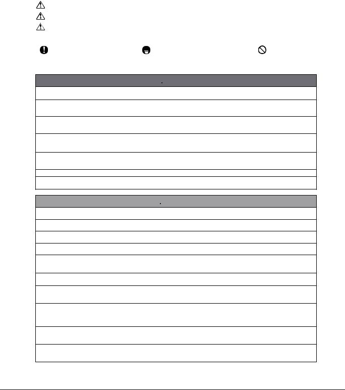
Installation Manual |
EDUS041011 |
11. Installation Manual
11.1Indoor Units
Safety Precautions
¥Read these Safety Precautions carefully to ensure correct installation.
¥This manual classifies the precautions into DANGER, WARNING and CAUTION. Be sure to follow all the precautions below: they are all important for ensuring safety.
DANGER .......... |
Indicates an imminently hazardous situation which, if not avoided, will result in death or serious injury. |
||
WARNING ........ |
Failure to follow any of WARNING is likely to result in such grave consequences as death or serious injury. |
||
CAUTION ......... |
Failure to follow any of CAUTION may in some cases result in grave consequences. |
||
¥ The following safety symbols are used throughout this manual: |
|
||
|
|
|
|
Be sure to observe this instruction. |
Be sure to establish a ground connection. |
Never attempt. |
|
|
|
|
|
¥After completing installation, test the unit to check for installation errors. Give the user adequate instructions concerning the use and cleaning of the unit according to the Operation Manual.
 DANGER
¥Refrigerant gas is heavier than air and replaces oxygen. A massive leak could lead to oxygen depletion, especially in basements, and an asphyxiation hazard could occur leading to serious injury or death.
¥If the refrigerant gas leaks during installation, ventilate the area immediately.
Refrigerant gas may produce a toxic gas if it comes in contact with fire such as from a fan heater, stove or cooking device. Exposure to this gas could cause severe injury or death.
¥ After completing the installation work, check that the refrigerant gas does not leak.
Refrigerant gas may produce a toxic gas if it comes in contact with fire such as from a fan heater, stove or cooking device. Exposure to this gas could cause severe injury or death.
¥Do not ground units to water pipes, telephone wires or lightning rods because incomplete grounding could cause a severe shock hazard resulting in severe injury or death, and to gas pipes because a gas leak could result in an explosion which could lead to severe injury or death.
¥Safely dispose of the packing materials.
Packing materials, such as nails and other metal or wooden parts, may cause stabs or other injuries. Tear apart and throw away plastic packaging bags so that children will not play with them. Children playing with plastic bags face the danger of death by suffocation.
¥Do not install unit in an area where flammable materials are present due to risk of explosion resulting in serious injury or death.
¥Do not ground units to telephone wires or lightning rods because lightning strikes could cause a severe shock hazard resulting in severe injury or death, and to gas pipes because a gas leak could result in an explosion which could lead to severe injury or death.
 WARNING
¥ Installation should be left to the authorized dealer or another trained professional.
Improper installation may cause water leakage, electrical shock, fire, or equipment damage.
¥ Install the air conditioner according to the instructions given in this manual.
Incomplete installation may cause water leakage, electrical shock, fire or equipment damage.
¥ Be sure to use the supplied or exact specified installation parts.
Use of other parts may cause the unit to come to fall, water leakage, electrical shock, fire or equipment damage.
¥ Install the air conditioner on a solid base that is level and can support the weight of the unit.
An inadequate base or incomplete installation may cause injury or equipment damage in the event the unit falls off the base or comes loose.
¥ Electrical work should be carried out in accordance with the installation manual and the national, state and local electrical wiring codes.
Insufficient capacity or incomplete electrical work may cause electrical shock, fire or equipment damage.
¥Be sure to use a dedicated power circuit. Never use a power supply shared by another appliance. Follow all appropriate electrical codes.
¥For wiring, use a wire or cable long enough to cover the entire distance with no splices if possible. Do not use an
extension cord. Do not put other loads on the power supply. Use an only a separate dedicated power circuit.
(Failure to do so may cause abnormal heat, electric shock, fire or equipment damage.)
¥ Use the specified types of wires for electrical connections between the indoor and outdoor units. Follow all state and local electrical codes.
Firmly clamp the inter-unit wiring so their terminals receive no external stresses. Incomplete connections or clamping may cause terminal overheating, fire or equipment damage.
¥ After connecting all wiring be sure to shape the cables so that they do not put undue stress on the electrical covers, panels or terminals.
Install covers over the wires. Incomplete cover installation may cause terminal overheating, electrical shock,fire or equipment damage.
¥ When installing or relocating the system, be sure to keep the refrigerant circuit free from all substances other than the specified refrigerant (R410A), such as air.
(Any presence of air or other foreign substance in the refrigerant circuit causes an abnormal pressure rise which may result in rupture, resulting in injury.)
1
24 |
Room Air Conditioners J-Series |
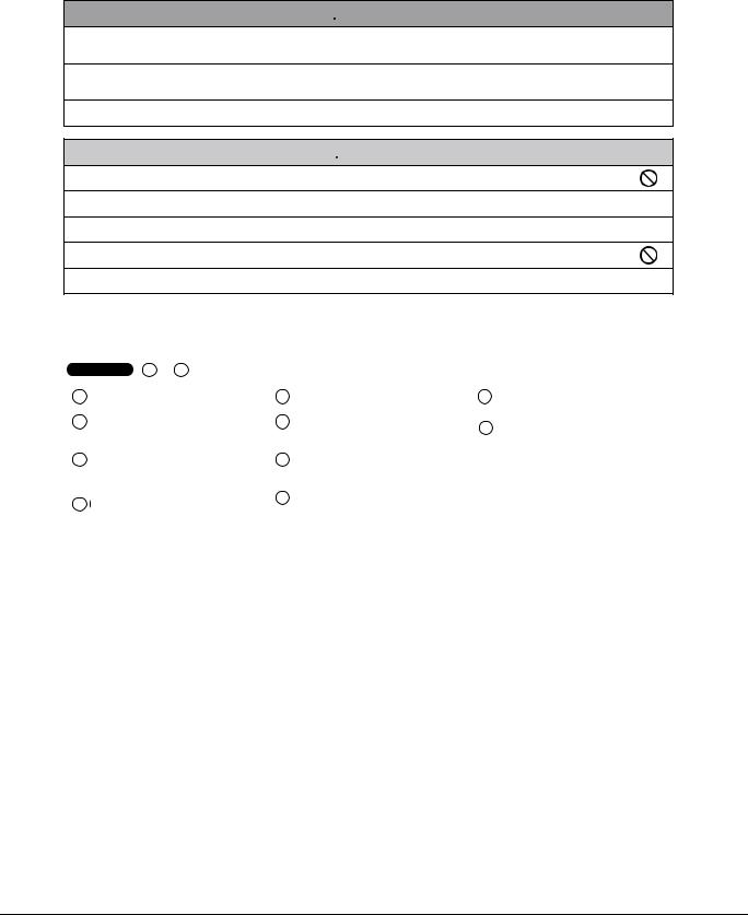
EDUS041011 |
Installation Manual |
Safety Precautions
 WARNING
¥ During pump-down, stop the compressor before removing the refrigerant piping.
If the compressor is still running and the stop valve is open during pump-down, air will be sucked in when the refrigerant piping is removed, causing abnormally high pressure which could lead to equipment damage or and personal injury.
¥ During installation, attach the refrigerant piping securely before running the compressor.
If the compressor is not attached and the stop valve is open during pump-down, air will be sucked in when the compressor is run, causing abnormally high pressure which could lead to equipment damage and personal injury.
¥ Be sure to install a ground fault circuit interrupter breaker.
Failure to install a ground fault circuit interrupter breaker may result in electrically shocks, or fire personal injury.
 CAUTION
¥ Do not install the air conditioner where gas leakage would be exposed to open flames.
If the gas leaks and builds up around the unit, it may catch fire.
¥ Establish drain piping according to the instructions of this manual.
Inadequate piping may cause water damage.
¥ Tighten the flare nut according to the specified torque. A torque wrench should be used.
If the flare nut is tightened too much, the flare nut may crack over time and cause refrigerant leakage.
¥ Do not touch the heat exchanger fins.
Improper handling may result in injury.
¥ Be very careful about product transportation.
Some products use PP bands for packaging. Do not use any PP bands for a means of transportation. It is dangerous.
Accessories
Indoor unit |
A Ð K , |
|
|
|
|
|
|
|
|
|
|
|
|
|
|
|
|
A Mounting plate |
1 |
E |
Remote controller holder |
1 |
J |
Operation manual |
1 |
|
|
|
|
|
|
|
|
|
|
B Mounting plate fixing screw |
6 |
F |
Fixing screw for remote controller |
2 |
K |
Installation manual |
1 |
|
3/16Ó × 1Ó (M4 × 25mm) |
|
holder 1/8Ó × 13/16Ó (M3 × 20mm) |
||||||
|
|
|
|
|
|
|||
|
|
|
|
|
|
|
|
|
C Titanium apatite photocatalytic |
2 |
G |
Dry battery AAA. LR03 |
2 |
|
|
|
|
air-purifying filter |
|
(alkaline) |
|
|
|
|||
|
|
|
|
|
|
|||
|
|
|
|
|
|
|
|
|
D Wireless remote controller |
1 |
H |
Indoor unit fixing screw |
2 |
|
|
|
|
|
3/16Ó × 1/2Ó (M4 × 12mm) |
|
|
|
||||
|
|
|
|
|
|
|
|
|
|
|
|
|
|
|
|
|
|
Choosing an Installation Site
¥ Before choosing the installation site, obtain user approval.
1. Indoor unit
¥The indoor unit should be sited in a place where:
1)the restrictions on installation specified in the indoor unit installation drawings are met,
2)both air inlet and air outlet have clear paths met,
3)the unit is not in the path of direct sunlight,
4)the unit is away from the source of heat or steam,
5)there is no source of machine oil vapour (this may shorten indoor unit life),
6)cool (warm) air is circulated throughout the room,
7)the unit is away from electronic ignition type fluorescent lamps (inverter or rapid start type) as they may shorten the remote controller range,
8)the unit is at least 3.5 feet (1m) away from any television or radio set (unit may cause interference with the picture or sound).
2.Wireless remote controller
1)Turn on all the fluorescent lamps in the room, if any, and find the site where remote control signals are properly received by the indoor unit (within 23 feet (7m)).
2
Room Air Conditioners J-Series |
25 |

Installation Manual |
EDUS041011 |
Preparation before Installation
1. Removing and installing front panel
•Removal method
Hook fingers on the tabs on the left and right of the main body, and open until the panel stops. Slide the front panel sideways to disengage the rotating shaft. Then pull the front panel toward you to remove it.
•Installation method
Align the tabs of the front panel with the grooves, and push all the way in. Then close slowly. Push the center of the lower surface of the panel firmly to engage the tabs.
2.Removing and installing front grille
•Removal method
1)Remove front panel to remove the air filter.
2)Remove 2 screws from the front grille.
3)In front of the mark of the front grille, there are 3 upper hooks. Lightly pull the front grille toward you with one hand, and push down on the hooks with the fingers of your other hand.
Push the rotating shaft of the front panel into the groove.
Upper hook
mark area (3 locations)
 Upper hook Push
down.
Lightly pull the front grille toward you with one hand, and push down on the hooks with the fingers of your other hand. (3 locations)
When there is no work space because the unit is close to ceiling
 CAUTION
¥ Be sure to wear protection gloves.
Place both hands under the center of the front grille, and while pushing up, pull it toward you.
• Installation method
1)Install the front grille and firmly engage the upper hooks (3 locations).
2)Install 2 screws of the front grille.
3)Install the air filter and then mount the front panel.
1) Push up.
2) Pull toward you.
3. How to set the different addresses
When two indoor units are installed in one room, the two wireless remote controllers can be set for different addresses.
1)In the same way as when connecting to an HA system, remove the metal plate electrical wiring cover.
2)Cut the address jumper (JA) on the printed circuit board.
3)Cut the address jumper (J4) in the remote controller.
JA
|
|
|
|
|
|
|
|
|
|
|
|
|
|
|
|
|
|
|
|
|
|
|
|
|
|
|
|
|
|
|
|
|
|
|
|
|
|
|
|
|
|
|
|
|
|
JA |
ADDRESS |
|
|
|
|
|
|
|
|
|
|
EXIST |
1 |
|
|
|
|
|
|
|
|
|
|
||
|
|
|
|
|
|
|
|
|
|
CUT |
2 |
J4
J4 |
ADDRESS |
EXIST |
1 |
CUT |
2 |
3
26 |
Room Air Conditioners J-Series |
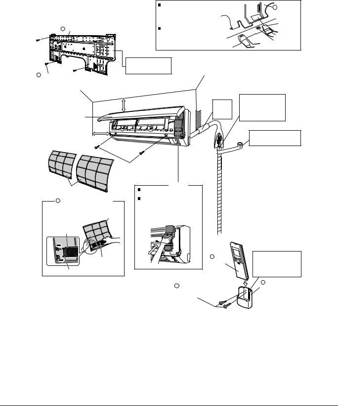
EDUS041011 |
Installation Manual |
Indoor Unit Installation Drawings
A Mounting plate
B Mounting plate fixing screw 3/16Ó × 1Ó (M4 × 25mm)
Front panel
1-15/16Ó (50mm) or more from walls (on both sides)
How to attach the indoor unit |
|
A Mounting |
|
Hook the claws of the bottom frame |
|
||
|
plate |
||
to the mounting plate. |
|
||
|
|
||
If the claws are difficult to hook, |
|
|
|
remove the front grille. |
|
Clip |
|
|
|
||
How to remove the indoor unit |
|
|
|
Push up the marked area (at the |
|
|
|
lower part of the front grille) to |
Bottom frame |
Mark (rear side) |
|
release the claws. If it is difficult to Front grille |
|||
|
|||
release, remove the front grille. |
|
|
The mounting plate should be installed on a wall which can support the weight of the indoor unit.
1-3/16Ó (30mm) or more |
|
Cut thermal insulation |
|
Caulk |
pipe to an appropriate |
||
from ceiling |
length and wrap it with |
||
pipe hole |
|||
|
tape, making sure that no |
||
|
gap |
||
|
gap is left in the insulation |
||
|
with putty. |
||
|
pipeÕs cut line. |
||
|
|
||
|
|
Wrap the insulation pipe with |
|
|
|
the finishing tape from bottom |
|
|
|
to top. |
|
3/16Ó × 5/8Ó |
|
|
|
(M4 × 16mm) |
|
|
|
Service lid |
|
Air filters |
Opening service lid |
|
|
Service lid is opening/closing type. |
|
C Titanium apatite photocatalytic |
Opening method |
|
1) Remove the service lid screws. |
||
air-purifying filter (2) |
||
2) Pull out the service lid diagonally |
||
|
||
|
down in the direction of the arrow. |
|
Air filter |
3) Pull down. |
|
Filter frame |
|
|
Titanium apatite |
D |
|
Wireless |
||
photocatalytic |
||
remote |
||
air-purifying filter |
||
controller |
||
Tab |
||
|
F Fixing screw for remote |
|
|
controller holder |
|
|
1/8Ó × 13/16Ó (M3 × 20mm) |
Before screwing the remote controller holder to the wall, make sure that control signals are properly received by indoor unit.
E Remote
controller holder
4
Room Air Conditioners J-Series |
27 |
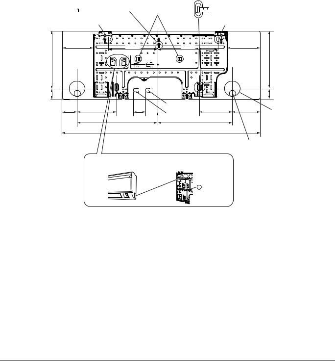
Installation Manual |
EDUS041011 |
Indoor Unit Installation
1. Installing the mounting plate
¥The mounting plate should be installed on a wall which can support the weight of the indoor unit.
1)Temporarily secure the mounting plate to the wall, make sure that the plate is completely level, and mark the boring points on the wall.
2)Secure the mounting plate to the wall with screws.
Recommended mounting plate retention spots and dimensions
Recommended mounting plate |
Place a leveler |
||||||||||||
retention spots (5 spots in all) |
on raised tab. |
||||||||||||
(Bolt size: 3/8 (M10)) |
|
||||||||||||
|
|
|
|
|
|
|
|
|
|
|
|
|
|
|
|
|
|
|
|
|
|
|
|
|
|
|
|
Use tape measure as shown. Position the end of a tape measure at  .
.
(Bolt size: 3/8 (M10))
|
4-47/64 |
|
7-63/64 |
9-23/32 |
|
4-31/32 |
|
|
(120.5) |
|
|
(101) |
|
||
|
|
(203) |
(247) |
|
|
||
9-33/64 |
(241.7) |
|
|
9-33/64 |
(241.7) |
||
|
|
|
|
||||
1-5/8 |
(41.3) |
|
|
|
|
1-5/8 |
(41.3) |
|
|
|
|
Gas pipe end |
|
|
|
|
2-9/64 |
6-19/64 |
1-31/32 |
Liquid pipe end |
6-19/64 |
2-1/8 |
Through- |
|
(54.5) |
(160) |
(50) |
(160) |
(54) |
the-wall hole |
|
|
|
|
13-1/64 |
13-1/32 |
|
|
φ2-9/16 (φ65) |
|
|
|
|
|
|
||
|
|
|
(330.5) |
(331) |
|
|
|
|
|
|
|
30-5/16 |
|
|
|
|
|
|
|
(770) |
|
|
|
|
|
|
|
|
|
Drain hose |
unit: inch (mm) |
|
|
|
|
|
|
position |
|
* The removed pipe port cover can be |
Removed pipe |
||||
kept in the mounting plate pocket. |
|||||
port cover |
|||||
|
|||||
|
|
|
|
|
|
|
|
|
|
|
|
A Mounting plate
5
28 |
Room Air Conditioners J-Series |
 Loading...