


C AM IP10
W IRELES S IP COL OUR CAMERA DRAADLOZE IP K LEUREN CAMERA C AMÉRA C OULEU R IP SAN S FIL
C ÁMARA I P INAL ÁMBRIC A A COL OR DRAHTLOSE IP-F ARBKAMERA
U SER MAN UAL |
3 |
G EBRUIKE RSHANDLEIDING |
18 |
N OTICE D’EMPLOI |
34 |
M ANUAL D EL USUA RIO |
50 |
BEDIENUN GSANLEITUNG |
66 |
CAMIP10
© COPYRIGH T NOTICE
Th e copyright to this manual is ow ned by Ve lleman nv. All worldwid e rights reserved.
No part of this manual or may be copied, reproduced, transla ted or reduced to any electronic medium or ot herwise without the prior written consent of the copyright holder.
© AUTEURSRECHT
Ve lleman nv heeft het a uteursrech t voor deze handleidi ng. Alle wereldwijde rechten voorbehouden. He t is niet toegestaan om dez e handleiding of gedeelten ervan over te nemen, te kopiëren, te vertalen, te bewerken en o p te slaan o p een elektr onisch medium zonder voorafgaand e schriftelij ke toestemm ing van de re chthebbende .
© DROITS D’AUTEUR
SA Velleman est l’ayant droit des droits d’au teur pour cette notice. Tous droits mondiaux réservés. Toute reproduction, tradu ction, copie ou diffusion, intégrale ou partielle, du contenu de cette notice par quelq ue pr océdé ou sur tout support électroniq ue que se soit est inter dite sans l’accord préalable écrit de l’ayant droit .
© DERECHOS DE AUTOR
Ve lleman NV dispone d e los derechos de aut or para este manual del usuario. Todos los d erechos
m undiales res ervados. Está estrictam ente prohibi do reproducir, traducir, copiar, edita r y guardar este manua l del usuario o p artes de ello sin previo permiso esc rito del der echo habien te.
© URHEBERR ECHT
Ve lleman NV besitzt da s Urheberr echt für die se Bedien ungsanleit ung. Alle we ltweiten Re chte vorbehalten. ohne vorherige schriftlich e Genehmi gung des Urhebers ist e s nicht gesta ttet, diese Bedienungsanleitung ganz oder in Teilen zu repro duzieren, zu kopieren, zu übersetzen, zu bearbe iten oder zu speichern.
gure
16.12.2011 |
2 |
©Vellema n nv |
CAMIP10
User manual
1. Introdu ction
To all resid ents of th e European Union
Im portant e nvironme ntal information ab out this p roduct
This symbol on the device or the pac kage indicates that disposal of t he device after its lifec ycle could harm the environment. Do not dispose of the unit (or batteries) as unsorted municipal waste; it should be taken to a specialized company for recycling. This device shou ld be returned to you r distribut or or to a lo cal recycli ng service. Respect th e local environmental rules.
If in doubt, contact your local waste dis posal auth orities.
Thank you for choosing Velleman! Please read the manual thorough ly before bringing thi s device into service. If th e device wa s damaged in transit, do not ins tall or use it and conta ct your de aler.
M ake sure to read the addendum at the b ack of this manual.
2. Safety Instructions
Keep the device away from children and unau thorised u sers.
Ri sk of electroshock w hen opening the cov er. Touching live wires can caus e lifethreatening electroshock s. Do not open the housing yourself. Have the device repaired b y qu alified personnel.
DO NOT disassemble or open the cover. Ther e are no user-serviceable parts inside the de vice. Refer to an authorized dealer for service and/or spare part s.
3. General Guidelines
Re fer to the Velleman ® Service and Quality Warranty on the last pages of this man ual.
Indoor use only. Keep this device awa y form rai n, moisture , splashing and dripping liquids.
Keep this device away from d ust and ex treme heat.
Protect this device from shocks and abuse. Avoid brute force when operating the device.
•Familiari se yourself with the functions of the device before actually using it.
•All modifications of the device are forbidden for safety reasons.
•Only use the device for its intended purpo se. Using the device in an unauthorised way will void the warranty.
•Damage caused by disregard o f certain g uidelines in this manual is not covered by th e warranty
and the dealer will not accept responsibility for any ensuing defects or problems.
•DO NOT use this product to violate privacy laws or perform other illega l activities.
4. Feature s
•easy installation pr ocedure
• secured Wi-Fi and wired LAN c onnection
•5 IR LEDs for night vision
•embedde d microphone and speaker
•motion detection alert via em ail or upload image to FTP
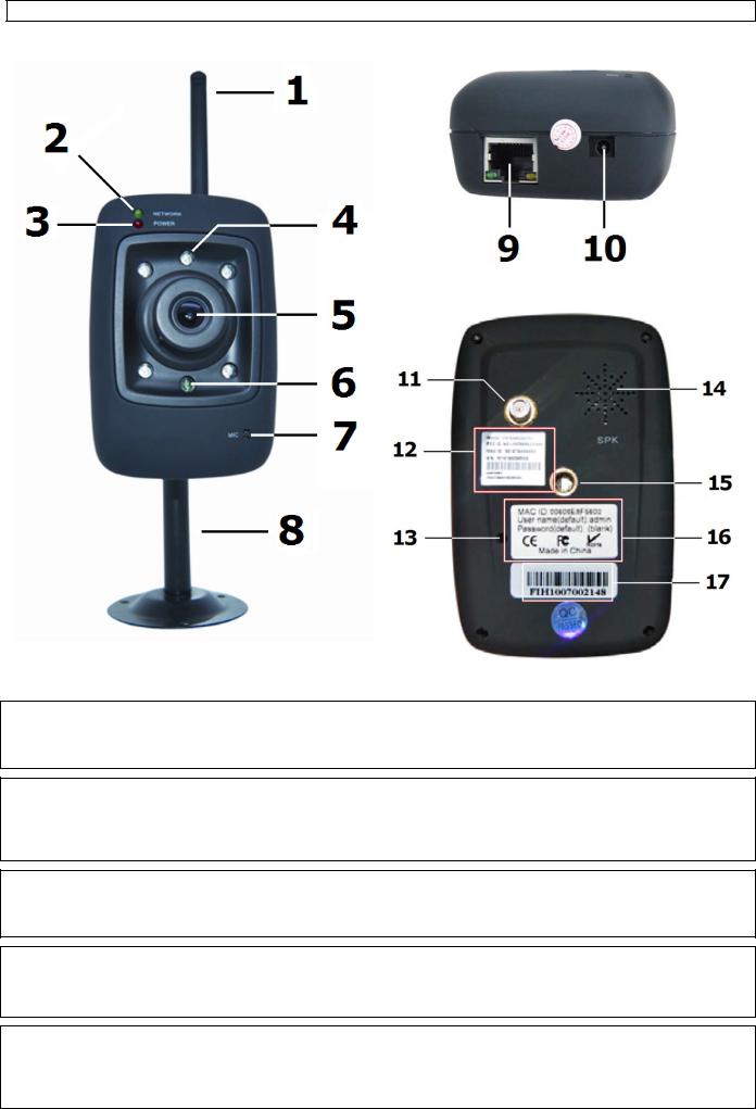
5. Overvie w
Re fer to the illustration s on page |
2 of this m anual. |
|
||
|
|
|
|
|
1 |
Wifi antenna |
|
10 |
5V DC inpu t jack (2A) |
2 |
network LED |
|
11 |
antenna connector |
3 |
power L ED |
|
12 |
MAC address wireless |
4 |
IR LED (5x) |
|
13 |
reset button |
5 |
lens |
|
14 |
speaker |
6 |
light se nsor |
|
15 |
mounting h ole bracket |
7 |
microph one |
|
16 |
MAC address wired |
8 |
mounti ng bracket |
|
17 |
serial num ber |
9 |
RJ45 ne twork jack |
|
|
|
16.12.2011 |
3 |
©Vellema n nv |
CAMIP10
6. Hardware installation and operation
•Choose a location for the camera, keeping following guidelines in mind:
•Do not install the camera in locations where extremely high or low temperatures or excessive vibrations may occur.
•Avoid mounting the camera near high electro-magnetic fields.
•Do not aim the camera at the sun or other extremely bright objects.
•Attach the mounting bracket [8] to the wall or ceiling using the 3 included screws. Place the CAMIP10 on top and secure it with the centre screw [15]. Determine the desired angle and tighten the joint screws.
•Connect the antenna [1] to the antenna connector [11] and/or connect a network cable (included) to the RJ45 jack [9].
Note: it is possible to connect the camera straight to the RJ45 port of a computer. In this case a crossed cable (not incl.) should be used and network settings must be configured manually.
•Plug the DC connector of the power adaptor into the 5VDC input jack [10]. Only use the included adaptor or one with the same specifications.
•Plug the adaptor into a suitable mains outlet (100~240V AC/50~60Hz).
Notes:
•It takes about 30s for the camera to initialise.
•When the image appears out of focus, turn the lens [5] to adjust.
7.Software installation
•Insert the included CD-ROM into a suitable computer system (not incl.).
System requirements: CPU ≥ 2.0 GHz / memory ≥ 256MB / network ≥ 10 MB / video card ≥ 64MB memory / recommended OS: Windows 2000, XP, Vista, 7 or Mac.
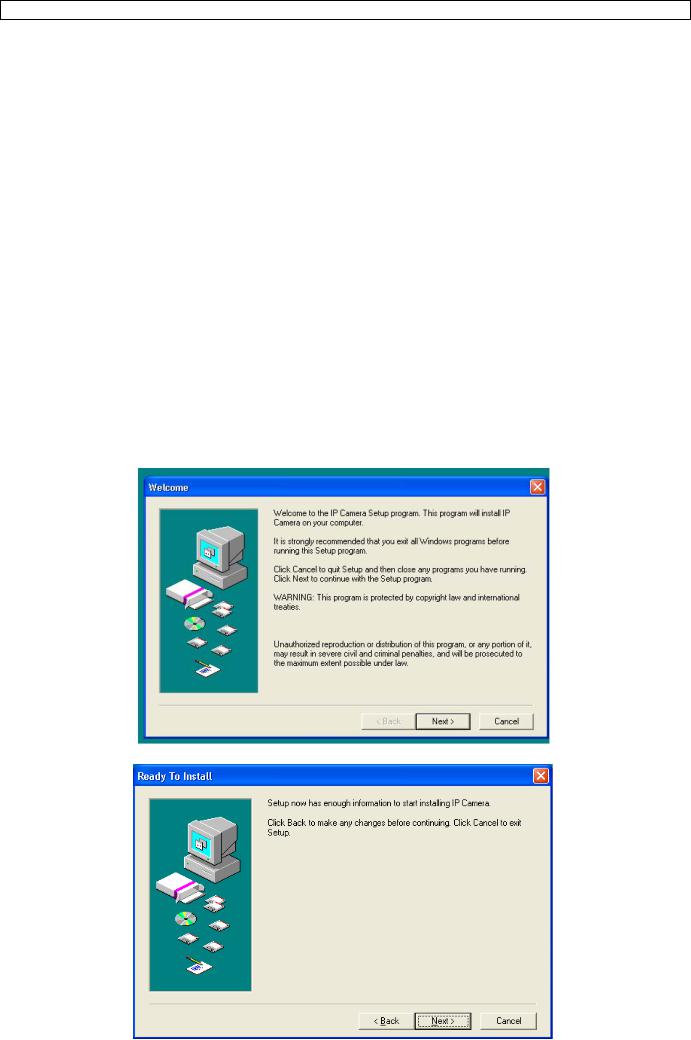
Windows
• Locate the software installer IPCamSetup.exe and double click it.
• Follow the instructions on the screen. Click Next to start the software installation.
16.12.2011 |
4 |
©Velleman nv |

CAMIP10
• Click Next again.
•To finish software installation, the computer must be restarted. Select ‘Yes I want to restart my computer now’ and click on Close.
•After reboot, the IP Camera Tool icon appears on the desktop.
Note: when the icon does not appear on a Windows 7 system, check the path of the camera and adjust it when necessary. The shortcut should point to C:\Windows\SysWOW64\IPCamera.exe
Mac
•Locate and open the folder “For MAC”.
•Open the folder “IP camera Tool” and copy the tool to your MAC to use it.
8. Software set-up
•Make sure all connections are properly made (see also §6) and double click on the IP Camera Tool icon to start the software.
8.1IP Camera Tool
•The software starts searching for cameras over the LAN. 3 Situations can occur:
o No cameras are found on the LAN. If after 1 minute the software does not detect any cameras, check all cabling of the system and make sure the camera is powered.
o Cameras are found and listed (see image below).
o Cameras are found but are not on the same subnet as the PC. The message ‘Subnet doesn’t match, dbclick to change’ appears. Change the subnet settings via the network configuration menu (see further).
Note: make sure DHCP is enabled in the router and MAC address filter is disabled. When problems remain, disable any active firewall or antivirus and try again.
16.12.2011 |
5 |
©Velleman nv |

CAMIP10
Windows:
Mac:
•Open the options menu by right clicking on a listed camera.
Note: only when the camera is fully initialised all options become visible.
Basic properties
• Shown some general information about the camera:
Network Configuration
• View/change the network settings of the camera:
16.12.2011 |
6 |
©Velleman nv |

CAMIP10
•When connected to a DHCP router, check the ‘Obtain IP from DHCP server’ checkbox, otherwise uncheck it and fill in the data manually.
•In case of a subnet mismatch, change the IP-address or subnet mask.
•When in doubt about the network settings, contact a qualified network administrator.
Note:
Upgrade firmware
•Only use this option when problems with the current version are noticed. Do not upgrade if the camera works fine.
•Caution: when the upgrade process is interrupted or a wrong version is installed the camera might not work anymore.
•The administrators’ login and password are required.
Note: default administrator login is admin without a password.
Refresh Camera List
•Use this option to update the camera list, e.g. when a new camera is added to the network.
Flush ARP Buffer
•When both a wireless and wired connection to a camera exists, a problem with the ARP (Address Resolution Protocol) may arise resulting in the camera not being accessible via the browser. In this case the ARP buffer should be cleared
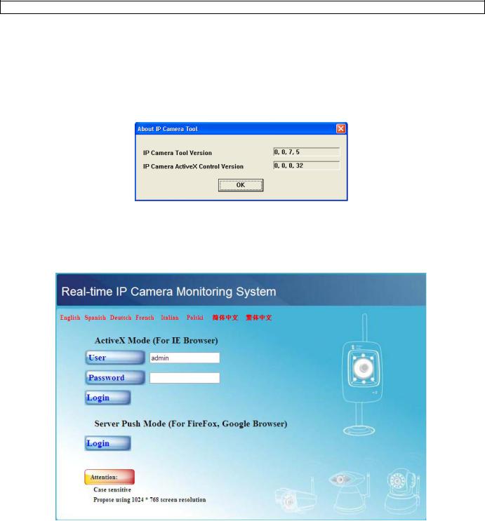
About IP Camera Tool
• Show some extra information about the camera tool.
8.2Camera login
•When the network set-up is completed, double click on the camera to open the camera window. A web browser with a login page is opened:
Note: it is also possible to open a browser window and enter the cameras’ IP address in the address bar.
16.12.2011 |
7 |
©Velleman nv |

CAMIP10
•Enter your account name and password and click Login. Default, the administrator login is admin without a password.
Note: use the upper Login button when your browser supports ActiveX Browser Plug-ins. When using a browser that does not support ActiveX, click on the lower Login button. Some features e.g. full screen, audio, multi-channel image … will not be available.
•When login on to the system with an administrator login password, the For Operator screen opens; login on with a user regular user account will open the For Visitor layout.
Note: when asked for (see title bar), allow the system to run add-in.
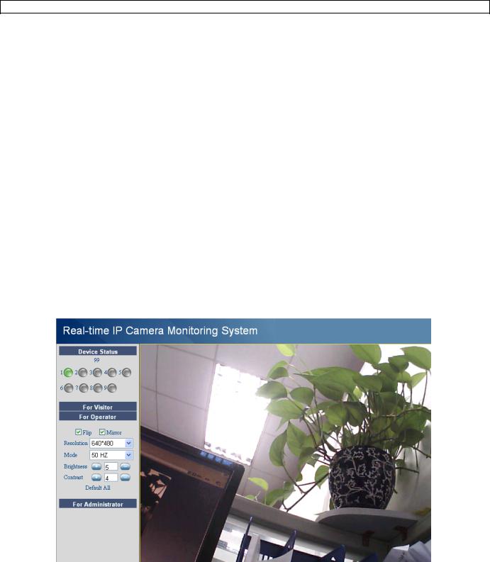
For Visitor layout
•The interface software supports up to 9 cameras. The device status shows the status of each of these 9 cameras. Green = OK, Yellow = camera connection problem, Red = alarm condition.
•Select the preferred screen layout:  shows 1 camera,
  shows 4 cameras and
  shows 9 cameras simultaneously in the camera display pane.
•Set the preferred colour for the On Screen Display (OSD): disabled (no OSD), black, yellow, red, white or blue. The OSD shows the name of the camera in the top right corner of the camera display and a date and time stamp at the bottom.
•When the ‘Add timestamp on record’ checkbox is checked, date and time are shown on the recorded file.
Note: set the time via the For Administrator screen (see further).
16.12.2011 |
8 |
©Velleman nv |
CAMIP10
•Set the audio buffer. The speaker output will be delayed for the indicated number of seconds.
•When the  -icon is shown the alarm record path (see User Settings below) is opened once an alarm triggered recording is finished. Click on the icon to switch this function off. The icon changes into
  .
.
•Press the snapshot button  to take a snapshot of the camera display. In multiple screen layouts, select the desired camera display first by left clicking on it. A new window with the picture is opened. Press the Save button and select the desired location to save the picture.
•Press the view button  to start viewing the camera images, press the stop button
  to stop viewing.
•At the bottom of the left pane, each of the 9 possible cameras has 3 icons. Unavailable cameras are greyed out.
 = audio – talk – record
•Press on the  icon to enable the cameras’ microphone
•Press on the  icon to enable the cameras’ speaker/audio port; a PC microphone (not incl.) is required.
•Press on the  icon to start recording the selected cameras’ images.
Notes:
•When an icon is pressed, it changes to the stop icon  . Press this icon to stop the underlying function.
•The recorded file name is cameraname_timestamp.avi
e.g. Counter_20081211134442.avi
•The path where the movies will be stored can be set by the administrator in the For Administrator screen (see further).
For Operator layout
•When entering an administrator password, the user can open the For Operator layout.
•Check the Flip checkbox in case the image is shown upside down.
•Check the Mirror checkbox to mirror the image.
•Set the resolution to 320*240 or 640*480.
•Set the mode to 50Hz or 60Hz.
Note: the camera is not suitable for outdoor use! The outdoor setting could be used in case the camera is pointed towards a bright natural light source.
•Set the brightness and contrast of the image with the “+” and “-” buttons.
16.12.2011 |
9 |
©Velleman nv |
CAMIP10
For Administrator layout
•The For Administrator layout is only available when logged in with an administrator account. It is used for advanced configuration of the cameras.
Notes:
•Select the desired camera before opening the For Administrator layout.
•Depending on the ticked checkboxes, different data entry fields are shown. Hence the
display you see for a certain option might differ from the images used below.
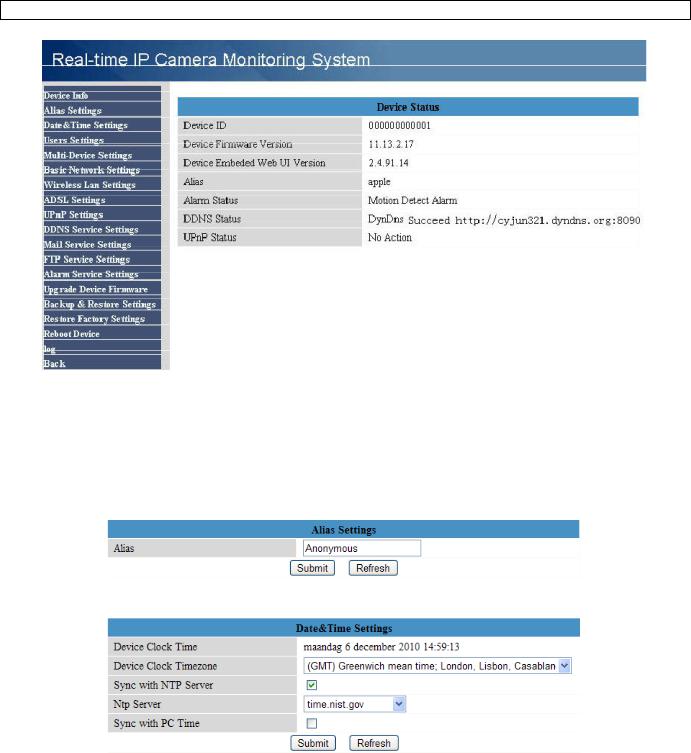
Device info
•Device ID, firmware version and Web User Interface version are shown (see image above).
Alias Settings
•Set the name of the selected camera.
Date&Time Settings
•Set date and time data for the camera.
Note: if the timestamp on the display shows the wrong time, try checking the Sync with PC Time checkbox and press Submit.
16.12.2011 |
10 |
©Velleman nv |
CAMIP10
Users Settings
•Up to 8 users can be configured. Enter a user name, a password and select a group (Visitor, Operator or Administrator). This is also the location to change the administrators’ login name and set a password for the administrator.
•Set the record and alarm record paths using the Browse buttons. Default for both is c:\\Documents and Settings\All Users\Documents
Notes when using Windows Vista,
•Remember to add the IP address of the camera to the ‘Trusted sites’.
•The system does not allow to set the Windows System Root Directory as record or alarm record path.
Multi-Device Settings
•Use this menu to manually add extra cameras (up to 9).
•Select a device by clicking on it and enter an alias, host address, Http port, user name and password:
• Press submit to add the device.
16.12.2011 |
11 |
©Velleman nv |

CAMIP10
Basic Network Settings
•When connected to a DHCP router, check the ‘Obtain IP from DHCP server’ checkbox, otherwise uncheck it and fill in the data manually.
•The ‘Network Lamp’ or network LED [11] indicates the network status of the camera. To disable this LED, uncheck the ‘Network Lamp’ checkbox.
Wireless LAN Settings
•Press the Scan button to retrieve a list of available wireless LANs.
•Click on a found network and enter the password if required.
•When you want to use a wireless LAN, check the checkbox and enter a SSID, Channel and encryption method. Depending on the selected encryption method, more data will have to be provided.
Notes
•Some routers will automatically fill out the necessary data into the fields.
•When entering data manually, check the wireless net settings of your router to find more information on SSID, Channel, encryption and authentication.
ADSL Settings
•When connected to the Internet directly via ADSL, check the checkbox and enter the ADSL User name and ADSL password you obtained from your Internet Service Provider (ISP).
UPnP Settings
• Check the checkbox to use the Universal Plug and Play (UPnP) protocol
16.12.2011 |
12 |
©Velleman nv |
CAMIP10
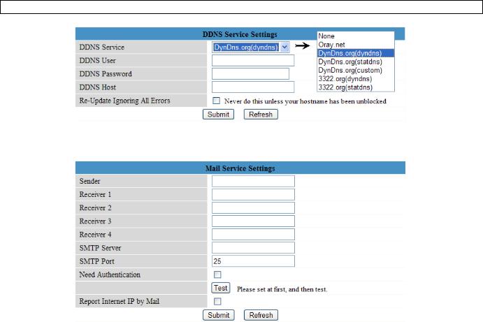
DDNS Service Settings
•Obtain a domain name from a supported DDNS provider (see image above) and enter the data in the appropriate fields.
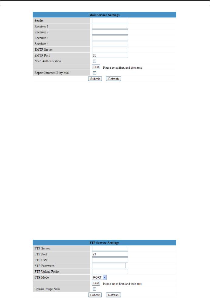
Mail Service Settings
Note: these settings only take effect when the option ‘Send Mail on Alarm’ is checked in the ‘Alarm Service Settings’ menu (see below).
•Fill in a senders e-mail address in the ‘Sender’ field. This is the mailbox from which the mails will be sent.
•Fill in up to 4 receivers mail addresses. When an alarm condition occurs, mail is sent out to these addresses.
•Fill out all SMTP data related to the senders’ mail box. When authentication for the mailbox is required, check the checkbox and enter user name and password in the appropriate fields.
•When the ‘Report Internet IP by Mail’ is checked, a mail is sent whenever a camera comes online (e.g. after reboot) or a change in IP address occurred. Make sure the port is correctly mapped to the router.
•Press ‘Submit’ to store the data before performing a ‘mail test’. Following error messages may pop-up:
• Can not connect to the server
Check network cabling and settings.
• Network error. Please try later.
Check network cabling and settings.
• Server error.
Check the server.
• Incorrect user or password.
Make sure to enter the right user name and password.
• The sender is denied by the server.
Check whether the user needs authentication.
• The receiver is denied by the server.
Could be due to anti-spam settings of the server.
• The message is denied by the server.
Could be due to anti-spam settings of the server.
• The server does not support the authentication mode used by the device.
Try without authentication or use a different server (sender address).
FTP Service Settings
Note: these settings only take effect when the option ‘Upload Image on Alarm’ is checked in the ‘Alarm Service Settings’ menu (see below).
16.12.2011 |
13 |
©Velleman nv |

CAMIP10
•Fill out all FTP server data. The port is usually set to 21.
•Set the FTP mode to standard (PORT) or passive (PASV).
•When desired, check the ‘Upload Image Now’ checkbox and set an upload interval (in seconds).
•Press ‘Submit’ to store the data before performing an ‘FTP test’. A successful test will display ‘FTP test succeeded’. Possible error messages are:
• Can not connect to server.
Check FTP server address
• Network error. Please try later.
Check network cabling and settings.
• Server error.
Check the FTP server
• Incorrect user or password.
Make sure to enter the right user name and password.
• Can not access the folder.
Make sure the folder exists and your FTP account is authorized.
• Error in PASV mode.
Make sure the server supports PASV mode.
• Error in PORT mode.
If the device is behind a NAT (Network Address Translation) device, PASV mode must be selected.
• Can not upload file.
Make sure your FTP account is authorized.
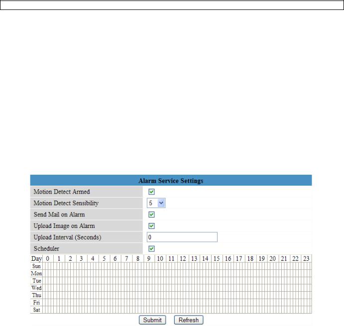
Alarm Service Settings
•Check the ‘Motion Detect Armed’ checkbox to enable motion detection. This also allows mails to be sent out (see Mail Service Settings) and image upload to an FTP server (see FTP Service Settings).
Note: when the camera is in auto tilt/auto pan mode (see For Operator layout), motion detection and external alarm input are disabled!
•The motion detect sensibility van be set between 1 and 10, with 10 being most sensitive.
•Check the ‘Send Mail on alarm’ checkbox to send a mail when an alarm is detected. Make sure to
fill out all fields on the ‘Mail Service Settings’ page (see above).
16.12.2011 14 ©Velleman nv

CAMIP10
•Check the ‘Upload Image on alarm’ checkbox to upload images to an FTP server when an alarm is detected. Make sure to fill out all fields on the ‘FTP Service Settings’ page (see above). When this option is checked, you can also set the upload interval (in seconds).
•Check the ‘Scheduler’ checkbox to open the day schedule. Click on the schedule to set the time during which alarm service must be enabled. Horizontal axis = hours, divided per 15 minutes and Vertical axis = day of the week.
Upgrade Device Firmware
•Only use this option when problems with the current version are noticed. Do not upgrade if the camera works fine.
•Caution: when the upgrade process is interrupted or a wrong version is installed the camera might not work anymore.
•When clicking on Upgrade Device Firmware or Embedded Web UI (User Interface), a brower window is opened. Locate and select the new firmware/web UI.
Backup & Restore settings
•Use this option to create a backup or restore your system configuration.
•To create a backup, click submit and choose a location to store the backup file.
•To restore a previously made backup, click Browse to locate the backup and click Submit to start restore.
Restore Factory Settings
•Selecting ‘OK’ will clear the memory and reset the device to factory settings. All settings, e.g. user settings, mail and FTP settings, alarm schedule… are lost.
Reboot Device
•Select ‘OK’ to reboot the camera.
Note: this will reset the system time. Refer to Date&Time settings.
16.12.2011 |
15 |
©Velleman nv |

CAMIP10
Log
•The log shows an overview of everyone who accessed the IP camera. It is cleared when rebooting the system.
Back
• Use this option to return to the For Visitor or For Operator page layout.
9. Additional user information
9.1 Password
• Default, the administrator login is admin without a password. To enhance security, a new administrator password should be set as soon as possible (see §8.2 under For Administrator layout – Users Settings).
• If the login or password of the administrator(s) are forgotten or corrupt, the system can be reset to factory defaults (admin, no password) by pressing and holding the RESET button [13] at the back of the camera for about 5 seconds.
9.2 WiFi
• Refer to the user manual of your wireless router to obtain network information e.g. SSID, Channel, Security, authentication, encryption…
• Use previously obtained information to configure your CAMIP10 via a fixed network cable (For Administrator – Wireless LAN settings).
• Reboot the CAMIP10.
• Wait at least 30 seconds before unplugging the network cable. Then unplug the power supply.
• Re-insert the power plug.
• After about 30 seconds, the camera should be up and running in WiFi mode.
9.3 Connect the camera on an ADSL network
•Connect the camera to a PC. The easiest way is to use a router. If no router is available, you must use a cross cable (not incl.) to connect the CAMIP10 directly to the PCs’ RJ45 port and set the IP addresses on PC and camera manually.
•Configure the camera with the IP camera tool (see §8.1).
•Log on to the camera as administrator and configure ADSL settings (user name + password).
•Configure the DDNS Service Settings and click ‘Submit’. The camera reboots.
•Connect the camera directly to the ADSL modem. It is now available through the internet by entering the domain name in your internet browser.
Note: set the option ‘Report ADSL IP by mail’ under Mail Service Settings to receive the cameras’ IP address by mail.
9.4 Connect the camera via a router
• Connect the camera to the LAN and configure the camera with the IP camera tool (see §8.1).
• Log on to the camera as administrator and configure DDNS Service Settings.
• Click ‘Submit’ to reboot the camera.
• The camera is now available through the internet by entering the domain name in your internet browser.
9.5 Static IP users
•When using only fixed IP addresses, a DDNS service is not required. There are two ways to find out the static WAN IP address of the camera:
16.12.2011 |
16 |
©Velleman nv |

CAMIP10
oConnect a computer to the same connection as the camera and open a website that tells you what IP address you are on (e.g. www.whatismyip.com).
oLog on to the router and view the status page to find out its WAN IP address. To connect to the IP camera, enter the WAN IP address of the router followed by the port number to which the camera is connected into the address bar of a browser (e.g. http://116.25.51.115:85/). Make sure UPnP is enabled or the camera is added to the routers’ virtual mapping list.
9.6Using DDNS
•DDNS stand for Dynamic Domain Name Server. It is a service that links dynamic IP addresses to fixed domain names. This way, the camera will always be accessible by using a domain name, no matter which IP address was assigned to it.
•To obtain a domain name and password, refer to a DDNS website on the internet.
•Enter the name and password in the DDNS Service Settings page and press ‘Submit’. The camera reboots.
•Check the UPnP settings. If the status is not ‘succeed’, try to change the port number in the Basic Network Settings page. Submit and reboot the camera.
•To connect to the camera, enter domain name of the camera in the address bar of a web browser. The prefix www. is not required. When multiple cameras are connected to the router, add the port number behind the domain name (e.g. http://ipcam. Video.net:85/)
9.7 Using a mobile phone
•When the camera is on a WAN, it is possible to connect to it using a midp2.0 java mobile phone.
•Copy IPCamera.jar from the CD ROM to the phone and install it.
•Run IP camera player.
•Enter alias, hostname or IP, port, user, password and resolution, than click OK.
10.Troubleshooting
IP address
•Always make sure the camera is on the same subnet (same subnet mask) as the PC you are using to configure it
Network configuration
•Check your HTTP server software is configured and running properly.
•If the camera is behind a firewall, make sure the firewall software is allowing inbound connections on port 80. If not, use an alternate port. The same goes for certain anti-spam and anti-virus software packages.
•If the camera is behind a cable/DSL router, make sure to configure port forwarding properly. Refer to the user manual of the router.
No image
•Video streaming is transmitted by the ActiveX controller. If this controller is not installed properly no video image is shown.
•When you install the IP Camera Tool, the ActiveX controller is installed at the same time. Otherwise, download the ActiveX controller from the internet and set the safety properties of your web browser so it accepts ActiveX content.
Slow image
• The frame rate of the shown video depends on a number of external factors, e.g.: o Network bandwidth
o PC performance and display settings
o Number of visitors that are viewing the camera simultaneously
oNetwork equipment (e.g. use a switch in stead of a HUB for multiple IP cameras)
Camera not available via Internet
•Possible reasons may include:
oActiveX controller is not installed/working properly.
Note: a standard Firefox browser does not support ActiveX. However there are plug-inns
available on the Internet.
oThe port of the IP camera is blocked by a firewall or anti-virus software. In this case, try using a different port number.
oPort mapping failed. Either enable UPnP (via UPnP Settings) or edit the routers Virtual map list (refer to the user manual of your router).
16.12.2011 |
17 |
©Velleman nv |

|
|
CAMIP10 |
|
1 1. Technical specificati ons |
|
|
|
|
|
|
|
pi ck-up element |
|
¼" colour CMOS sen sor |
|
le ns |
|
f2.8mm / F1.8 |
|
le ns angle |
|
77° |
|
minimum illumination |
0.5 lux (IR LEDs off) |
|
|
resolution |
|
640 x 480 pixels (30 0 000 pixels) |
|
supported network protocols |
TCP/IP, U DP, IMCP, SMTP, HTT P, FTP, DN S, DDNS, |
|
|
DHCP, PPP oE, GPRS |
|
||
|
|
|
|
wired connection |
|
Ethernet 10/100 Base-T and RJ45 |
|
wireless conn ection |
st andard |
IEEE 802. 11b/g |
|
|
supports WEP, WPA & WPA2 encryption |
|
|
|
|
|
|
|
supports 3 m ethods |
fixed IP, DHCP, PPPoE |
|
network con nection |
|
supports D HCP, installs the IP address automatically |
|
|
|
(plug-and- play netw ork) |
|
audio |
|
built-in microphone |
|
|
compression format |
MJPEG |
|
vi deo |
fra me rate |
15 FPS (V GA), 30 FP S (QVGA) |
|
|
resolution |
640 x 480 (VGA), 320 x 240 (QVGA) |
|
sm artphone support |
|
iPhone, Bl ackberry, a ndroid, Symbian and Windows |
|
|
mobile |
|
|
|
|
|
|
power supply |
|
5Vdc |
|
operating te mperature |
0°C ~ 55°C |
|
|
di mensions |
|
100 x 58 x 38mm |
|
w eight |
|
250g |
|
Us e this de vice with original ac cessories only. Velleman nv cannot be held res ponsible i n the event of damage or injury resulted from (incorrect) use of this d evice. For more info co ncerning this prod uct and the latest v ersion of t his user manual, please visit our
website ww w.velleman.eu. Th e informat ion in thi s manual is subject to chang e without prior notice.
G ebruikershandleiding
1. Inleidi ng
A n alle ingezetenen van de Eu ropese Unie
Be langrijke milieu-informatie betreffend e dit prod uct
Dit symbool op het toestel of de ver pakking geeft aan dat, als het n a zijn levenscyclus word t weggew orpen, dit toestel scha de kan toe brengen aan het mili eu. Gooi dit toestel (en even tuele batte rijen) niet bij het ge wone huishoudelijke afval; het m oet bij een
gesp ecialiseerd bedrijf terechtkomen voor recyclage. U moet dit toe stel naar u w verdeler of naar een lokaal recyclagepunt brengen. Respec teer de pla atselijke m ilieuwetgeving.
H ebt u vragen, contacteer dan de plaatselijke aut oriteiten b etreffende de verw ijdering.
Da nk u voor uw aankoop! Lees deze handleid ing grondig voor u h et toestel i n gebruik neemt. Werd het toestel b eschadigd tijdens het transport, installeer et dan niet en raadpleeg uw dealer.
Le es ook zeker het ad dendum a chteraan deze han dleiding.
2. Veiligheidsinst ructies
Houd buiten h et bereik van kindere n en onbevoegden.
Ele ktrocutiegevaar bij het openen van het t oestel. Ra ak geen kabels aan die onder stroom staan om dodelijke elektros hocks te vermijden. Open de be huizing ni et zelf en la at rep araties ov er aan gesc hoold pers oneel.
De behuizin g mag NOOIT geop end worde n. Er zijn geen door de gebruiker
ver vangbare onderdelen in dit toestel. Voor onderhoud of reserveonderdelen, contactee r uw dealer.
16.12.2011 |
18 |
©Vellema n nv |
CAMIP10
3. Algeme ne richtlijnen
Ra adpleeg d e Vellema n® serviceen kwaliteitsgarantie achte raan deze handleiding .
Enkel voor gebruik binnenshuis. Bescherm tege n regen, vo chtigheid en opspatte nde vloeist offen.
Bescherm tegen stof en extre me hitte.
Bescherm tegen sch okken en vermijd bru te kracht tijdens de b ediening.
• |
Leer eerst de functies van het toestel ken nen voor u het gaat gebruiken. |
• |
Om veiligh eidsreden en mag u g een wijzigingen aanbrengen. Schade door wijziginge n die de |
|
gebruiker heeft aangebracht valt niet ond er de garan tie. |
•Gebruik h et toestel enkel waarv oor het gemaakt is. Bij onoordeelkundig gebruik verv alt de garantie.
• De garantie geldt nie t voor sch ade door h et negeren van bepaalde richtlijn en in deze handleidin g en uw dea ler zal de verantwoordelijkheid afwijzen vo or defecte n of problemen die hi er rechtstreeks verband mee houd en.
4. Eigensc happen
• eenvoudig te installeren
• beveiligde Wi-Fi-aan sluiting en bekabelde LAN-aansl uiting
• nachtzicht dankzij 5 infraroodleds
• ingebouw de microfoo n en luids preker
• alarmberic ht bewegi ngswaarne ming via e- mail of up oad van b eelden naar FTP
5. Omsch rijving
Ra adpleeg d e afbeeldin gen op pagina 2 van deze handleiding.
1 |
Wi-Fi-a ntenne |
10 |
5 VDC ingangsaansluiting (2 A) |
2 |
netwerk led |
11 |
antenneaa nsluiting |
3 |
voedingsled |
12 |
draadloos MAC adres |
4 |
infraroodleds (5x) |
13 |
reset knop |
5 |
lens |
14 |
luidspreker |
6 |
lichtsensor |
15 |
schroefgat beugel |
7 |
microfoon |
16 |
MAC adres vaste lijn |
8 |
montagebeugel |
17 |
serienummer |
9RJ45-aa nsluiting
6.De har dware installere n en gebruiken
• Kies een g eschikte m ontagepla ats voor de camera e n houd rek ening met volgende punten:
• |
montee r de came ra nooit op een plaats onderhevig aan extr eme tempe raturen en trillingen; |
• |
montee r de came ra nooit in de buurt v an elektrom agnetische velden; |
• |
richt de camera n ooit naar de zon of na ar andere weerkaats ende objecten toe; |
• Monteer de montage beugel [8] met behul p van de drie meegeleverde schroeven. Bevestig de camera aan de mont agebeugel [8] met de centrale s chroef [15 ]. Richt de camera.
•Steek de a ntenne [1 ] in de aansluiting [1 1] en/of ste ek de meegeleverde netwerkkab el in de RJ45-aansluiting [9] .
Opmerkin g: U kunt de camera rechtstree ks op de RJ45-aanslui ting van de computer aansluiten. Gebr uik hiervoo r een gekruiste kabel (niet meeg eleverd). De camera moet daar a handmatig inge steld worde n.
•Steek de v oedingsstekker van de voedingsadapter in de 5VDC-in gang [10]. Gebruik enkel de meegeleve rde adapte r of een ad apter met dezelfde eigenschappen.
• Steek de v oedingsad apter in he t stopcontact (100 ~ 2 40 VAC/50 ~ 60 Hz).
O pmerking en:
• De initialisatie van de camera duurt ee n 30-tal se conden.
•Regel de lens [5] bij indien u een onscherp beeld krijgt.
7.De software ins talleren
• Steek de meegelever de cd-rom in de cd-r omdrive van uw comp uter.
Systeemvereisten: CPU ≥ 2,06 GHz / geh eugen ≥ 2 56 MB / ne twerk ≥ 10 MB / grafische kaart ≥ 64 MB / aanbevole n besturin gssysteem : Windows 2000 of XP / Mac.
16.12.2011 |
19 |
©Vellema n nv |

CAMIP10
Windows
• Dubbelklik op IPCamSetup.exe om de software te installeren.
• Volg de instructies op het scherm. Klik op Next om de installatie te starten.
• Klik opnieuw op Next.
16.12.2011 |
20 |
©Velleman nv |
CAMIP10
•Herstart de computer om de installatie te voltooien. Vink Yes I want to restart my computer now aan en klik op Close.
•Na de herstart verschijnt IP Camera Tool op het bureaublad.
Opmerking: indien het icon niet verschijnt op een Windows 7 systeem, controleer dan het pad van de camera en pas aan indien nodig. De shortcut moet verwijzen naar: C:\Windows\SysWOW64\IPCamera.exe
Mac
•Open de folder “For MAC”.
•Open de folder “IP camera Tool “ en kopieer de tool naar uw Mac.
8. De software configureren
• Dubbelklik op IP Camera Tool om de software te starten.
8.1IP Camera Tool
•De software zoekt automatisch naar de beschikbare camera’s op het LAN-netwerk. Er zijn 3 mogelijkheden:
o Er zijn geen camera’s beschikbaar. Controleer de bekabeling en zorg dat de camera is ingeschakeld indien de software na 1 minuut geen enkele camera heeft gevonden.
o Er zijn camera’s beschikbaar en ze staan opgelijst (zie afbeelding hieronder).
o Er zijn camera’s beschikbaar maar ze staan niet op hetzelfde subnet als deze van uw computer. Het bericht Subnet doesn’t match, dbclick to change verschijnt. Wijzig de configuratie van het subnet via het configuratiemenu van het netwerk (zie verder).
Opmerking: Zorg dat het DHCP in de router ingeschakeld is en de MAC-adresfiltering uitgeschakeld is. Bij blijvende problemen, schakel alle actieve firewalls of antivirussoftware uit en probeer opnieuw.
Windows:
Mac:
16.12.2011 |
21 |
©Velleman nv |

CAMIP10
• Open het optiemenu door met de rechtermuisknop op een camera in de lijst te klikken. Opmerking: De opties zijn enkel zichtbaar na de volledige initialisatie van de camera.
Basiseigenschappen (Basic properties)
• Algemene informatie over de camera:
Netwerkconfiguratie (Network Configuration)
• Een overzicht van de netwerkinstellingen van de camera:
•Vink Obtain IP from DHCP server aan indien aangesloten op een DHCP-router. Indien niet, vink uit en geef de data handmatig in.
•Wijzig het IP-adres of het subnetmasker bij een ongeldig subnetadres.
•Neem bij twijfel over de subnetinstellingen contact op met een netwerkbeheerder.
De firmware upgraden (Upgrade firmware)
•Het is aanbevolen om de firmware te upgraden enkel en alleen indien u problemen ondervindt met de huidige versie. U hoeft de de firmware niet te upgraden indien de camera normaal functioneert.
Opgelet: U kunt de camera ernstig beschadigen indien het upgradeproces onderbroken wordt of een verkeerde versie wordt geïnstalleerd.
•Geef de login en het wachtwoord van de beheerder in. Opmerking: De standaard login is admin zonder wachtwoord.
16.12.2011 |
22 |
©Velleman nv |
CAMIP10
De cameralijst verversen (Refresh Camera List)
•Ververs de lijst wanneer u een nieuwe camera aan het netwerk toevoegt.
ARP-buffer wissen (Flush ARP Buffer)
•Bij zowel een draadals een draadloze aansluiting kunnen zich problemen voordoen met het ARP (Address Resolution Protocol) en kan de camera via de browser niet beschikbaar zijn. Wis in dit geval de ARP-buffer.
Over de camera (About IP Camera Tool)
• Bijkomende informatie over de camera.
8.2Login van de camera
•Dubbelklik na de volledige configuratie van het netwerk op de camera. Er verschijnt een webbrowser met aanmeldpagina:
Opmerking: U kunt het IP-adres van de camera ook in de adresbalk van een webbrowser ingeven.
•Geef uw accountnaam en wachtwoord in en klik daarna op Login. De standaard login is admin zonder wachtwoord.
Opmerking: Gebruik de aanmeldknop bovenaan indien uw browser ActiveX gebruikt. Gebruikt u een browser dat ActiveX niet ondersteunt, klik dan op de onderste aanmeldknop.
Merk op dat sommige functies zoals een volledige schermweergave en een audio dan niet beschikbaar zijn.
•Bij het inloggen met een administratorpaswoord verschijnt het venster For Operator. Bij het inloggen met een gebruikerspaswoord verschijnt het venster For Visitor.
Opmerking: indien gevraagd, (zie taakbalk), laat toe de add-in te starten.
16.12.2011 |
23 |
©Velleman nv |

CAMIP10
For Visitor (bezoeker)
•De software ondersteunt tot 9 camera’s. Onder Device Status ziet u de status van elke aangesloten camera: groen = oké, geel = aansluitingprobleem, rood = alarm.
•Kies de gewenste schermlay-out:  = 1 camera,
  = 4 camera’s,
  = 9 camera’s.
•Kies de gewenste kleur voor het OSD-menu: disabled (geen OSD), zwart, geel, rood, wit of blauw. De OSD geeft de cameranaam rechtsboven het scherm weer; datum en tijd verschijnen onderaan.
•Vink Add timestamp on record aan om datum en tijd op de opname weer te geven. Opmerking: Stel de tijd in via het For Administrator-menu (zie verder).
•Stel de audiobuffer in. De luidspreker wordt gedurende het aantal ingestelde seconden uitgeschakeld.
•Bij het verschijnen van de icoon  worden alarmen opnamepad (zie Gebruikersinstellingen hieronder) geopend van zodra de opname wordt beëindigd. Klik op de icoon om deze functie uit te schakelen. De icoon wijzigt in
  .
.
•Druk op  voor een screenshot. Selecteer eerst de gewenste camera door met de linkermuisknop op de beeldweergave te klikken. Er verschijnt een nieuw scherm met daarin de screenshot. Druk op Save en selecteer de doelmap om de screenshot te bewaren.
•Druk op  om de beeldweergave van een camera in te schakelen of op
  om de beeldweergave uit te schakelen.
•Onderaan het linkerpaneel vindt u voor de 9 camera’s telkens 3 iconen:  = audio – spraak
– opname. Niet-beschikbare camera’s zijn wazig gemaakt.
•Schakel de microfoon van de camera in met  .
.
•Schakel de luidspreker van de camera in met  . Voor deze functie moet u een microfoon (niet meegeleverd) op uw computer aansluiten.
•Druk op  om de opnamefunctie voor die camera in te schakelen.
Opmerkingen:
•Bij het aanklikken van een icoon verandert de icoon  . Druk op deze icoon om zijn functie uit te schakelen.
•De bestandsnaam van de opname wordt cameranaam_tijdsaanduiding.avi.
Bv. ingang_20081211134442.avi.
•Het pad waaronder de opnames bewaard worden, zijn door de beheerder onder For Administrator instelbaar (zie verder).
16.12.2011 |
24 |
©Velleman nv |

CAMIP10
For Operator (gebruiker)
•Bij het inloggen met wachtwoord verkrijgt u toegang tot het gebruikersmenu For Operator.
•Vink Flip aan om het beeld om te draaien.
•Vink Mirror om het beeld te spiegelen.
•Stel de resolutie in op 320*240 of 640*480.
•Stel de snelheid in op 50 Hz of 60 Hz.
Opmerking: Deze camera is niet geschikt voor gebruik buitenshuis! Gebruik de instellingen voor buitenshuis indien de camera naar een heldere lichtbron is gericht.
•Stel helderheid en contrast van het beeld in met + en –.
For Administrator (beheerder)
• Het beheerdermenu For Administrator is enkel beschikbaar indien u inlogt met beheerderwachtwoord. Dit menu beschikt over geavanceerde instelmogelijkheden.
Opmerkingen:
•Kies de gewenste camera alvorens het beheerdermenu te openen.
•Verscheidene invoervelden zijn beschikbaar naargelang de aangevinkte vakjes. De
afbeeldingen hieronder kunnen dus verschillen met de werkelijkheid.
Cameragegevens (Device info)
• ID-nummer, versie van de firmware en van de gebruikersinterface (zie afbeelding hierboven).
16.12.2011 |
25 |
©Velleman nv |

CAMIP10
Aliasinstellingen (Alias Settings)
• Geef hier de naam van de camera in.
Datumen tijdsinstellingen (Date&Time Settings)
•Stel hier datum en tijd in.
Opmerking: Vink Sync with PC Time aan en druk op Submit bij een verkeerde tijdsaanduiding
op de display.
Gebruikersinstellingen (Users Settings)
•Als beheerder kunt u tot 8 gebruikers beheren. Geef gebruikersnaam en wachtwoord in en selecteer een groep (Visitor, Operator of Administrator). Hier kunt u ook uw aanmeldnaam en wachtwoord wijzigen.
•Stel het opnameen alarmpad in met Browse. Standaard is dit pad C:\Documents and
Settings\All Users\Documents.
Opmerkingen voor Windows Vista®-gebruikers:
•Geef ook het IP-adres in van vertouwde websites.
•U kunt de Windows-rootfolder niet als opnameof alarmpad instellen.
16.12.2011 |
26 |
©Velleman nv |

CAMIP10
Instellingen voor meerdere camera’s (Multi-Device Settings)
•Gebruik dit menu om handmatig tot 9 camera’s toe te voegen.
•Selecteer een camera door deze te aan te klikken en een alias, een bezoekersadres, een httppoort, een gebruikersnaam en een wachtwoord in te geven:
• Druk op Submit om de camera toe te voegen.
Basisinstellingen van het netwerk (Basic Network Settings)
•Vink Obtain IP from DHCP server aan indien aangesloten op een DHCP-router. Indien niet, vink uit en geef de gegevens handmatig in.
•Network Lamp geeft de status van de camera in het netwerk weer. Vink uit om de led [11] uit te schakelen.
16.12.2011 |
27 |
©Velleman nv |

CAMIP10
Instellingen draadloos LAN
•Druk op Scan om een lijst weer te geven van alle beschikbare draadloze LAN-netwerken.
•Klik op het beschikbare netwerk en geef indien nodig het wachtwoord in.
•Vink Using Wireless Lan aan en geef een SSID, het kanaal en de encryptie in indien u een draadloos LAN-netwerk wenst te gebruiken. U zult meer gegevens moeten ingeven afhankelijk van de geselecteerde encryptie.
Opmerkingen:
•Bepaalde routers geven automatisch de nodige gegevens in.
•Raadpleeg de draadloze netwerkinstellingen van de router voor meer informatie over SSID, kanaal, encryptie en authenticatie bij een handmatige invoer van de gegevens.
ADSL-instellingen (ADSL Settings)
•Vink aan en geef gebruikersnaam en ADSL-wachtwoord in bij aansluiting via ADSL. Deze gegevens zijn verkrijgbaar bij uw internetprovider.
UPnP-instellingen (UPnP Settings)
• Vink aan om het UPnP-protocol (Universal Plug and Play) te gebruiken.
Instellingen DDNS Service (DDNS Service Settings)
•Vraag een domeinnaam aan bij uw DDNS-provider (zie afbeelding hieronder) en geef de gegevens in de daartoe bestemde velden in.
16.12.2011 |
28 |
©Velleman nv |
CAMIP10
E-mailinstellingen (Mail Service Settings)
Opmerking: Deze instellingen zijn enkel geldig indien de optie Send Mail on aangevinkt is in het menu Alarm Service Settings (zie hieronder).
•Geef het adres in van de afzender in het veld Sender. Dit is de mailbox waaruit de e-mails worden verzonden.
•U kunt tot 4 ontvangadressen ingeven. Bij alarm wordt een e-mail naar elk van de ingegeven adressen verzonden.
•Geef alle SMTP-gegevens in. Bij authenticatie van de mailbox, vink het vakje aan en geef gebruikersnaam en wachtwoord in.
•Vink Report Internet IP by Mail aan om een e-mail te krijgen van zodra de camera online beschikbaar is (bv. na een herstart) of bij wijziging van het IP-adres.
•Druk op Submit om de gegevens te bewaren alvorens het systeem te testen. Volgende foutmeldingen zijn mogelijk:
• Geen aansluiting met de server.
Controleer de bekabeling en de instellingen van het netwerk.
• Netwerkfout. Probeer het later opnieuw.
Controleer de bekabeling en de instellingen van het netwerk.
•Serverfout. Controleer de server.
•Gebruikersnaam of wachtwoord niet correct.
Geef uw gebruikersnaam en wachtwoord correct in.
• Afzender geweigerd door de server.
Controleer of de gebruiker authenticatie hoeft.
•Bestemmeling geweigerd door de server. Controleer de antispaminstellingen van de server.
•Bericht geweigerd door de server.
Controleer de antispaminstellingen van de server.
• De server ondersteunt geen authenticatie.
Probeer zonder authenticatie of gebruik een andere server.
Instellingen FTP Service (FTP Service Settings)
Opmerking: Deze instellingen zijn enkel geldig indien de optie Upload Image on Alarm aangevinkt is in het menu Alarm Service Settings (zie hieronder).
•Geef alle FTP-gegevens in. De FTP-poort is doorgaans 21.
•Stel FTP Mode in op standaard (PORT) of passief (PASV).
•Indien gewenst, vink Upload Image Now aan en stel een interval in (in seconden).
16.12.2011 |
29 |
©Velleman nv |
CAMIP10
•Druk op Submit om de gegevens te bewaren alvorens het systeem te testen. Volgende foutmeldingen zijn mogelijk:
• Geen aansluiting met de server.
Controleer het adres van de FTP-server.
• Netwerkfout. Probeer het later opnieuw.
Controleer de bekabeling en de instellingen van het netwerk.
• Serverfout.
Controleer de FTP-server.
• Gebruikersnaam of wachtwoord niet correct.
Geef uw gebruikersnaam en wachtwoord correct in.
• Toegang tot de map geweigerd.
Zorg ervoor dat de map bestaat en dat uw FTP-account toegang heeft.
• Fout in PASV-modus.
Zorg ervoor de server de PASV-modus ondersteunt.
• Fout in PORT-modus.
Selecteer de PASV-modus indien uw router zich achter een NAT (Network Address Translation) bevindt.
• Upload van het bestand geweigerd.
Zorg ervoor dat uw FTP-account toegang heeft.
Alarminstellingen (Alarm Service Settings)
•Vink Motion Detect Armed aan om de bewegingswaarnemingfunctie in te schakelen. Hierdoor zult u ook e-mails ontvangen (zie: E-mailinstellingen) en beelden naar een FTP-server kunnen uploaden (zie: Instellingen FTP Service).
Opmerking: Tijdens het automatisch afscannen (zie: For Operator), zijn de bewegingswaarneming en de externe alarmingang uitgeschakeld!
•Stel de gevoeligheid van de sensor in tussen 1 en 10 (10 = hoogste gevoeligheid).
•Vink Send Mail on alarm aan om een e-mail te versturen bij alarm. Vul alle gegevens in onder
Mail Service Settings (zie hierboven).
•Vink Upload Image on alarm aan om beelden te uploaden naar een FTP-server bij alarm. Vul alle gegevens in onder FTP Service Settings (zie hierboven). Indien u deze functie inschakelt, dan kunt u ook het uploadinterval instellen (in seconden).
•Vink Scheduler aan om het programmeermenu te openen. Programmeer de tijdruimte waarin u de bewegingswaarnemingfunctie wenst in te schakelen: horizontale as = uren per 15 minuten, verticale as = weekdag.
Upgrade van de firmware (Upgrade Device Firmware)
•Het is aanbevolen om de firmware te upgraden enkel en alleen indien u problemen ondervindt met de huidige versie. U hoeft de de firmware niet te upgraden indien de camera normaal functioneert.
•Opgelet: U kunt de camera ernstig beschadigen indien het upgradeproces onderbroken wordt of een verkeerde versie wordt geïnstalleerd.
16.12.2011 |
30 |
©Velleman nv |
 Loading...