


 Loading...
CTC1000
GSM BASED WIRELESS HOME ALARM SYSTEM DRAADLOOS ALARMSYSTEEM MET GSM-MODULE SYSTÈME D'ALARME SANS FIL AVEC MODULE GSM SISTEMA DE ALARMA INALÁMBRICO CON MÓDULO GSM DRAHTLOSE ALARMANLAGE MIT GSM-MODUL
SISTEMA DE ALARME SEM FIOS POR GSM PARA HABITAÇÃO
USER MANUAL |
3 |
GEBRUIKERSHANDLEIDING |
38 |
MODE D'EMPLOI |
74 |
MANUAL DEL USUARIO |
111 |
BEDIENUNGSANLEITUNG |
147 |
MANUAL DO UTILIZADOR |
183 |
CTC1000
V. 01 – 12/06/2013 |
2 |
©Velleman nv |
CTC1000
USER MANUAL
1.Introduction
To all residents of the European Union
Important environmental information about this product
This symbol on the device or the package indicates that disposal of the device after its lifecycle could harm the environment. Do not dispose of the unit (or batteries) as unsorted municipal waste; it should be taken to a specialized company for recycling. This device should be returned to your distributor or to a local recycling service. Respect the local environmental rules.
If in doubt, contact your local waste disposal authorities.
Thank you for choosing Velleman! Please read the manual thoroughly before bringing this device into service. If the device was damaged in transit, don't install or use it and contact your dealer.
Package contents
Control panel
Power adapter
Ni-Mh rechargeable battery
Optional
PIR motion sensor (order code CTC1000PIR)
door contact (order code CTC1000DS)
remote keypad (order code CTC1000KP)
remote control (order code CTC1000RC)
water sensor (order code CTC1000WS)
external bell box (order code CTC1000SO)
wireless siren (order code CTC1000SI)
2.Safety Instructions
Keep the device away from children and unauthorised users.
Indoor use only.
Keep this device away from rain, moisture, splashing and dripping liquids.
Remove power before opening the cover. Be very careful, touching live wires can cause life-threatening electroshocks.
Damage caused by disregard of certain guidelines in this manual is not covered by the warranty and the dealer will not accept responsibility for any ensuing defects or problems.
Keep the device away from splashing and dripping liquids.
Note that damage caused by user modifications to the device is not covered by the warranty.
This system can provide valuable protection for your home and property if used properly. However, it cannot guarantee complete protection against burglary or robbery. Therefore, VELLEMAN nv will not be responsible for any losses or damages which occur during the use of this product.
3.General Guidelines
Refer to the Velleman® Service and Quality Warranty on the last pages of this manual.
Have the system installed by a qualified installer.
Respect the legislation in your region when installing an alarm system. If necessary, refer to local authorities.
Protect this device from shocks and abuse. Avoid brute force when operating the device.
Protected the device against extreme heat, dust and moisture.
V. 01 – 12/06/2013 |
3 |
©Velleman nv |

CTC1000
Familiarise yourself with the functions of the device before actually using it.
All modifications of the device are forbidden for safety reasons.
The device does not contain any user-serviceable parts except for the battery.
Only use the device for its intended purpose. Using the device in an unauthorised way will void the warranty.
4.Features
30-zone full featured wireless control panel with built-in GSM dialler
SMS messages
up to 6 different phone numbers can be pre-stored in the system and dialled to call for help, in order of priority
1 recordable general message with a capacity of 10 seconds
4 fixed alarm messages for burglar, emergency, fire, and medical alarms
call acknowledgement by recipient ensures the calls are received
listen-in feature allows the call recipient to listen in to what is happening on your side
SMS editing: 14 characters x 4 lines = 56 characters in total
remote command and access to the system from anywhere via SMS
16 x 2 characters backlit full text LCD display
each of the 30 zones can be individually named/edited by the user for quick recognition of designated areas
built-in transmitter to activate outdoor bell box or wireless siren
"home" arming option offers full protection while you are at home, yet allows you to move freely inside without triggering the alarm
full supervision to ensure problem-free operation
door open/close monitoring before system arming adds extra security
error detection and display
tamper detection protects the unit from unauthorized opening or removal from its mounting surface
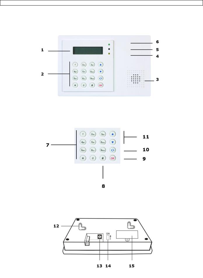
5.Overview
Refer to the illustrations on page 2 of this manual.
1 |
display |
|
|
2 |
keypad |
|
|
3 |
buzzer |
|
|
4 |
yellow LED |
|
- on: an error is detected |
|
- off: no errors, the control panel is in normal mode |
|
|
5 |
microphone |
|
|
6 |
green LED |
|
- on: AC power is on |
|
- off: AC power failure |
|
|
7 |
letters and digits |
|
|
8 |
#: used to enter Program mode |
|
|
9 |
OK: confirms data or selection |
|
|
10 |
Cancel: used in Program mode: cancels a selection, returns to a previous screen... |
|
|
11 |
up and down arrows: used in Program mode: moves the cursor up and down to select an item |
|
|
12 |
2 mounting holes and tamper |
|
|
13 |
DC jack |
|
|
14 |
battery switch |
|
|
15 |
SIM card compartment |
|
|
V. 01 – 12/06/2013 |
4 |
©Velleman nv |

CTC1000
6.Installation
6.1SIM card (optional)
You can insert a SIM card in the control panel to send alarm reports to your mobile phone (up to six numbers).
Before you start
Before inserting the SIM card in the control panel and mounting it, it is recommended to test the country code format used by your mobile phone provider. See section Country Code in chapter 10.
Use your phone to remove the pin code from the SIM card.
Inserting a SIM card
The SIM card holder is located at the back of the device.
To insert your SIM card:
1.Unscrew the SIM card compartment.
2.Slide the holder to the right to open it (see the OPEN mark on the holder).
3.Open the holder and insert your SIM card.
4.Slide the holder to the left to close it (see the CLOSE mark on the holder).
5.Close the compartment using the screw.
6.2Power supply
Use the included AC power adapter to connect the control panel to a wall outlet.
Be sure only to use an adapter with the appropriate AC voltage rating to prevent component damage (see Technical Specifications below for details).
Rechargeable battery
A rechargeable battery (included, see Technical Specifications below for details) inside the control panel serves as a backup in case of power failure.
During normal operation, the AC power adapter is used to supply power to the control panel and at the same time recharge the battery.
When the battery is fully charged, it can provide back-up power for at least 8 hours. It takes approximately 48 hours to fully charge the battery.
WARNING
Do not puncture or throw batteries in fire as they might explode.
Keep batteries away from children.
Backlit display
The device has a backlit LCD display for easy operation in the dark. However, when AC power is missing and for the reason of conservation of rechargeable battery, Backlit feature will be disabled until the AC power is supplied again.
6.3Mounting the control panel
Find a suitable location: requirements
Take the following requirements into account when choosing a suitable location for the control panel.
The control panel requires mains power.
The control panel should be easily accessible.
Do not install the control panel in a damp place (bathroom...)
Do not install the control panel close to a heat source.
Do not install the control panel alongside other radio transmitting devices such as mobile phones, cordless phone or wireless computer network (Wi-Fi) devices.
Mounting the control panel
The control panel can be mounted on the wall or wherever desired. Make sure the control panel is fitted at approximately chest height where the display can be easily seen and the keypad convenient to operate.
1.Use the 2 holes of the wall bracket to mark off the holes‟ positions.
2.Drill 2 holes and insert the wall plugs if fixing into plaster or brick.
3.Screw the base to the wall
V. 01 – 12/06/2013 |
5 |
©Velleman nv |

CTC1000
4.Insert the power supply in the power jack before attaching the panel to the wall.
5.Hook the control panel onto the wall bracket (holding the unit with the front facing you).
6.4Two level passwords
In order to provide highest security in operating the system, the control panel has 2 levels of authorization. When you want to program the system, you have to enter your pin code as well as a master code.
When the control panel asks you to key in ENTER CODE or P-CODE, please enter your user pin code. When the display panel asks you to key in M-CODE, please enter your master code.
For details about the pin code, see section 7.4 Pin code.
For details about the master code, see section 7.7 Master Code.
6.5First use
Assuming you have found a suitable location:
1.Apply the AC power to the control panel. You will hear a long beep. Alarm On will be displayed on the first line and 00:01 01 Jan displayed on the second line of the screen indicating the system is in Away Mode (this is the default Mode)
2.Press button 1 on the keypad.
3.Key in the pin code for user 1 (default code is 1234) within 30 seconds. You can press  to clear the code.
4.Press the OK key (within 30 seconds).
You will hear 2 short beeps and the display will show:
The system is now in alarm off mode.
5.Wait for 2 to 3 minutes for the system to read it status. If the yellow LED turns on, it indicates that there is an error. Refer to section 14 for details.
Notes
The control panel has a screen saver function.
The Alarm off message will be displayed for 180 seconds. After that, the display shows only current date and time.
7.Configuration
To enter Program mode:
1.Make sure the alarm is off (see section 11.4).
2.Press the # key. The display shows:
3.Within 30 seconds, key in 1234 (default User1 pin code) and press OK. The display shows:
4.Within 30 seconds, enter 1111 (default Master Code) and press OK. For 2 seconds, the display shows:
5.Then the program menu will be displayed:
V. 01 – 12/06/2013 |
6 |
©Velleman nv |

CTC1000
It is highly recommended to change the User 1 pin code and the master code on first use.
Cursor
The cursor is indicated by a flashing dot in the left upper corner.
Use the keys and to move the cursor.
Press OK to confirm.
The Program menu contains the following items:
Notes
A down arrow V indicates that the list can be scrolled down. The arrow disappears when you reach the bottom of the list.
An up arrow Λ indicates that the list can be scrolled up. The arrow disappears when you reach the top of the list.
Press Cancel  to return to the Alarm Off display.
In Program mode, if no key is pressed within 5 minutes, the control panel will automatically return to alarm off mode.
7.2Tel. Setting
In the Tel. Setting menu, you can add, change or delete the mobile phone numbers.
The control panel will use these numbers to report events.
You can add up to 6 numbers.
Notes
The display only shows the first 11 digits of a number.
The numbers are listed in order of priority. The system will connect to the phone numbers in that order. If the control panel fails to connect to the first number, it will try the next one on the list.
To add a phone number
1.Enter Program mode and select Tel. Settings from the menu.
The display lists the phone numbers. This list is empty on first use.
2.Use the arrow keys to select the letter to which you want to assign a number (A to F) and press OK.
3.Key in the phone number and press OK.
o The number can contain up to 20 digits and characters * & #. o When entering a number, the key  acts as backspace.
V. 01 – 12/06/2013 |
7 |
©Velleman nv |

CTC1000
To change a phone number
1.Enter Program mode and select Tel. Settings from the menu. The display lists the phone numbers.
2.Use the arrow keys to select the number you want to change and press OK. This will clear the phone number.
3.Key in the phone number and press OK.
o The number can contain up to 20 digits and characters * & #. o When entering a number, the key  acts as backspace.
To delete a phone number
1.Enter Program mode and select Tel. Settings from the menu. The display lists the phone numbers.
2.Use the arrow keys to select the number you want to delete and press OK.
3.Press OK again.
The number is deleted.
7.3General settings
To access the menu item: enter Program mode and select Gen. Settings from the menu. The menu items are
7.4Pin code
Use |
|
|
Required to arm and disarm the alarm system. |
|
|
|
|
Required to access Program mode (together with the master code). |
|
|
|
|
|
|
|
|
|
Default value |
|
|
User 1: 1234 |
|
|
|
|
User 2 to 4: not set |
|
|
|
|
|
|
|
|
|
Properties |
|
|
4 digits |
|
|
|
|
|
Mandatory |
|
|
|
|
The code for user 1 cannot be deleted. |
|
|
|
|
|
Will be reset to default when resetting the system (see chapter System reset) |
|
||
|
|
The pin code needs to be different from the master code |
|
|
|
|
|
|
|
|
|
|
|
|
|
|
|
V. 01 – 12/06/2013 |
|
8 |
©Velleman nv |
||

CTC1000
To set a pin code
1.To access the menu item: enter Program mode, go to Gen. Settings, select Pin code and press OK.
2.Use the arrow keys to select the code number you want to set and press OK.
3.Key in a 4 digit code and press OK.
4.Repeat the code and press OK.
5.(optional) Enter a name for the code.
o This name will be displayed in the list of pin codes and helps you identify the code. o For information about entering text, see section 17 Entering text.
o If you do not want to use a name, leave this field blank.
6.Press OK.
Notes
In the list of codes:
a pin code with no name will be displayed as ****
a pin code not yet defined will be displayed as ••••
To change a pin code
1.To access the menu item: enter Program mode, go to Gen. Settings, select Pin code and press OK.
2.Use the arrow keys to select the code you want to change and press OK.
3.Press  .
.
4.Refer to topic To set a pin code above.
To delete a pin code
Pin code 1 cannot be deleted. To delete another code:
1. To access the menu item: enter Program mode, go to Gen. Settings, select Pin code and press OK.
V. 01 – 12/06/2013 |
9 |
©Velleman nv |

CTC1000
2.Use the arrow keys to select the code you want to delete and press OK.
3.Press OK again.
7.5Temp. Code
Use |
|
Used to arm or disarm the alarm system for a temporary user |
|
Valid only once for turning the alarm on or off. |
|
|
Once used, the code is automatically erased and needs to be reset if necessary |
|
|
|
|
Default value |
|
Not set |
|
|
|
Properties |
|
4 digits |
|
|
Optional |
|
Will be cleared when resetting the system (see chapter System reset) |
|
|
|
|
To set a temporary code
1.To access the menu item: enter Program mode, go to Gen. Settings, select Temp. Code and press OK.
2.Key in a 4 digit code and press OK.
3.Repeat the code and press OK.
4.Set the option Latch Rpt. (latch key reporting) to on or off.
o This option is only visible if the Latch Option is set to ON in the Special Settings. See section Latch Option in chapter 8 Special Settings for detailed information.
5.Press OK.
To change a temporary code
1.To access the menu item: enter Program mode, go to Gen. Settings, select Temp. code and press OK.
2.Press  .
.
3.Refer to topic To set a temporary code above.
To delete a temporary code
1. To access the menu item: enter Program mode, go to Gen. Settings, select Temp. code and press OK.
V. 01 – 12/06/2013 |
10 |
©Velleman nv |
CTC1000
2. Press OK again.
7.6Duress Code
Use |
|
Can be used to arm or disarm the alarm system. |
|
Entering the code when under duress from an assailant triggers a silent alarm and |
|
|
|
sends a secret message to the programmed mobile phones. |
|
No siren will sound for duress alarm. |
|
|
|
|
Default value |
|
Not set |
|
|
|
Properties |
|
4 digits |
|
|
Optional |
|
Will be cleared when resetting the system (see chapter System reset) |
|
|
|
|
To set a duress code
1.To access the menu item: enter Program mode, go to Gen. Settings, select Duress Code and press OK.
2.Key in a 4 digit code and press OK.
3.Repeat the code and press OK.
To change a duress code
1.To access the menu item: enter Program mode, go to Gen. Settings, select Duress Code and press OK.
2.Press  .
.
3.Key in a 4 digit code and press OK.
4.Repeat the code and press OK.
To delete a duress code
1.To access the menu item: enter Program mode, go to Gen. Settings, select Duress Code and press OK.
2.Press OK again.
7.7Master Code
Use |
|
|
Required together with the pin code to enter the device‟s Program mode. |
|
|
|
|
|
|
|
|
Default value |
|
|
1111 |
|
|
|
|
|
|
|
|
Properties |
|
|
4 digits |
|
|
|
|
|
Mandatory |
|
|
|
|
|
Cannot be deleted |
|
|
|
|
Will be reset to default when resetting the system (see chapter System reset) |
|
||
|
|
The master code needs to be different from the pin codes |
|
|
|
|
|
|
|
|
|
|
|
|
|
|
|
V. 01 – 12/06/2013 |
|
11 |
©Velleman nv |
||
CTC1000
To set a master code
1.To access the menu item: enter Program mode, go to Gen. Settings, select Master Code and press OK.
2.Key in a 4 digit code and press OK.
3.Repeat the code and press OK.
To change a master code
1.To access the menu item: enter Program mode, go to Gen. Settings, select Master Code and press OK.
2.Press  .
.
3.Key in a 4 digit code and press OK.
4.Repeat the code and press OK.
To delete a master code
1.To access the menu item: enter Program mode, go to Gen. Settings, select Master Code and press OK.
2.Press OK again.
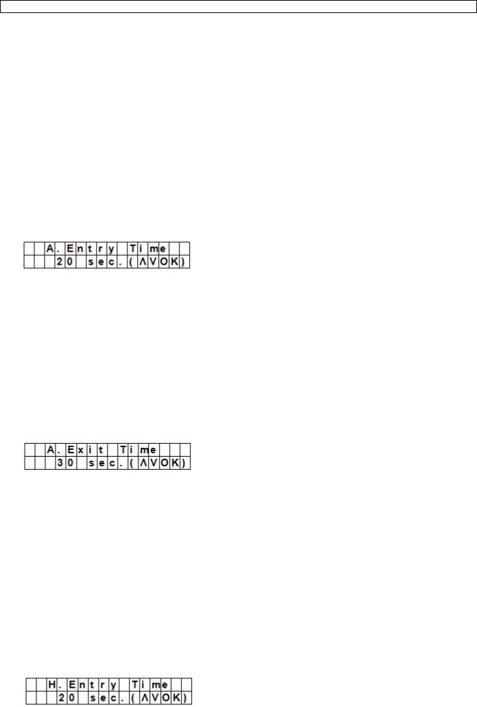
7.8A. Entry Time
The option A. Entry Time (away entry time) sets the countdown time you have to provide a pin code after entering the house.
Preconditions:
Alarm status: away
Detection devices involved: door contact or PIR sensor set as Entry or Away Entry (see section 9.3).
Action: the countdown starts when the door contact or PIR sensor is triggered.
If the pin code has not been given within the time set, the control panel will raise an alarm and send a report.
Available timer options: Disable (alarm will be raised without any delay) and delays from 10 to 70 seconds.
Factory default is 20 seconds.
To access this menu item: enter Program mode, go to Gen. Settings, select A. Entry Time and press OK.
7.9A. Exit Time
The option A. Exit Time (away exit time) sets the countdown time you have to leave the house when the alarm has been set to away by the control panel, a remote control or a remote keypad.
Preconditions:
Alarm status: set to away by the control panel, a remote control or a remote keypad
Action: the countdown starts when the alarm is set to away by the control panel, a remote control or a remote keypad.
Available timer options: Disable (no exit timer will be set) and delays from 10 to 70 seconds.
Factory default is 30 seconds.
To access this menu item: enter Program mode, go to Gen. Settings, select A. Exit Time and press OK.
Notes
Pressing the Arm button on the remote control will restart the countdown timer.
Pressing the Disarm button on the remote control will stop the counter and disarm the alarm.
Entering a pin code on the control panel will stop the counter and disarm the alarm.
7.10 H. Entry Time
V. 01 – 12/06/2013 |
12 |
©Velleman nv |

CTC1000
The option H. Entry Time (home entry time) sets the countdown time you have to enter the house when the system is set in Home mode.
Preconditions:
Alarm status: home mode
Detection devices involved: door contact or PIR sensor set as Entry or Home Access (see section 9.3).
Action: the countdown starts when the door contact or PIR sensor is triggered.
If the pin code has not been given within the time set, the control panel will raise an alarm and send a report.
Available timer options: Disable (alarm will be raised without any delay) and delays from 10 to 70 seconds.
Factory default is 20 seconds.
To access this menu item: enter Program mode, go to Gen. Settings, select H. Entry Time and press OK.
7.11 H. Exit Time
The option H. Exit Time (home exit time) sets the countdown time you have to leave the house when the system is set in Home mode.
Preconditions:
Alarm status: set to away by the control panel, remote control or remote keypad
Action: the countdown starts when the alarm is set to away by the control panel, a remote control or a remote keypad.
Available timer options: Disable (no exit timer will be set) and delays from 10 to 70 seconds.
Factory default is 30 seconds.
To access this menu item: enter Program mode, go to Gen. Settings, select H. Exit Time and press OK.
Notes
Pressing the Home button on the remote control will restart the countdown timer.
Pressing the Disarm button on the remote control will stop the counter and disarm the alarm.
Entering a pin code on the control panel will stop the counter and disarm the alarm.
7.12 Door Chime
The option Door Chime sets the door chime on or off while a door contact or PIR sensor is activated in alarm off mode.
Preconditions:
Alarm status: off
Detection devices involved: door contact or PIR sensor set as Entry or Away Entry (see section 9.3).
Action: The control panel sounds a door chime while the door contact or PIR sensor is activated in alarm off mode.
Factory default is off.
To access this menu item: enter Program mode, go to Gen. Settings, select Door Chime and press OK.
7.13 Time
The option Time allows setting the current time.
1.To access this menu item: enter Program mode, go to Gen. Settings, select Time and press OK.
2.Use the up and down arrows to set the hours and press OK.
3.Use the up and down arrows to set the minutes and press OK.
V. 01 – 12/06/2013 |
13 |
©Velleman nv |
CTC1000
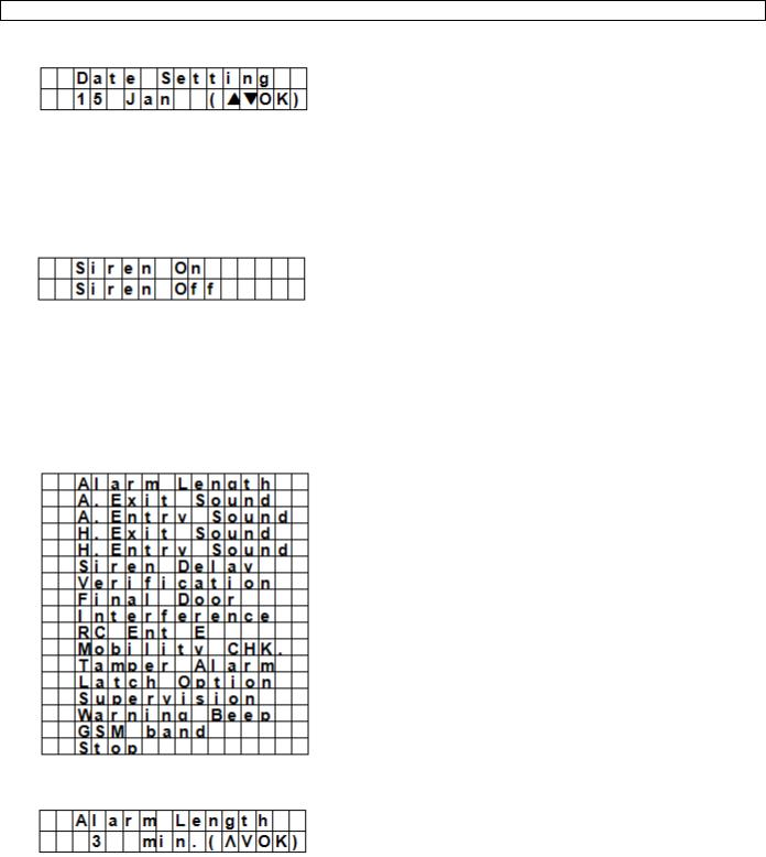
7.14 Date
The option Date allows setting the current date.
1.To access this menu item: enter Program mode, go to Gen. Settings, select Date and press OK.
2.Use the up and down arrows to set the month and press OK.
3.Use the up and down arrows to set the day and press OK.
7.15 Panel Siren
The option Panel Siren allows setting the siren on the control panel to on or off when an alarm event occurs.
1.To access this menu item: enter Program mode, go to Gen. Settings, select Panel Siren and press OK.
2.Use the up and down arrows to select the option and press OK.
8.Special Settings
To access the items from the Spc. Settings menu:
Enter Program mode and go to Spc. Settings.
Alarm Length
Sets the length of the built-in siren when an alarm is activated.
Available options are: Disable (no alarm will be set) and 1 to 15 minutes.
System default is 3 minutes.
Notes
If Disable is selected, when the control panel receives an alarm signal, the panel siren and internal & external sirens will not raise an alarm sound.
If the outdoor siren alarm length is longer than the control panel‟s, the system gives priority to the control panel. (for example when the siren‟s alarm length is set to 3 minutes and the panel‟s alarm length is set to 1 minute, both alarm siren stop at 1 minute; however, the outdoor siren‟s LED keeps flashing for 3 minutes.
V. 01 – 12/06/2013 |
14 |
©Velleman nv |

CTC1000
A. Exit Sound
(=away exit sound)
Sets the countdown beeper sounds on or off for the away exit timer.
A. Entry Sound
(=away entry sound)
Sets the countdown beeper sounds on or off for the away entry timer.
H. Exit Sound
(=home exit sound)
Sets the beeper sounds on or off when leaving the house in Home mode.
H. Entry Sound
(=home entry sound)
Sets the beeper sounds on or off when entering the house in Home mode.
Siren Delay
Sets how long the control panel should delay or suppress audible signals for burglar or entry alarms. Available options are: Off (no sound) and 1 to 10 minutes.
System default is set to off.
Notes
The Siren Delay option only applies to burglar or entry alarms. Other alarms will not be delayed: o Fire alarm
o Water alarm
o Personal panic alarm o Medical emergency o Tamper alarm
o GSM failure
The alarm reporting will be sent immediately, even if the audible alarm is delayed.
V. 01 – 12/06/2013 |
15 |
©Velleman nv |
CTC1000
Verification
Sets the verification sequence for the alarms.
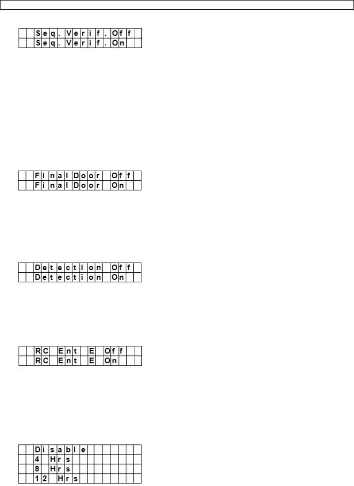
Sequential verification on
If sequential verification is set to On and
If there is more than one sensor (door contacts or PIR) with attribute set to Burglar: o If the first sensor is triggered, the control panel will send an SMS with burglar.
o If the second sensor is triggered within 30 minutes, the control panel will send an SMS with Alarm confirm.
Sequential verification off
If sequential verification is set to Off, the control panel will only send an SMS with Burglar.
Final Door
If the Final Door option is set to on and
If the alarm system is set to away arming and
a door contact is set as Entry device
The system will automatically full arm once the door contact is detected as closed, even if the countdown period is not yet finished.
Interference
Allows setting whether the control panel should detect signal jamming or not.
When Detection is set to On, whenever the signal jamming period lasted longer than 30 seconds, this error will be logged, reported to the Central Monitoring Station and displayed on the LCD to warn the user.
When the Detection Off is selected, control panel will not check interference status.
RC Ent E (= remote controller entry enabled)
This feature is used to prevent the alarm from being turned off with a remote control without unlocking a door first, for example if the remote has been stolen.
To access the function:
you need to first activate and entry point device to be able to disarm the alarm system.
If the remote controller entry is set to On:
a remote control can disarm the alarm system without unlocking a door first.
Mobility
This option disables or enables the Mobility Timer and sets a countdown period. Options available are Disable, 4 hours, 8 hours and 12 hours.
If the Mobility Timer is enabled, it will count down the pre-programmed time length. When the timer times out without being reset, a report will be made to the Programmed phone numbers.
V. 01 – 12/06/2013 |
16 |
©Velleman nv |

CTC1000
When the Mobility timer is set with a specified timer, the control panel will report to the Programmed phone numbers when the timer runs out unless one of the following actions occurred in advance to reset the timer:
o In Home mode: whenever any Home Omit DC, IR is triggered, or whenever any of the keys of the control panel is pressed;
o In Disarm mode: whenever any of the DC or IR (except 24 Hr, Fire, Medical Emergency and Water) is triggered, or whenever any of the keys of the control panel is pressed.
When the system is set to Away Arm, the timer automatically stops. When the system enters Home Arm or Disarm mode, the timer automatically starts again.
Tamper Alarm
Allows setting when the siren will sound when the system is being tampered with.
Option |
Function |
|
|
Away Arm Only |
The control panel will only raise a local alarm and send a report to the |
|
monitoring centre when in Away mode. |
|
If the alarm is in Home or Alarm off modes, the control panel will send |
|
a report but the siren will not sound. |
|
|
Normal |
The control panel will raise a local alarm and send a report to the |
|
monitoring centre in all modes. |
|
|
Notes |
Regardless of the siren setting, the panel will report the tamper alarm |
|
by SMS to the first telephone number in all modes. |
|
When tamper is restored, the panel also will report the tamper restore |
|
event by SMS to the first telephone number. |
|
|
Latch Option |
|
The Latch Option logs the arming/disarming actions from all users done on the control panel and remote control.
Notes |
If the Latchkey Reporting feature is set to Off, the feature will be |
|
hidden from the program menu (see section 7.5 Temp. Code). |
|
If the Latchkey Reporting feature is set to On, all arming/disarming |
|
actions of all users and the RCs will by default be reported to the |
|
Central Monitoring Station. |
|
For receiving the SMS-report, set the first telephone number as SMS |
|
report. |
|
|
Supervision
This option is used to enable system supervision function. When this option is set to ON, the control panel will be able to receive check-in signals from its devices to indicate their proper functioning.
Options are: Disable, 8 Hours, 12Hours, and 24Hours.
Warning Beep
V. 01 – 12/06/2013 |
17 |
©Velleman nv |

CTC1000
Sets the beep to on or off when the control panel displays an error message.
The warning beep will disappear when the error message has been read.
GSM band
Depending on service provider‟s network settings, you will need to adjust the GSM band setting accordingly.
Check with our local telecom service provider for the appropriate setting.
Stop
Select Stop and press OK key to save your settings and return to the previous menu.
9.Managing devices
The menu Devices+/- allows managing (add, configure, change, remove) devices like door contacts, PIR sensors, sirens, etc. in up to 30 zones.
Order of installation
Indoor and outdoor sirens and universal receivers are considered auxiliary devices by the system. Before adding one of these auxiliary devices, you need to add at least one other device first (a door contact, PIR detector or remote control).
9.2Add a device
To access the function:
1.Enter Program mode, go to Devices+/-, select Add device and press OK.
2.Press the test button on the device you want to add.
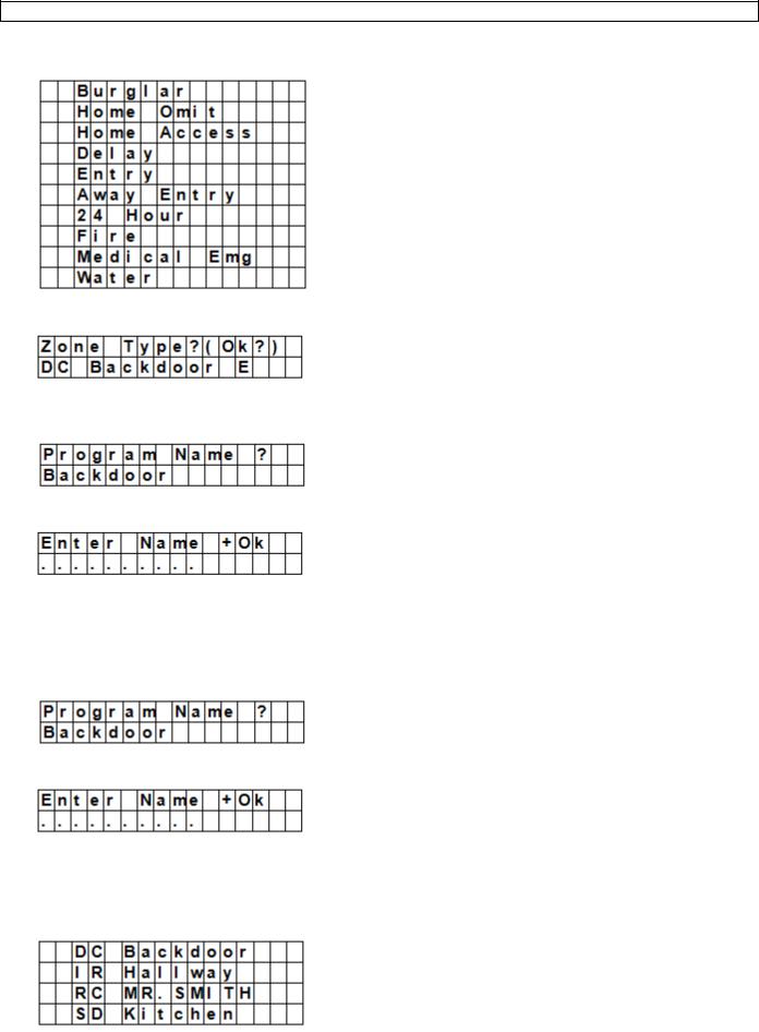
3.If the control panel detects the device, it will show the device type:
The possible devices are:
Door Contact
PIR Sensor
External PIR Sensor
Remote Controller
Remote Keypad
Water Sensor
Outdoor Siren
Universal Receiver
4. Press OK to confirm.
V. 01 – 12/06/2013 |
18 |
©Velleman nv |

CTC1000
The control panel then displays the unused defense zones (up to 30).
5.Use the arrow keys to select the zone number to which you want to assign the device and press OK. The procedure will now vary depending on the type of device you want to add.
6.Select Stop and press OK key to save your settings and return to the previous menu.
Notes
If you are trying to add a sensor that has already been added, an error message will appear.
To add this device anyway, you will need to remove it first (see section 9.5 Remove a device).
Pressing the key  cancels the procedure.
Depending on the type of device you want to add, different screens will then be displayed accordingly for further configuration purpose.
To add a door contact
1.Use the up and down arrows to select a working mode and press OK. For details about the available working modes, see section 9.3.
2.Provide a zone name.
If you do not want to use a name, leave this field blank.
3.Press OK to confirm installation.
V. 01 – 12/06/2013 |
19 |
©Velleman nv |

CTC1000
4. Press OK again to finish.
To add a PIR sensor
Assuming you have assigned a zone number (see section 9.2):
1.Use the up and down arrows to select a working mode and press OK. For details about the available working modes, see section 9.3.
2.Provide a zone name.
If you do not want to use a name, leave this field blank.
3.Press OK to confirm installation.
4.Press OK again to finish.
To add an external PIR Sensor
Assuming you have assigned a zone number (see section 9.2):
1.Use the up and down arrows to select a PIR type and press OK. o Regular: device will be added as an ordinary PIR
o External: device will be added as an external PIR.
2.Use the up and down arrows to select a working mode and press OK. For details about the available working modes, see section 9.3.
3.Provide a zone name.
If you do not want to use a name, leave this field blank. For information about entering text, see section 17.
4.Press OK to confirm installation.
5.Press OK again to finish.
To add a remote control
Assuming you have assigned a zone number (see section 9.2):
V. 01 – 12/06/2013 |
20 |
©Velleman nv |
CTC1000
1.Use the up and down arrows to select the option you want for the remote control.
o Personal att: the control panel will give a personal attack alarm when the panic button is pressed for 3 seconds or twice within 3 seconds.
o Medical Emg: the control panel will give a medical emergency alarm when the panic button is pressed for 3 seconds or twice within 3 seconds.
2.Use the up and down arrows to select a working mode and press OK. For details about the available working modes, see section 9.3.
3.Provide a zone name.
If you do not want to use a name, leave this field blank. For information about entering text, see section 17.
4.Press OK to confirm installation.
5.Press OK again to finish.
To add a remote keypad or water sensor
Installation is similar for all these device types.
Assuming you have assigned a zone number (see section 9.2):
1.Provide a zone name.
If you do not want to use a name, leave this field blank. For information about entering text, see section 17.
2.Press OK.
3.Press OK again to finish.
To add an auxiliary device (Program Siren menu)
Indoor and outdoor sirens and universal receivers are considered auxiliary devices by the system. Before adding one of these auxiliary devices, you need to add at least one other device first (detector or remote keypad). The system displays an error message if this is not the case.
1.Enter Program mode, go to Devices+/-, select Program Siren, then Learn Siren and press OK.
2.Put the device you want to add into learning mode (see this device‟s user manual).
3.Press OK.
The control panel will sound a long beep and transmit learning code to all devices simultaneously. The outdoor siren should respond by activating its siren and strobe light momentarily. The LED on the universal receiver lights up for 3 seconds.
9.3Add a device: overview of working modes
The overview below lists the possible modes for all devices taken together. The modes that are actually available depend on the type of device you are adding.
|
Mode |
System status |
Device behaviour |
|
|
|
|
|
|
|
Burglar |
When the system is in Away Arm / Home |
if a burglar door contact is triggered, a burglar |
|
|
|
Arm, or during the Entry Delay or Exit |
alarm will be activated immediately |
|
|
|
Delay period |
|
|
|
|
|
|
|
|
Home Omit |
when the system is in away arm mode |
if a home omit door contact is triggered, a |
|
|
|
(incl. away arm entry) |
burglar alarm will be activated immediately |
|
|
|
|
|
|
|
|
when the system is in home arm mode, if |
the control panel will not respond |
|
|
|
a home omit door contact is triggered |
|
|
|
|
|
|
|
|
|
during the entry delay or exit delay |
the control panel will not respond |
|
|
|
period, if a home omit door contact is |
|
|
|
|
triggered |
|
|
|
|
|
|
|
|
|
|
|
|
|
V. 01 – 12/06/2013 |
21 |
©Velleman nv |
|

CTC1000
Mode |
System status |
Device behaviour |
|
|
|
Home Access |
when the system is in away arm mode |
if a home access door contact is triggered, a |
|
|
burglar alarm will be activated immediately |
|
|
|
|
when the system is in home arm mode |
if a home access door contact is triggered, the |
|
|
control panel will start an entry delay period to |
|
|
give enough time to disarm the system |
|
|
|
|
during the entry delay or exit delay |
if a home access door contact is triggered, the |
|
period |
control panel will not respond |
|
|
|
Delay |
when the system is in away arm / home |
if a delay door contact is triggered, a burglar |
|
arm mode |
alarm will be activated immediately |
|
|
|
|
during the entry delay or exit delay |
if a delay zone door contact is triggered, the |
|
period |
control panel will not respond |
|
|
|
Entry |
when the system is in away arm / home |
if an entry door contact is triggered, the |
|
arm mode |
control panel will start an entry period to give |
|
|
enough time to disarm the system |
|
|
|
|
after the delay period is expired and no |
the control panel will respond with a burglar |
|
correct pin code is entered to disarm the |
alarm after 30 seconds |
|
system |
|
|
|
|
|
when the system is in alarm off mode |
if an entry door contact is triggered, the |
|
|
control panel will sound a door chime (if |
|
|
programmed). |
|
|
|
Away Entry |
when the system is in away arm mode |
if an away entry door contact is triggered, the |
|
|
control panel will start an entry period to give |
|
|
enough time to disarm the system |
|
|
|
|
after the delay period is expired and no |
the control panel will respond with a burglar |
|
correct pin code is entered to disarm the |
alarm after 30 seconds |
|
system |
|
|
|
|
|
when the system is in alarm off mode |
if an entry door contact is triggered, the |
|
|
control panel will sound a door chime (if |
|
|
programmed). |
|
|
|
|
when the system is in home arm mode |
if an away entry door contact is triggered, the |
|
|
control panel will not respond |
|
|
|
|
during the entry delay or exit delay |
if an away entry door contact is triggered, the |
|
period |
control panel will not respond |
|
|
|
24 Hour |
Not applicable |
the 24 hour door contact is active all the time |
|
|
and does not have to be armed or disarmed |
|
|
|
Fire |
Not applicable |
the fire door contact is active all the time and |
|
|
does not have to be armed or disarmed |
|
|
|
Medical Emg |
Not applicable |
a medical emg door contact is active all the |
|
|
time and does not have to be armed or |
|
|
disarmed |
|
|
|
Water |
Not applicable |
the water door contact is active all the time |
|
|
and does not have to be armed or disarmed |
|
|
|
9.4Edit a device
The function varies depending on the type of device you want to edit.
Edit a door contact – PIR sensor - remote control
Enter Program mode, go to Devices+/-, select Edit devices and press OK. The display lists all the devices available.
V. 01 – 12/06/2013 |
22 |
©Velleman nv |
CTC1000
1.Use the up and down arrows to select a device and press OK.
You can now change the device attribute. To skip this step, press  .
.
2.Use the up and down arrows to select an attribute and press OK.
3.Press OK to confirm.
You can now change the device name. To skip this step, press  . To continue, press OK.
4.Enter a zone name and press OK.
The display returns to the device list. Use the up and down arrows to select another device or press  .
.
Edit a remote keypad – water sensor
1.Enter Program mode, go to Devices+/-, select Edit devices and press OK. The display lists all the devices available.
2.You can now change the device name.
3.Enter a zone name and press OK.
The display returns to the device list. Use the up and down arrows to select another device or press  .
.
9.5Remove a device
1.Enter Program mode, go to Devices+/-, select Remove device and press OK. The system lists all available devices.
2.Use the up and down arrows to select a device and press OK. For details about the available working modes, see section 9.3.
V. 01 – 12/06/2013 |
23 |
©Velleman nv |

CTC1000
3. Press OK again to confirm.
9.6Program Siren menu – other options
Learn Siren
To add an outdoor bell box, indoor bell box or universal receiver… it should be programmed first by the control panel, so that the control panel can communicate with these auxiliary devices.
Before adding one of these auxiliary devices, you need to add at least one other device first (a door contact, PIR detector or remote control).
To add an outdoor or indoor siren:
1.Put the device or devices you want to add in learn mode.
2.Enter Program mode, go to Devices+/-, select Program Siren and press OK.
3.Use the up and down arrows to select Learn Siren and press OK.
o The control panel will then sound a long beep and transmit learning code to all devices simultaneously. o The outdoor siren will respond by activating its siren and strobe light momentarily.
4.Place these auxiliary devices out of Learn mode. Adding them into the system is completed.
Siren Tamp. On - Siren Tamp. Off
The outdoor siren tamper switch can be enabled and disabled remotely.
This is used especially when replacing siren battery.
To disable the siren tamper: select Siren Tamp.Off and press OK.
All added sirens will temporarity lose their tamper protection simultanously.
To enable the siren tamper: select Siren Tamp.Off and press OK. The tamper protection will be set simultaneously for all sirens.
Confirm On - Confirm Off
When set to on, the outdoor siren will sound a confirmation beep when arming or disarming the system.
When set to off, the outdoor siren will not sound a confirmation beep when arming or disarming the system.
Select Confirm On or Confirm Off and press OK.
Entry Snd On - Entry Snd Off
Enables or disables entry delay warning beeps on the siren when you enter the house. Select Entry Snd On or Entry Snd Off and press OK.
10.Other configuration functions
SMS Editor
The control panel editing the SMS message that will be sent to your mobile phone when an alarm occurs.
V. 01 – 12/06/2013 |
24 |
©Velleman nv |
CTC1000
1.Enter Program mode and select SMS Editor from the menu. The Edit Screen appears.
2.Enter an sms message (up to 16x4 characters). For information about entering text, see section 17.
3.Press OK.
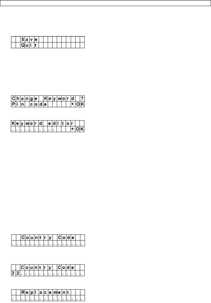
4.Select Save and press OK to confirm.
SMS Keyword
The control panel supports remote commands sent from a mobile phone to the system. Before sending remote commands, you will first need to enter a password called SMS keyword. The default keyword is the same as the default pin code (see section 7.4 Pin code).
To change the pin code for remote commands:
1.Enter Program mode, select SMS Keyword from the menu and press OK.
2.Key in a 4 digit code and press OK.
3.Repeat the code and press OK.
Country Code
The display format of the telephone number (with or without country code) may vary depending on the mobile phone provider.
If your mobile phone displays numbers without the country code, you can ignore this section.
If your mobile phone displays numbers with the country code, you need to change a setting in the control panel.
You can ask this to your provider or test it yourself as follows:
1.Insert the SIM card you will use for the control panel in a mobile phone.
2.Turn on the phone.
3.Make sure the number is not assigned to any contact on your phone.
4.Send an sms message to the same number.
o If your mobile phone displays numbers without the country code (for example 01234567890), you can ignore this section.
o If your mobile phone displays numbers with the country code (for example +321234567890), proceed as follows.
5.On the control panel, enter Program mode, go to Country Code and press OK.
6.Enter the country code of your country.
Example: if the number displayed on your phone was +321234567890, type 32 (without the „+‟).
7.Press OK.
8.In the Replacement screen, key in 0.
V. 01 – 12/06/2013 |
25 |
©Velleman nv |
CTC1000
9. Press OK to finish.
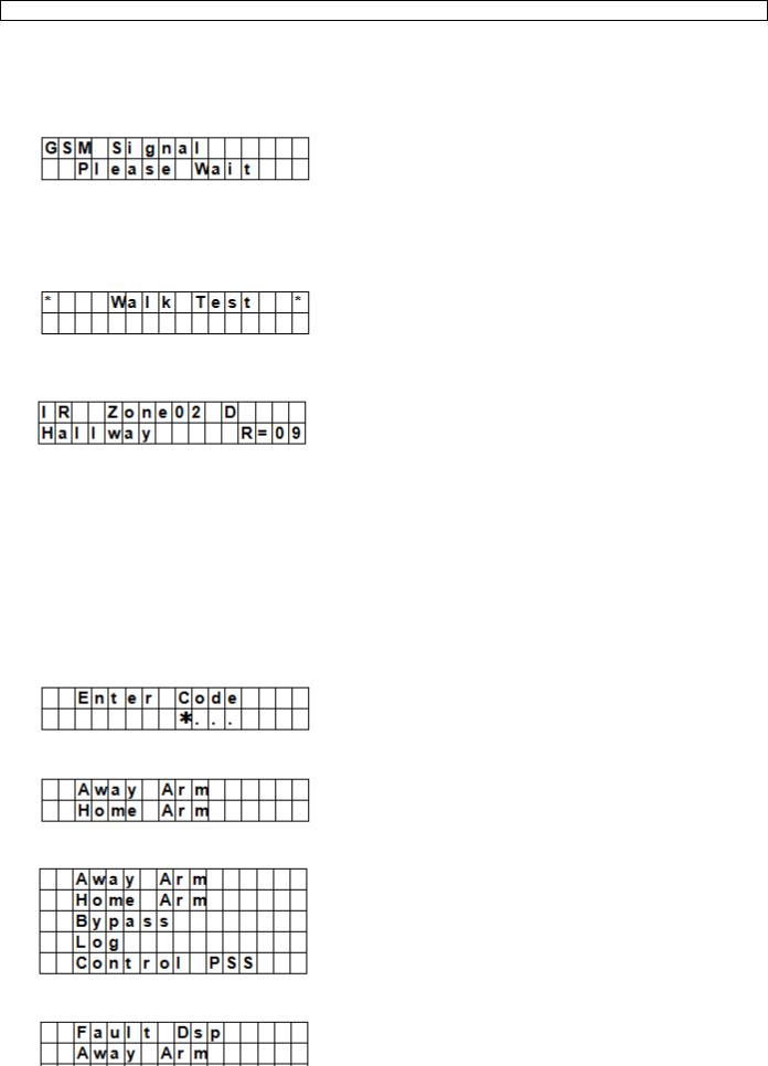
GSM Signal
The option GSM signal allows monitoring the signal strength.
1. On the control panel, enter Program mode, go to GSM signal and press OK.
The system will display the signal strength (from 0 to 9, 9 being the strongest signal).
Walk Test
The option Walk Test checks the communication between the control panel and any device.
1.On the control panel, enter Program mode, go to Walk Test and press OK.
2.Press the Test button on the device you want to test.
If the control panel receives a signal, it will display the device‟s name, zone and signal strength.
3.Press  to exit.
Reset GSM
The option Reset GSM resets the mobile phone signal.
1.On the control panel, enter Program mode, go to Reset GSM and press OK. The signal takes about 1 minute to reset.
11.Using the alarm
When the alarm is disarmed (off), enter a pin code to access the user menu. From this menu, you can set the alarm on or off.
Enter the first digit of your pin code.
1.Within 10 seconds, enter the other digits of the pin code. The display shows:
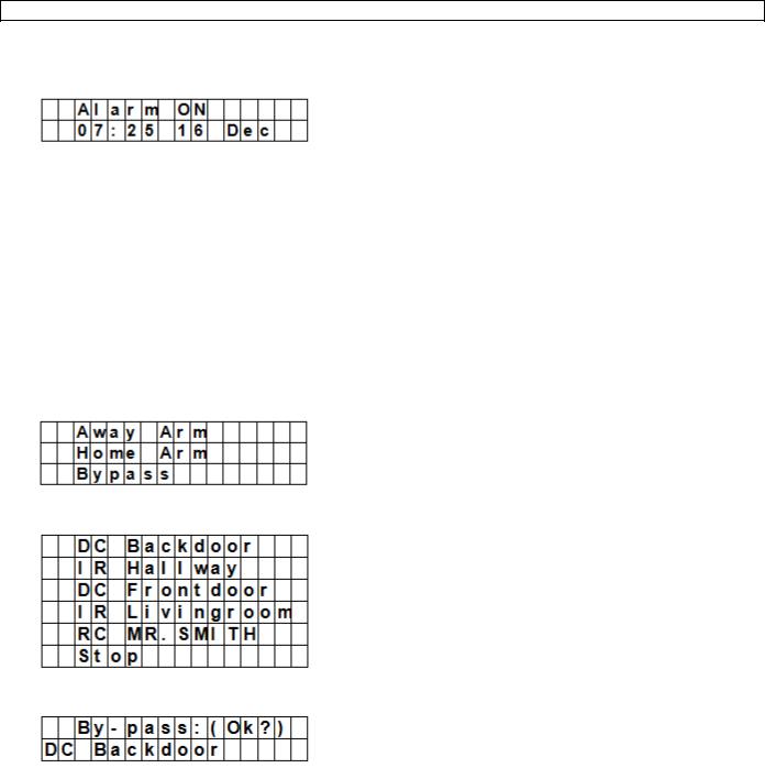
2.The cursor blinks next to Away Arm. The full menu contains the following items:
If the system has detected an error, the first line of the display will show:
11.2 Arming the system
If the system is disarmed, you can arm it as follows:
V. 01 – 12/06/2013 |
26 |
©Velleman nv |

CTC1000
1.Enter your pin code and press OK. The display shows:
2.The cursor blinks next to Away Arm. Press OK. The display shows:
o The control panel starts the countdown and plays a sound.
(The sound and actual exit time depend on your settings, see 7.9.)
o When the countdown time is up, the system will play a long sound and the system will be armed.
Notes
The control panel has a screen saver function. The Alarm ON message will be displayed for 180 seconds. After that, the display shows only current date and time.
If the Final Door Set Option is set to ON, the control panel will enter Alarm On mode as soon as the door has been closed.
If a door contact or PIR sensor has been triggered (for example a door is still open), you cannot arm the system. To arm the system anyway, see section Force arming the system below.
The system can also be armed with the (optional) remote control.
Stopping the exit delay
When you have armed the system and the countdown timer is still running, the exit delay can be stopped by disarming the system.
1.Press  key.
key.
The screen will ask you to enter the pin code.
The counting down delay is displayed on the control panel.
2.Enter your pin code and press OK.
Alarm Off will be displayed on the screen and the system returns to Disarmed mode.
o The exit delay can also be stopped by pressing the Disarm button on the (optional) remote control. o If the exit delay period times out before the code can be entered, the system will be armed.
Extending the exit delay (remote control only)
During the exit delay period, the delay time can be extended by pressing the Arm button on the (optional) remote control.
Press and hold the Arm button for 1 second and you will hear a long beep to confirm the extension of exit time.
Every time you press the Arm button on the remote, the delay time starts counting from the beginning.
11.3 Force arming the system
If you are entering your pin code while the system has detected an error, the control panel displays an error message.
If you then select Away Arm and press OK, the control panel will play a warning sound indicating arming is prohibited. The display will then alternatively display the actual errors and the message Fault Dsp.
You will need to press  key to return back to Alarm Off Screen. If an error occurs, you can
solve the problems and clear the error display (see section 14) and arm the system (recommended).
ignore the errors and arm the system despite the errors, as follows:
In the Fault Dsp screen:
1. Enter your pin code and press OK. The display shows:
V. 01 – 12/06/2013 |
27 |
©Velleman nv |

CTC1000
2.Press OK to confirm.
o The control panel starts the countdown and plays a sound.
(The sound and actual exit time depend on your settings, see 7.9.)
o When the countdown time is up, the system will play a long sound and the system will be armed.
Arming with door opened
While you arm the system, if any door was detected to be open, the control panel will also sound a warning to indicate arming is prohibited. The message Fault DSP is displayed in the middle of the top display row and alternates at 2-second intervals with the sensor name that is being triggered.
At this moment, you can close the opened door, after which the error display will be cleared automatically and the screen returns to Alarm off. You can the arm the system.
If you want to put the system into Arm mode with the door opened, you can use Forced Arming.
Notes
The Fault DSP screen has a time-out for 5 minutes. It will automatically exit and return to Alarm Off screen after 5 minutes.
If a sensor is by-passed (see section Partial Arm mode), the condition of that sensor will not be checked.
If a sensor tampered or out-of-order occurs, you can temporarily by-pass it or permanently remove it.
11.4 Disarming the system
You can disarm the system if it is either in Away Arm mode or Home Arm mode (Alarm ON):
1. Enter your pin code and press OK. The control panel will sound 2 short beeps and return to disarmed mode.
Remote control
When the system is in Home mode (see below), pressing the Disarm button on the remote control will disarm the system.
When the system is in Away Arm mode, pressing the Disarm button on the remote control can disarm the system when either an Entry device has been triggered, or when the Remote Controller Entry Enable has been set to ON (see section RC Ent E (= remote controller entry enabled) in chapter 8).
11.5 Home Arm mode
The Home mode allows the home to be armed so that no one can get inside without first disarming the system, yet the person already inside the house can move freely without triggering the alarm.
You can only enter the Home Arm mode when the system is disarmed. To activate Home mode:
1.Enter your pin code and press OK.
2.Press key to move the cursor down to select Home Arm and press OK.
V. 01 – 12/06/2013 |
28 |
©Velleman nv |
CTC1000
oThe control panel starts the countdown and plays a sound.
(The sound and actual exit time depend on your settings, see 7.9.)
o When the countdown time is up, the system will play a long sound and the system will be armed.
Notes
The system can also be armed with the (optional) remote control
To stop the exit delay, see section Stopping the exit delay in chapter 11.2.
To extend the exit delay, see Extending the exit delay (remote control only) in chapter 11.2.
If the system has detected an error and you want to arm the system anyway, see section 11.3 Force arming the system.
11.6 Partial arm mode (by-pass mode)
The Partial Arm mode allows the user to de-activate (by-pass) any sensors at their discretion. This feature allows your home to be armed; yet the person inside the house can move freely in the area where the sensor is by-passed.
To activate Partial arm mode:
1.Enter your pin code and press OK.
2.Press key to move the cursor down to select Bypass and press OK.
3.Press & keys to select the zone to be by-passed and press OK (for example: DC backdoor).
4.Press OK to confirm.
The bypassed zone will be marked with a *.
5.Repeat steps 2-4 to by-pass another device.
6.When done, press  key to return to user menu and the cursor stays at Arm.
7.Press OK.
Notes
If a sensor is by-passed, the control panel will not respond to its triggering in Arm mode.
The by-pass setting is effective for only one time, once the system is disarmed, the by-pass setting is cleared automatically.
When a sensor is by-passed, the system can be armed directly regardless of its error situation (if any). However, its situation is still being monitored and will be logged and displayed when you access the Log submenu.
11.7 Stopping an alarm
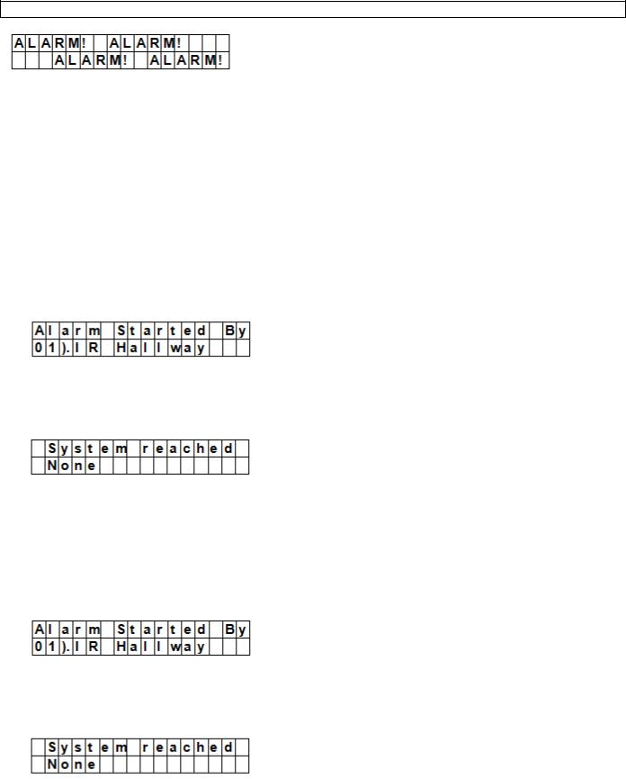
During any alarm, the control panel will sound its siren and report to the programmed mobile phone number. The display shows:
V. 01 – 12/06/2013 |
29 |
©Velleman nv |
CTC1000
During an alarm, to stop the siren and clear the display:
Key in your pin code and press OK.
If the pin code is correct, the alarm sounding will be stopped.
If you press any key other than the first digit of your pin code, the screen will prompt you to enter your pin code.
Reporting
The reporting behaviour varies depending on when you stop the alarm
Before reporting has started
While reporting is on-going
After reporting was finished
Alarm stopped before reporting has started
The system will not send any alarm reports.
1.The display will show the device that triggered the alarm with its zone number.
2.Press OK.
If multiple alarms have been raised, the control panel continues displaying the 2nd alarm event with 02). at the beginning of the 2nd line.
3.Repeat pressing OK until the display shows:
[meaning: system did not reach any phone numbers]
4.Press OK.
The display returns to Alarm off. Or press  to review all events.
Alarm stopped while reporting is on-going
1.The display will show the device that triggered the alarm with its zone number.
2.Press OK.
If multiple alarms have been raised, the control panel continues displaying the 2nd alarm event with 02). at the beginning of the 2nd line.
3.Repeat pressing OK until the display shows:
[meaning: system did not reach any phone numbers]
4.Press OK.
The display returns to Alarm off.
Alarm stopped after reporting was finished
1. The display will show the device that triggered the alarm with its zone number.
V. 01 – 12/06/2013 |
30 |
©Velleman nv |
Loading...