


Altivar31
Table of contents
 Loading...
Altivar 31
####
####
####
CANopen
User’s manual
11/2009
1624599
www.schneider-electric.com

Table of Contents
Although every care has been taken in the preparation of this document, Schneider
Electric SA cannot guarantee the contents and cannot be held responsible for any
errors it may contain nor for any damage wich may result from its use or application.
The products and options described in this document may be changed or modified at
any time, either from a technical point of view or in the way they are operated. Their
desciption can in no way be considered contractual.
Foreword ___________________________________________________________________________________________________ 3
Hardware setup______________________________________________________________________________________________ 4
Configuration ______________________________________________________________________________________________ 10
Signalling__________________________________________________________________________________________________ 11
Software setup _____________________________________________________________________________________________ 12
Software setup with PL7 and SyCon ___________________________________________________________________________ 15
Description of the services ___________________________________________________________________________________ 24
Object dictionary ___________________________________________________________________________________________ 37
2 1624599 11/2009

Foreword
Structure of the documentation:
• The present user’s manual describes the use of the CANopen interface of the Altivar 31.
• For general hardware setting up refer to the "Installing manual".
• For complete description of the functions, parameters and variables refer to the "Programming manual"
• The user’s manual "Communication variables" describes:
- the drive behaviour (state charts, modes of operation, ...)
- the attributes of the parameters and variables (address, unit, code, name, description, ...).
The present user’s manual describes the "Heartbeat" service of Altivar 31. This service is available only with version V1.2 and
above.
1624599 11/2009 3

Hardware setup
Altivar 31
RUN
ESC
ENT
STOP
RESET
RUN
ERR
CAN
1
2
4
3
5
7
6
Description of the ATV 31 front panel
Legend:
ATV 31pppppA front view
1 Red LED indicates the DC bus is under voltage when lit (“
z” symbol)
2 A 4-digit “7-segment” display
3 Central programming terminal (the reference potentiometer is only present
on ATV 31
4 “RUN” key, used to start the motor in forward mode (ATV 31
pppppA)
pppppA only)
5 “STOP/RESET” key, used to stop the motor and to reset the current faults
(ATV 31
pppppA only)
6 This front panel lock requires the use of a crossed or flat screwdriver in order
to lock/unlock the front panel of the drive
7 These two LEDs, included in the 4-digit display of the drive, are used to
signal the communication state (“
RUN”) and the presence of any fault (“ERR”)
on the CANopen bus
4 1624599 11/2009
Hardware setup
####
####
####
####
CANopen
TSX CPP 110
PowerSuite
CANopen
trunk cable
CANopen
trunk cable
ATV 31 CANopen tap
VW3 CAN TAP 2
ATV 31 drop cord
VW3 CAN CA RR
p
Master PLC
+ TSX CPP 110
Modbus
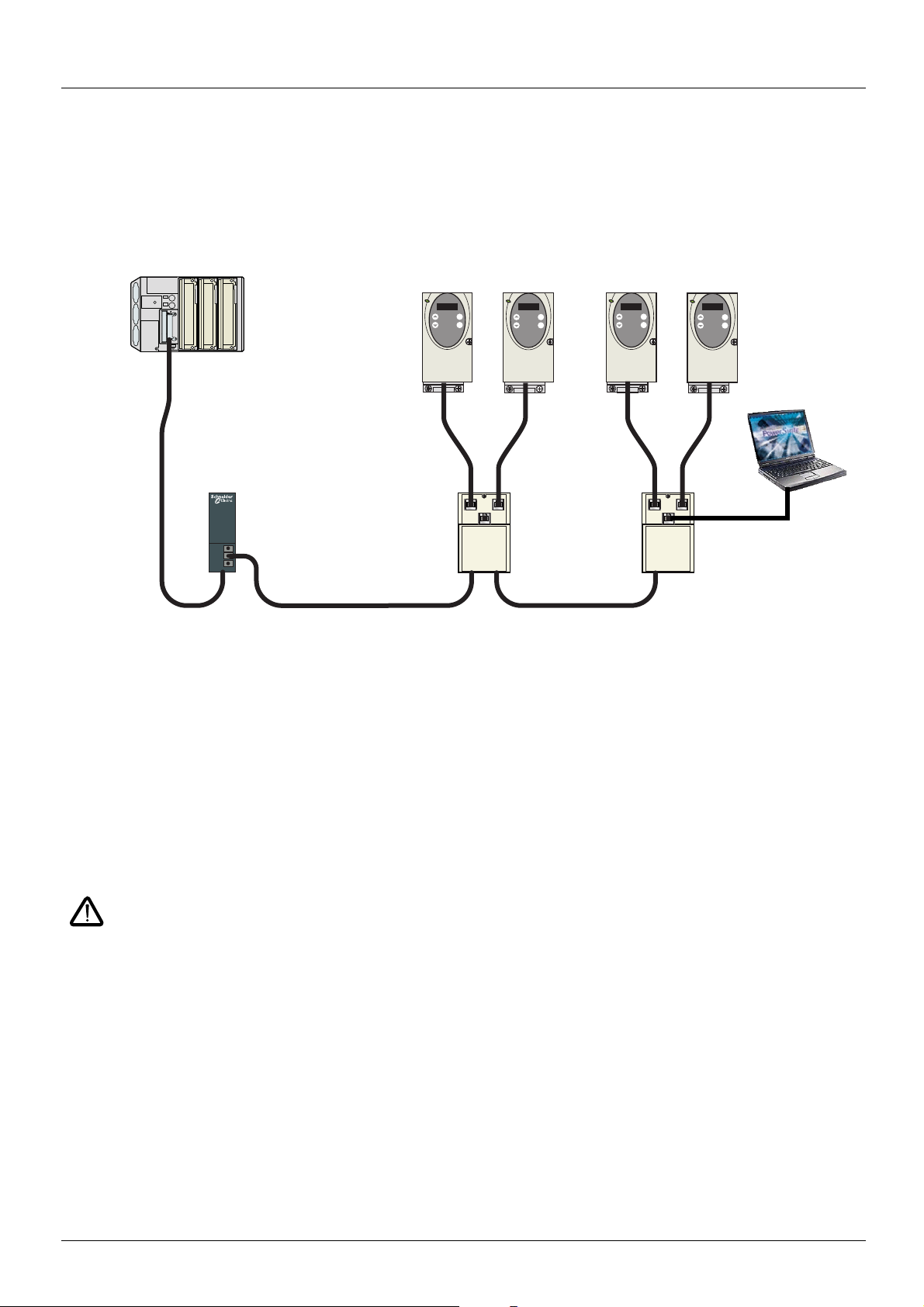
Example of CANopen configuration
The following diagram shows an example of four ATV 31, connected to a master PLC Premium with a CANopen master PCMCIA card (TSX
CPP 110).
Various accessories are available from the catalogue to realise connection of devices.
ATV 31 CANopen tap is a passive tap (reference: VW3 CAN TAP 2)
It can be connected on a CANopen trunk cable, using the two 5-screw terminals embedded connectors.
Two RJ45 connectors allow the connection of two Altivar 31 by ATV 31 CANopen drop cords.
One RJ45 connector is designed to interface these two Altivar 31 with PowerSuite (Commissioning software tool for PC or Pocket PC).
If only one ATV 31 is connected on the tap it should be on the connector labelled "ATV1".
If two ATV 31 are connected, PowerSuite can access the two drives in multidrop mode. The Modbus address of each drive must be different.
A remote terminal (VW3 A31101) can also be connected to the "PowerSuite" connector, but in this case, only one ATV 31 drive can be
connected to the CANopen tap (on the plug labelled "ATV1").
ATV 31 CANopen drop cord is a cable equipped with 2 RJ45 connectors. Two lengths are available: 0.3 m (reference: VW3 CAN CA RR 03)
and 1 m (reference: VW3 CAN CA RR1).
Only a 0.3 m drop cord can be used in a CANopen network at a speed of 1 Mbits/s.
1624599 11/2009 5

Hardware setup
1
ATV1 ATV2
PowerSuite
S1 S2
S3
ON
S4 S5
OFF
23
4
2
4
7
9
8
10
3
5
7
6
9
8
11
10
Description of the ATV 31 CANopen tap (VW3 CAN TAP 2)
External view Internal view
Legend:
1 Cover fixing screw.
2 “ATV1” female RJ45 connector where the first Altivar 31 drive must be connected.
3 “ATV2” female RJ45 connector where the second, (if any), Altivar 31 drive must be connected. Do not use if a remote terminal is
connected to the "PowerSuite" connector.
4 “PowerSuite” female RJ45 connector, where PowerSuite (PC or Pocket PC) or a remote terminal can be connected.
5 Switch used to connect (
6 Lug for connecting the green/yellow grounding wire.
7 CANopen terminal blocks, labelled S4 and S5 on the circuit board for wiring of the trunk cable.
8 Holes for Ø 4 screws used to mount the tap on a plate or panel (60 mm mounting distance).
9 Ground plate for the trunk cable shield.
10 Openings for the CANopen trunk cable.
11 Opening for the green/yellow grounding wire.
ON) or disconnect (OFF) the internal line termination (120 Ω).
6 1624599 11/2009
Hardware setup
ATV1
ATV2
Power
Suite
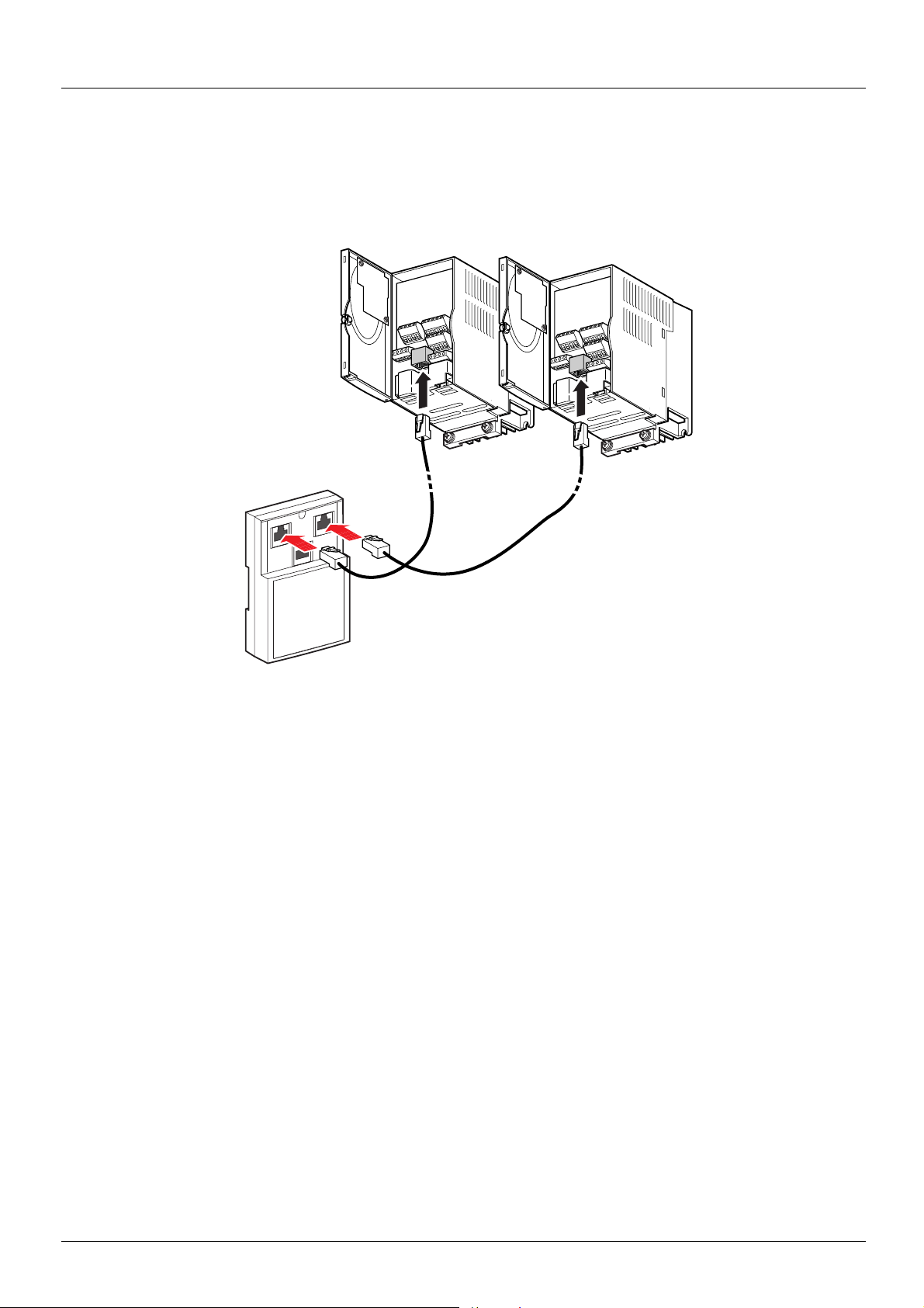
Connecting the drive to the ATV 31 CANopen tap
Connect the cord with 2 RJ45 connectors (VW3 CAN CA RR 03 or VW3 CAN CA RR 1) to the RJ45 connector of the drive and to the “ATV1”
or “ATV2” female RJ45 connector located on the ATV 31 CANopen tap (VW3 CAN TAP 2).
If only one Altivar 31 is connected to the ATV 31 CANopen tap the “ATV1” connector must be used.
1624599 11/2009 7
Hardware setup
20
19
22
23
21
7
6
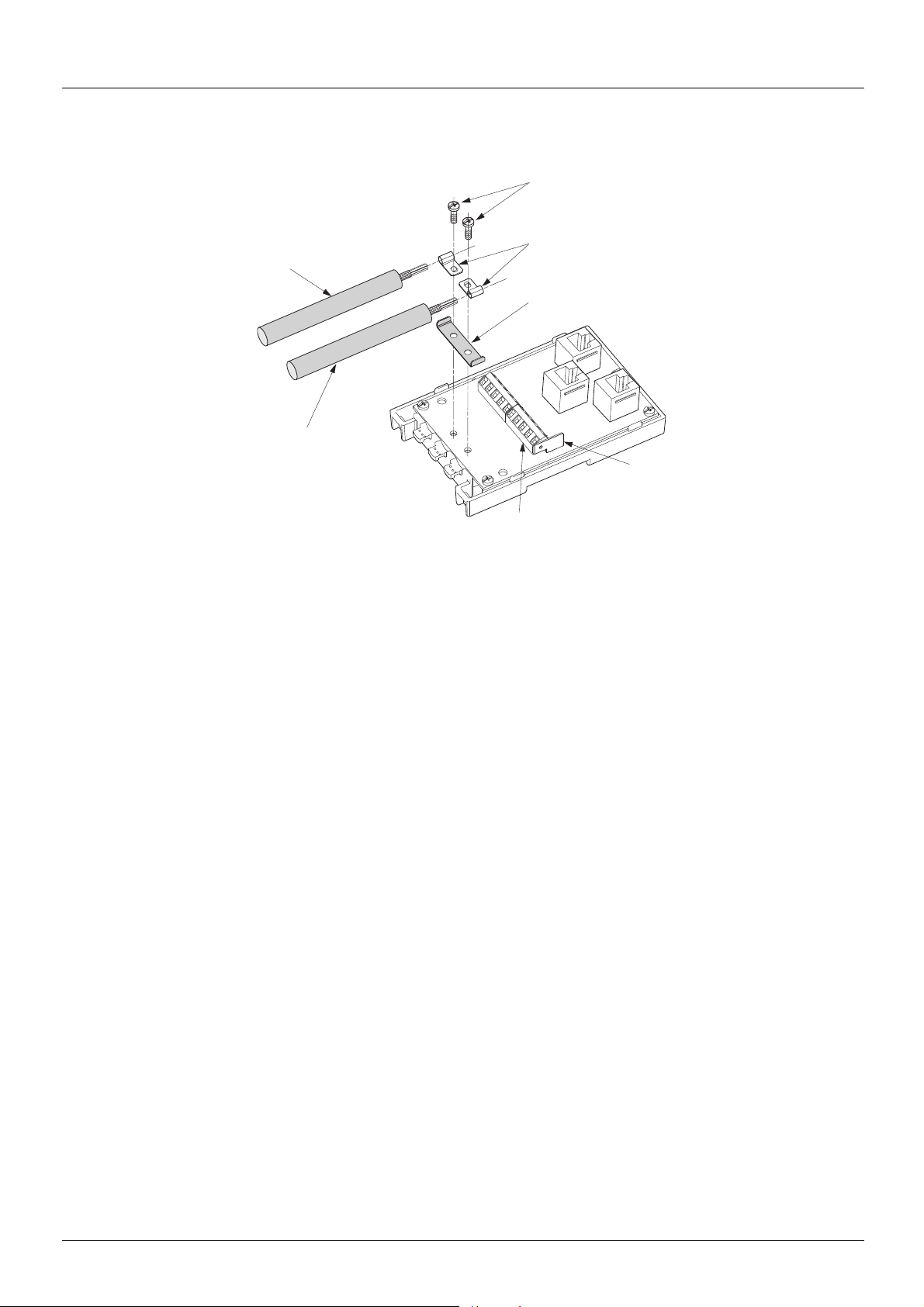
Setup of the CANopen tap
Tools required:
• 2.5 mm flat screwdriver.
• PZ01 cross recess screwdriver.
Procedure:
Note: the numbers shown below correspond to the numbers in the tap description.
• Unscrew screw 1 using a PZ01 screwdriver. Open cover.
• Fix the tap base to its support:
- either to an AM1-DP200 or AM1-DE 200 DIN rail
- or to a plate or panel using 2 M4 screws at least 20 mm long
• Prepare trunk cables 20 and 21, as shown on the following pages.
• Position grounding clamps 22 on the cables.
• Position ground connection 23.
• Connect the trunk cables to terminal blocks 7, as shown on the following pages.
Use a 2.5 mm flat screwdriver.
Thread torque on terminal block screw
• Screw down the grounding clamps and connections using screws 19 and a cross recess screwdriver (PZ01).
• Connect the green/yellow grounding wire to the connection lug 6.
• Immobilise the cables using nylon clamps.
• Position micro-switch to ON if line termination is required and to OFF if not.
• Break the tabs on the cover so that the cables can pass through.
y 0.25 N.m.
• Replace cover and fix it in place with screw 1 using a cross recess screwdriver (PZ01).
8 1624599 11/2009

Hardware setup
8 mm 8 mm
54 mm
Shielding
S1 S2
S3
ON
S4 S5
OFF
1234
5
GND
CAN_L
SHLD
CAN_H
(V+)
8........................1
Connecting the trunk cable
Cable preparation guide
Pin Signal Wire colour Description
1 GND Black Ground
2 CAN_L Blue CAN_L bus line
3 SHLD (bare cableshield) Optional shield
4 CAN_H White CAN_H bus line
5 (V+) Red Optional supply (1)
(1)If the CANopen cables have a fourth (red) wire, it should be connected to pin 5 in order to relay the V+
optional signal to the other CANopen stations.
Pin out of the RJ45 connectors
Pin Signal Pin Signal Pin Signal
(2)Modbus signals
(3)Supply for RS232 / RS485 converter or a remote terminal
1 CAN_H 1 CAN_H 1 Not connected
2 CAN_L 2 CAN_L 2 Not connected
3 CAN_GND 3 CAN_GND 3 Not connected
4 D1 (2) 4 D1 (2) 4 D1 (2)
5 D0 (2) 5 D0 (2) 5 D0 (2)
6 Not connected 6 Not connected 6 Not connected
7 VP (3) 7 Not connected 7 VP (3)
8 Common (2) 8 Common (2) 8 Common (2)
ATV1 ATV2 PowerSuite
1624599 11/2009 9

Configuration
Configuration of the CANopen communication functions of the Altivar 31 can be accessed from the Communication menu /98! .
The configuration can only be modified when the motor is stopped and the drive is locked.
Any change will only be applied after a power cycle of the drive (power off then power on).
Parameter Possible values Terminal display Default value
CANopen Address
-@/#
CANopen Speed
>@/#
The -@/# parameter will thereafter be referred to as “Node-ID” in the present User’s Manual.
The default value (0) of this parameter disables the CANopen communications of the Altivar 31.
In order to enable CANopen on the Altivar 31, you must set a non-zero value for -@/#.
The value of the >@/# parameter must match the communication speed of all the other devices connected to the CANopen bus.
In addition, the maximum length of the bus depends on the communication speed. The following table specifies the maximum bus length
when an Altivar 31 is placed on a CANopen bus, depending on the actual communication speed:
0 to 127 # to $%* 0
0,010 kbits/s
20 kbits/s
50 kbits/s
125 kbits/s
250 kbits/s
500 kbits/s
1,000 kbits/s
0$#.#
#%#.#
#(#.#
$%(.#
%(#.#
(##.#
$###
125 kbits/s
Communication speed 10 kbits/s 20 kbits/s 50 kbits/s 125 kbits/s 250 kbits/s 500 kbits/s 1,000 kbits/s
Maximum length of the bus 5,000 m 2,500 m 1,000 m 500 m 250 m 100 m 5 m
Some other documents specify greater lengths, they only apply to CANopen devices without galvanic insulation.
Due to galvanic insulation of the CANopen interface of ATV 31, the lengths mentioned in the table above must be respected .
At the speed of 1,000 kbits/s, the lenght of the drops must be limited to 0.3 m.
10 1624599 11/2009
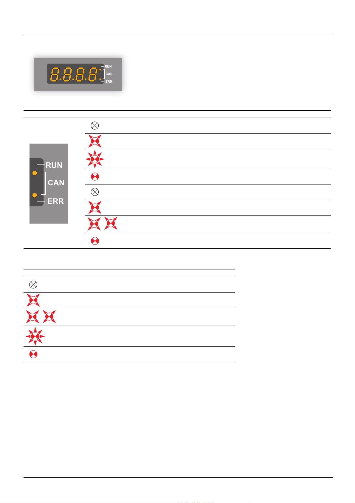
Signalling
The two signalling LEDs located immediately on the right of the 4-digit 7-segment front
display unit of the Altivar 31 are used to indicate the status of the CANopen
communications.
LED state Altivar 31 / CANopen state
The CANopen controller is in “OFF” state
The Altivar 31 is in “S
The Altivar 31 is in “P
The Altivar 31 is in “O
No error reported
Warning reported by the CANopen controller of the Altivar 31 (e.g. too many error frames)
Error due to the occurrence of a node-guarding event or a heartbeat event
The CANopen controller is in “bus-off” state
Description of the various LED states:
LED state Visual description of the LED state
The LED is OFF
The LED is SINGLE FLASHING
(200 ms ON and 1 second OFF)
The LED is DOUBLE FLASHING
(200 ms ON, 200 ms OFF, 200 ms ON, and 1 second OFF)
TOPPED” state
RE-OPERATIONAL” state
PERATIONAL” state
The LED is BLINKING at 2.5 Hz
(200 ms ON and 200 ms OFF)
The LED is ON
1624599 11/2009 11

Software setup
Profiles
Communication profile
The communication profile of Altivar 31 is based on:
• CAN 2.A;
• The CANopen specification (DS301 V4.02).
Simplified structure of the telegram:
Identifier (11 bits) User data (maximum length of 8 bytes)
COB-ID Byte 0 Byte 1 Byte 2 Byte 3 Byte 4 Byte 5 Byte 6 Byte 7
For more information, log on the Can In Automation Web site: http://www.can-cia.de
Functional profile
The functional profile of the Altivar 31 complies with:
• “Device profile for drives and motion control” (DSP-402 V2.0, Velocity Mode);
• Drivecom profile (21).
Drivecom and CANopen DSP402 are compatible.
.
12 1624599 11/2009
Loading...