


MBRS320T3

© Semiconductor Components Industries, LLC, 2008
November, 2008 − Rev. 9
1 Publication Order Number:
MBRS340T3/D
MBRS320T3, MBRS330T3,
MBRS340T3
Surface Mount
Schottky Power Rectifier
These devices employ the Schottky Barrier principle in a large area
metal−to−silicon power diode. State−of−the−art geometry features
epitaxial construction with oxide passivation and metal overlay
contact. Ideally suited for low voltage, high frequency rectification, or
as free wheeling and polarity protection diodes, in surface mount
applications where compact size and weight are critical to the system.
Features
• Small Compact Surface Mountable Package with J−Bend Leads
• Rectangular Package for Automated Handling
• Highly Stable Oxide Passivated Junction
• Very Low Forward Voltage Drop
(0.5 V Max @ 3.0 A, T
J
= 25°C)
• Excellent Ability to Withstand Reverse Avalanche Energy Transients
• Guard−Ring for Stress Protection
• Device Passes ISO 7637 Pulse #1
• Pb−Free Packages are Available
Mechanical Characteristics
• Case: Epoxy, Molded, Epoxy Meets UL 94 V−0
• Weight: 217 mg (Approximately)
• Finish: All External Surfaces Corrosion Resistant and Terminal
Leads are Readily Solderable
• Lead and Mounting Surface Temperature for Soldering Purposes:
260°C Max. for 10 Seconds
• Polarity: Notch in Plastic Body Indicates Cathode Lead
• Device Meets MSL 1 Requirements
• ESD Ratings: Machine Model, C > 400 V
Human Body Model, 3B > 8000 V
Device Package Shipping
†
ORDERING INFORMATION
SMC
CASE 403
PLASTIC
MBRS320T3 SMC 2500/Tape & Reel
SCHOTTKY BARRIER
RECTIFIERS
3.0 AMPERES
20, 30, 40 VOLTS
MBRS320T3G SMC
(Pb−Free)
2500/Tape & Reel
MBRS330T3 SMC 2500/Tape & Reel
MARKING DIAGRAM
B3x = Device Code
x = 2, 3 or 4
A = Assembly Location
Y = Year
WW = Work Week
G = Pb−Free Package
(Note: Microdot may be in either location)
http://onsemi.com
†For information on tape and reel specifications,
including part orientation and tape sizes, please
refer to our Tape and Reel Packaging Specification
Brochure, BRD8011/D.
MBRS330T3G SMC
(Pb−Free)
2500/Tape & Reel
MBRS340T3 SMC 2500/Tape & Reel
MBRS340T3G SMC
(Pb−Free)
2500/Tape & Reel
AYWW
B3xG
G
MBRS320T3, MBRS330T3, MBRS340T3
http://onsemi.com
2
MAXIMUM RATINGS
Rating Symbol MBRS320T3 MBRS330T3 MBRS340T3 Unit
Peak Repetitive Reverse Voltage
Working Peak Reverse Voltage
DC Blocking Voltage
V
RRM
V
RWM
V
R
20 30 40 V
Average Rectified Forward Current I
F(AV)
3.0 @ T
L
= 110°C
4.0 @ T
L
= 105°C
A
Nonrepetitive Peak Surge Current
(Surge applied at rated load conditions halfwave,
single phase, 60 Hz)
I
FSM
80 A
Operating Junction Temperature T
J
− 65 to +150 °C
ISO 7637 Pulse #1
(100 V, 10W)
5000 Pulses
ESD Ratings: Machine Model = C
ESD Ratings: Human Body Model = 3B
>400
>8000
V
Stresses exceeding Maximum Ratings may damage the device. Maximum Ratings are stress ratings only. Functional operation above the
Recommended Operating Conditions is not implied. Extended exposure to stresses above the Recommended Operating Conditions may affect
device reliability.
THERMAL CHARACTERISTICS
Thermal Resistance, Junction−to−Lead
R
q
JL
11 °C/W
ELECTRICAL CHARACTERISTICS
Maximum Instantaneous Forward Voltage (Note 1)
(i
F
= 3.0 A, T
J
= 25°C)
V
F
0.50
V
Maximum Instantaneous Reverse Current (Note 1)
(Rated dc Voltage, T
J
= 25°C)
(Rated dc Voltage, T
J
= 100°C)
i
R
2.0
20
mA
1. Pulse Test: Pulse Width = 300 ms, Duty Cycle ≤ 2.0%.
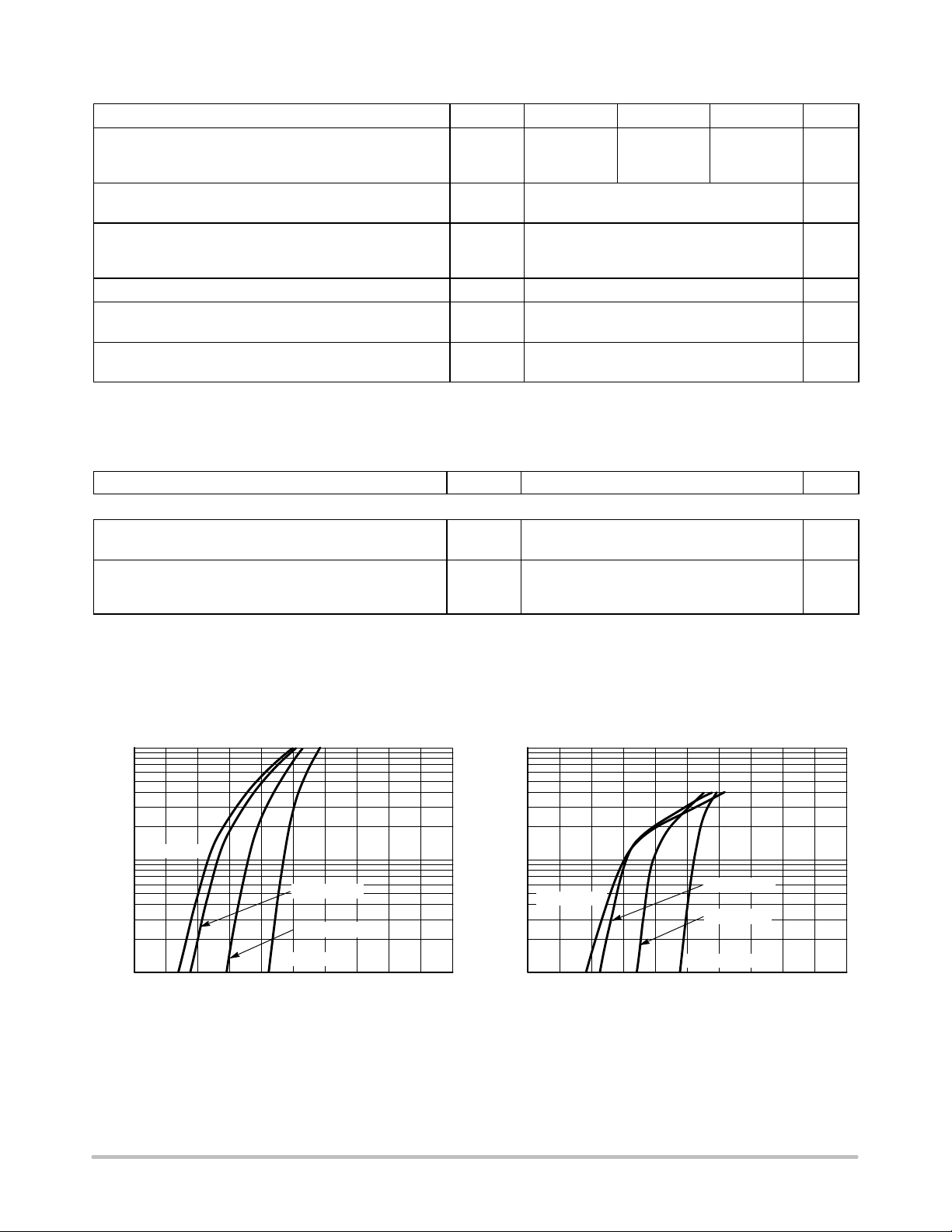
TYPICAL ELECTRICAL CHARACTERISTICS
10
0.1
0.20.0 0.4 0.6
V
F
, INSTANTANEOUS FORWARD VOLTAGE (V)
Figure 1. Typical Forward Voltage Figure 2. Maximum Forward Voltage
1
0.8
I
F
, FORWARD CURRENT (AMPS)
T
J
= 25°C
T
J
= 125°C
T
J
= 100°C
T
J
= −65°C
V
F
, MAXIMUM INSTANTANEOUS FORWARD VOLTAGE (V)
I
F
, FORWARD CURRENT (AMPS)
1.00.30.1 0.5 0.7 0.9
10
0.1
0.20.0 0.4 0.6
1
0.8
T
J
= 25°C
T
J
= 125°C
T
J
= 100°C
T
J
= −65°C
0.30.1 0.5 0.7 0.9 1.0
 Loading...