


NordicTrack E7 sv User Manual

www.nordictrack.com
Model No. NTEL07808.0
Serial No.
Write the serial number in the
space above for reference.
@_-%( (oSeuriadeNrU_dbeerfDeamle)
"=='=1_ ....
E7
Ff_rlt E_fiv_
USER'S MANUAL
QUESTIONS?
As a manufacturer, we are commit-
ted to providing complete customer
satisfaction. If you have questions,
or if parts are damaged or missing,
DO NOT CONTACT THE STORE;
please contact Customer Care.
IMPORTANT: You must note the
product model number and serial
number (see the drawing above)
before contacting us:
CALL TOLL-FREE:
1-888-825-2588
Mon.-Fri. 6 a.m.-6 p.m. MT
Sat. 8 a.m.-4 p.m. MT
ON THE WEB:
www.nordictrackservice.com
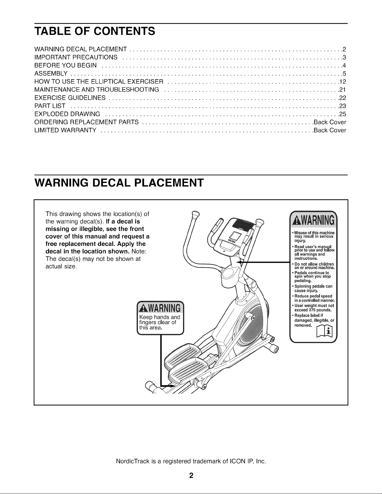
TABLE OF CONTENTS
WARNING DECAL PLACEMENT .............................................................. 2
IMPORTANT PRECAUTIONS ................................................................ 3
BEFORE YOU BEGIN ...................................................................... 4
ASSEMBLY ............................................................................... 5
HOW TO USE THE ELLIPTICAL EXERCISER .................................................. 12
MAINTENANCE AND TROUBLESHOOTING ................................................... 21
EXERCISE GUIDELINES ................................................................... 22
PART LIST .............................................................................. 23
EXPLODED DRAWING .................................................................... 25
ORDERING REPLACEMENT PARTS .................................................. Back Cover
LIMITED WARRANTY .............................................................. Back Cover
WARNING DECAL PLACEMENT
This drawing shows the location(s) of
the warning decal(s). If a decal is
missing or illegible, see the front
cover of this manual and request a
free replacement decal. Apply the
decal in the location shown. Note:
The decal(s) may not be shown at
actual size.
•Misuse ofthis machine
may result in serious
injury.
• Read user's manual
priorto use and follow
all warnings and
instructions.
• Do not allow children
onor around machine.
• Pedals continue to
spin when you stop
pedaling,
• Spinning pedals can
cause injury.
• Reduce pedal speed
in a controlled manner.
User weight must not
exceed 275 pounds.
• Replace label if
damaged, illegible, or
removed, [_
NordicTrack is a registered trademark of ICON IP, Inc.
2
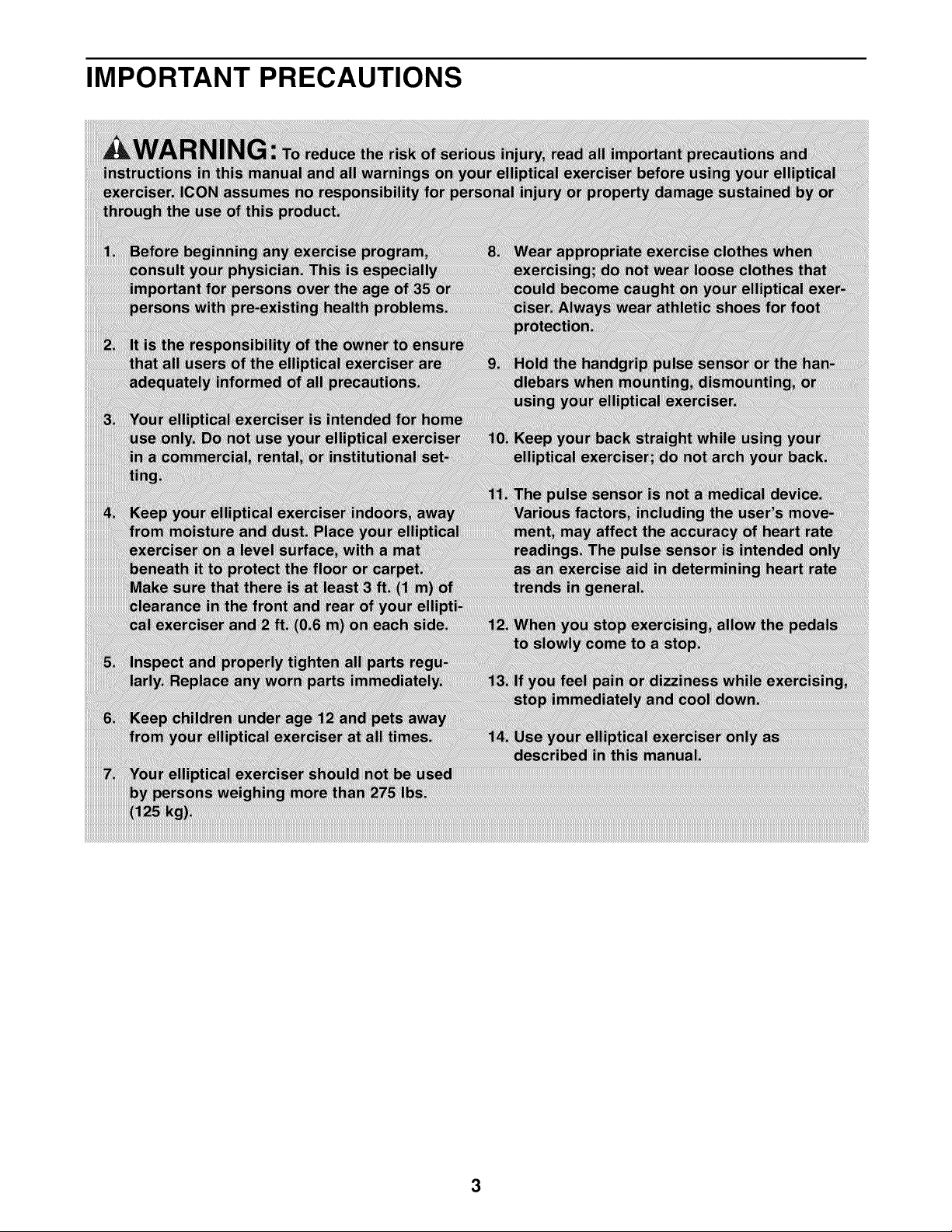
IMPORTANT PRECAUTIONS
3

BEFORE YOU BEGIN
Thank you for selecting the new NordicTrack ®E7 SV
FRONT DRIVE elliptical exerciser. The E7 SV FRONT
DRIVE elliptical exerciser provides a wide array of fea-
tures designed to make your workouts at home more
effective and enjoyable.
For your benefit, read this manual carefully before
you use the elliptical exerciser. If you have ques-
tions after reading this manual, please see the front
Console
Water Bottle Holder*
cover of this manual. To help us assist you, note the
product model number and serial number before con-
tacting us. The model number and the location of the
serial number decal are shown on the front cover of
this manual.
Before reading further, please familiarize yourself with
the parts that are labeled in the drawing below.
Handgrip Pulse Sensor
Handlebar
Ramp Handle
Pedal
Ramp
Handle
Wheel
Roller
*Water bottle is not included
4
ASSEMBLY
Assembly requires two persons. Place all parts of the elliptical exerciser in a cleared area and remove the
packing materials. Do not dispose of the packing materials until assembly is completed.
In addition to the included tool(s), assembly requires a Phillips screwdriver _====_, two adjustable
wrenches _, and a rubber mallet _.
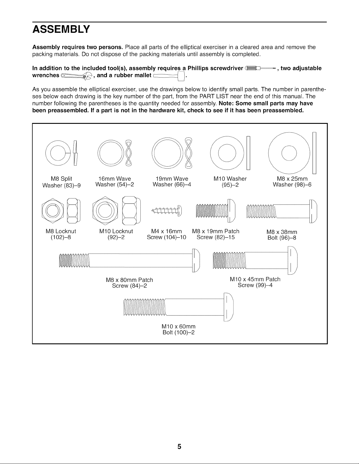
As you assemble the elliptical exerciser, use the drawings below to identify small parts. The number in parenthe-
ses below each drawing is the key number of the part, from the PART LIST near the end of this manual. The
number following the parentheses is the quantity needed for assembly. Note: Some small parts may have
been preassembled. If a part is not in the hardware kit, check to see if it has been preassembled.
M8 Split
Washer (83)-9 Washer (54)-2
M8 Locknut
(1O2)-8
16mm Wave
M10 Locknut
(92)-2
M8 x 80mm Patch
Screw (84)-2
19mm Wave
Washer (66)-4
M4 x 16mm
Screw (104)-10
M10 x 60mm
Bolt (100)-2
M10 Washer
(95)-2
M8 x 19mm Patch
Screw (82)-15
MIO x 45mm Patch
H
Screw (99)-4
1
M8 x 25mm
Washer (98)-6
M8 x 38mm
Bolt (96)-8
5
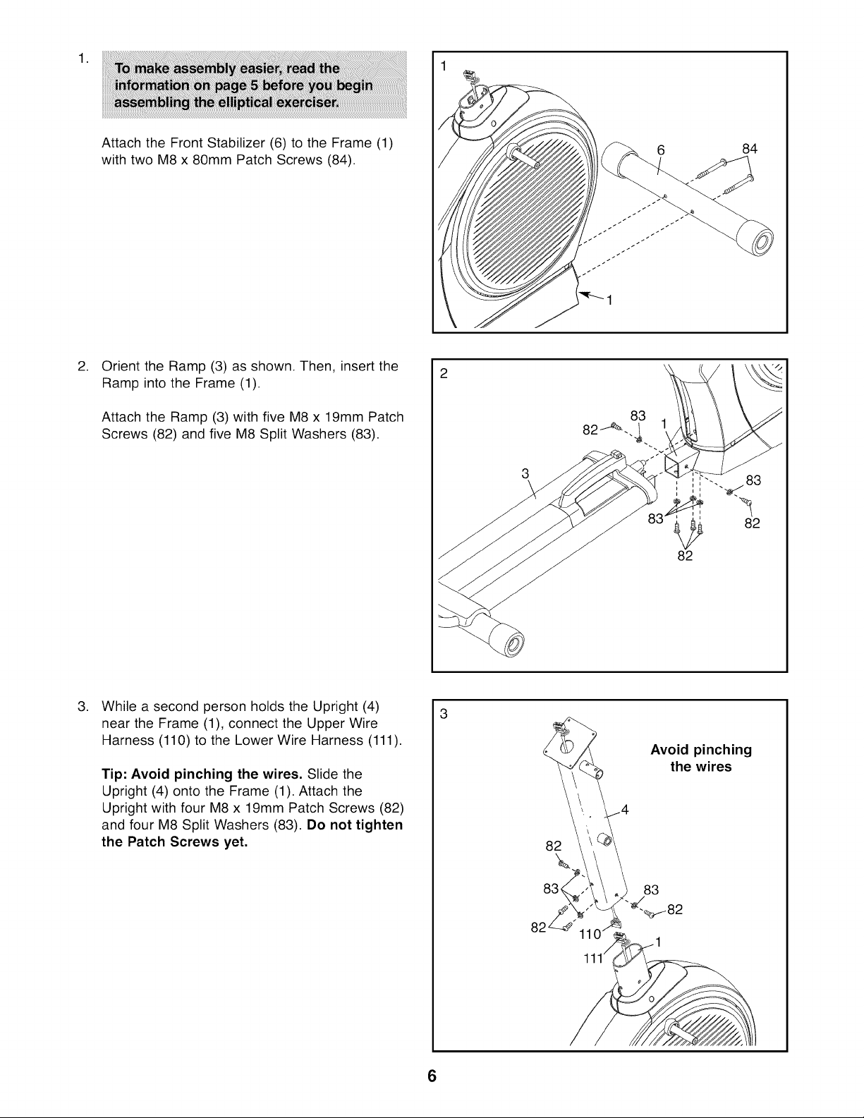
.
Attach the Front Stabilizer (6) to the Frame (1)
with two M8 x 80mm Patch Screws (84).
.
Orient the Ramp (3) as shown. Then, insert the
Ramp into the Frame (1).
Attach the Ramp (3) with five M8 x 19mm Patch
Screws (82) and five M8 Split Washers (83).
84
82
.
While a second person holds the Upright (4)
near the Frame (1), connect the Upper Wire
Harness (110) to the Lower Wire Harness (111).
Tip: Avoid pinching the wires. Slide the
Upright (4) onto the Frame (1). Attach the
Upright with four M8 x 19mm Patch Screws (82)
and four M8 Split Washers (83). Do not tighten
the Patch Screws yet.
82
Avoid pinching
the wires
83
6
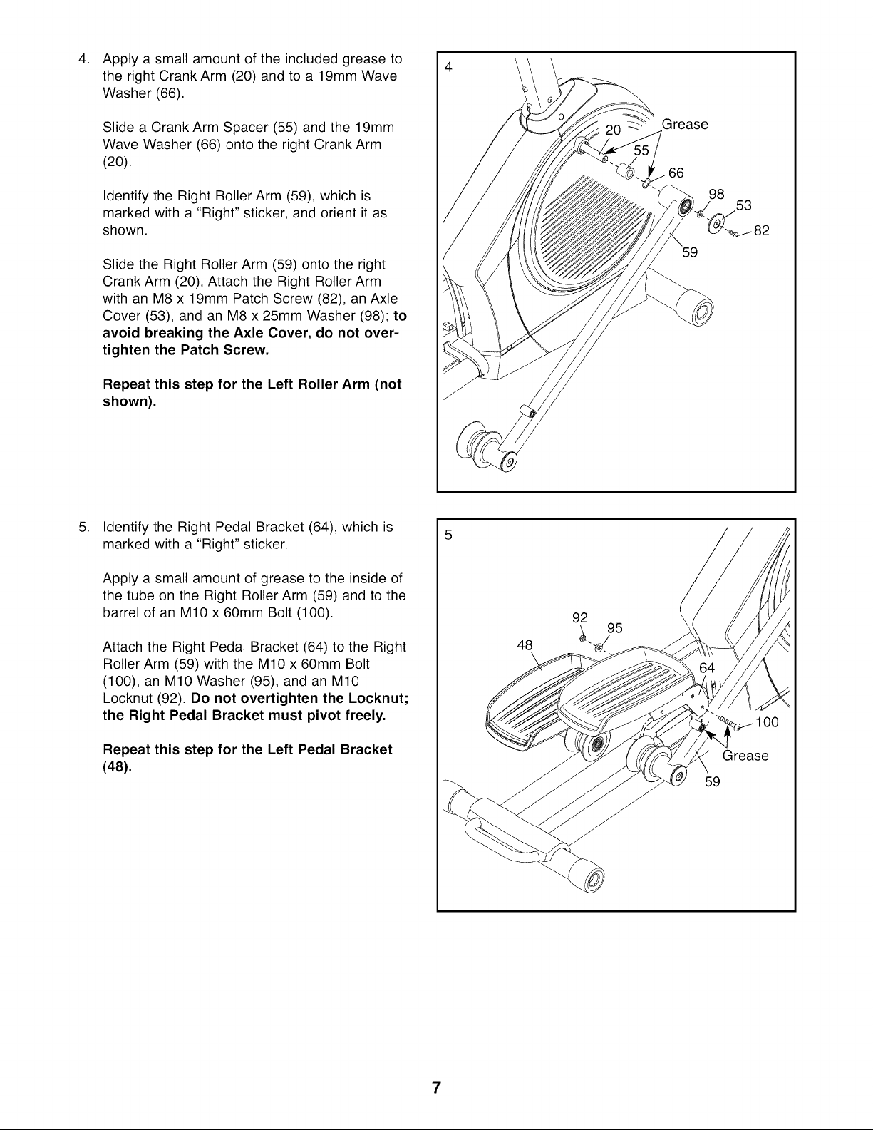
Apply a small amount of the included grease to
the right Crank Arm (20) and to a 19mm Wave
Washer (66).
Slide a Crank Arm Spacer (55) and the 19mm
Wave Washer (66) onto the right Crank Arm
(20).
Identify the Right Roller Arm (59), which is
marked with a "Right" sticker, and orient it as
shown.
Slide the Right Roller Arm (59) onto the right
Crank Arm (20). Attach the Right Roller Arm
with an M8 x 19mm Patch Screw (82), an Axle
Cover (53), and an M8 x 25mm Washer (98); to
avoid breaking the Axle Cover, do not over-
tighten the Patch Screw.
Repeat this step for the Left Roller Arm (not
shown).
.
Identify the Right Pedal Bracket (64), which is
marked with a "Right" sticker.
Grease
98
53
59
Apply a small amount of grease to the inside of
the tube on the Right Roller Arm (59) and to the
barrel of an M10 x 60mm Bolt (100).
Attach the Right Pedal Bracket (64) to the Right
Roller Arm (59) with the M10 x 60mm Bolt
(100), an M10 Washer (95), and an M10
Locknut (92). Do not overtighten the Locknut;
the Right Pedal Bracket must pivot freely.
Repeat this step for the Left Pedal Bracket
(48).
92
48
\
100
Grease
59
7
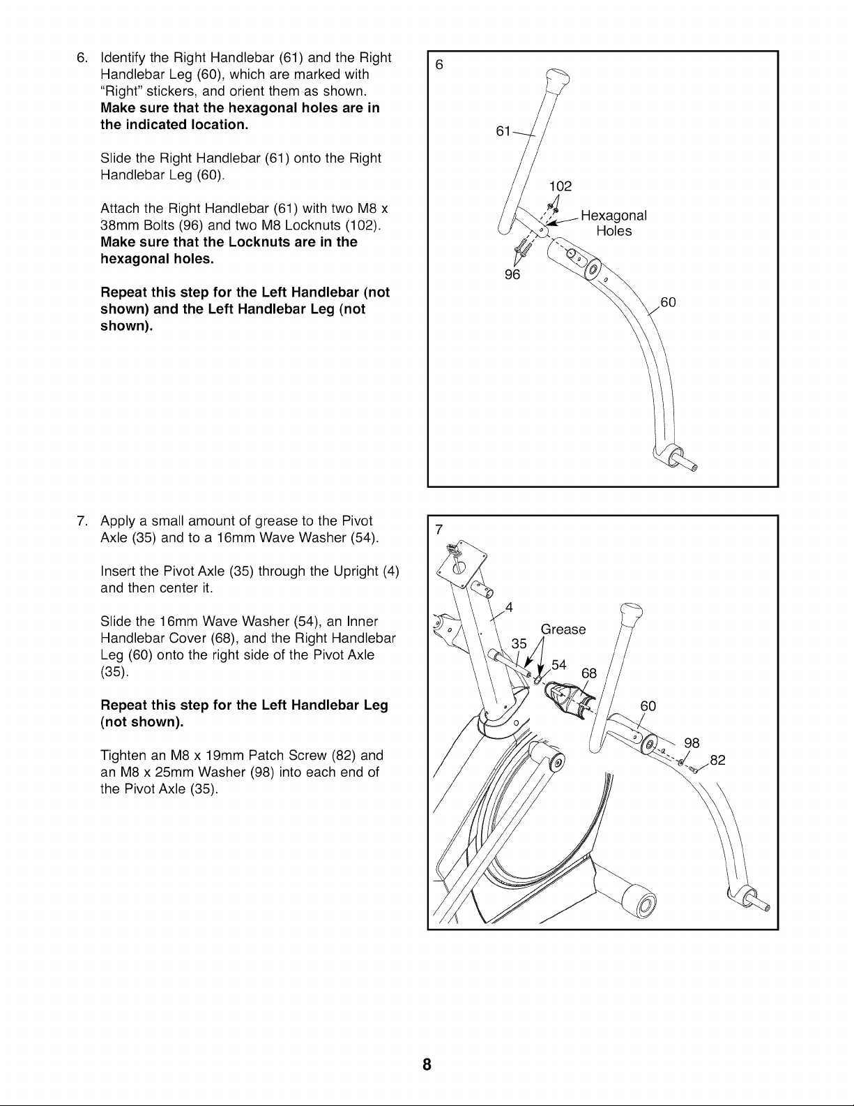
Identify the Right Handlebar (61) and the Right
6. 6
Handlebar Leg (60), which are marked with
"Right" stickers, and orient them as shown.
Make sure that the hexagonal holes are in
the indicated location.
Slide the Right Handlebar (61) onto the Right
Handlebar Leg (60).
Attach the Right Handlebar (61) with two M8 x
38mm Bolts (96) and two M8 Locknuts (102).
Make sure that the Locknuts are in the
hexagonal holes.
Repeat this step for the Left Handlebar (not
shown) and the Left Handlebar Leg (not
shown).
61
102
Hexagonal
Holes
96
60
.
Apply a small amount of grease to the Pivot
Axle (35) and to a 16mm Wave Washer (54).
Insert the Pivot Axle (35) through the Upright (4)
and then center it.
Slide the 16mm Wave Washer (54), an Inner
Handlebar Cover (68), and the Right Handlebar
Leg (60) onto the right side of the Pivot Axle
(35).
Repeat this step for the Left Handlebar Leg
(not shown).
Tighten an M8 x 19mm Patch Screw (82) and
an M8 x 25mm Washer (98) into each end of
the Pivot Axle (35).
7
Grease
68
60
98
8

Attach an Outer Handlebar Cover (67) and the
8. 8
Inner Handlebar Cover (68) around the Right
Handlebar Leg (60) with two M4 x 16mm
Screws (104).
Repeat this step for the other side of the
elliptical exerciser.
.
Apply a small amount of grease to the axle on
the Right Handlebar Leg (60) and to a 19mm
Wave Washer (66).
Identify the Right Pedal Arm (58), which is
marked with a "Right" sticker, and orient it as
shown.
60
67
68
Slide the 19mm Wave Washer (66) and the
Right Pedal Arm (58) onto the Right Handlebar
Leg (60).
Attach the Right Pedal Arm (58) with an M8 x
19mm Patch Screw (82), an Axle Cover (53),
and an M8 x 25mm Washer (98); to avoid
breaking the Axle Cover, do not overtighten
the Patch Screw.
Repeat this step for the Left Pedal Arm (not
shown).
Grease
8 53
82
58
9
 Loading...