


NordicTrack NEL12940 Owner's Manual
Model No. NEL1294.0
www.nordictrack.com
Visit our website at
w
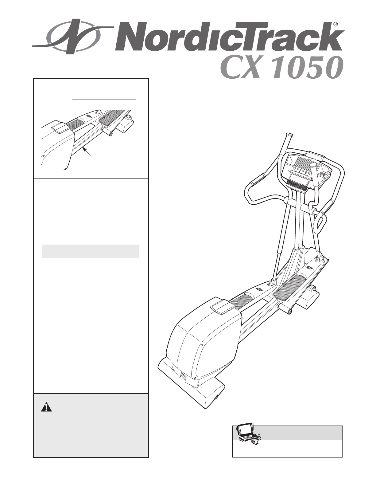
Serial No. _
Serial Number
Decal
QUESTIONS?
As a manufacturer, we are committed to providing complete
customer satisfaction. If you
have questions, or if there are
missing parts, please call:
1-888-936-4266
USERʼS MANUAL
Mon.–Fri. 8h00 until 17h00 EST
(excluding holidays).
CAUTION
Read all precautions and instructions in this manual before using
this equipment. Keep this manual
for future reference.

TABLE OF CONTENTS
IMPORTANT PRECAUTIONS . . . . . . . . . . . . . . . . . . . . . . . . . . . . . . . . . . . . . . . . . . . . . . . . . . . . . . . . . . . . . . . .3
BEFORE YOU BEGIN . . . . . . . . . . . . . . . . . . . . . . . . . . . . . . . . . . . . . . . . . . . . . . . . . . . . . . . . . . . . . . . . . . . . . .4
ASSEMBLY . . . . . . . . . . . . . . . . . . . . . . . . . . . . . . . . . . . . . . . . . . . . . . . . . . . . . . . . . . . . . . . . . . . . . . . . . . . . . . .5
HOW TO USE THE CHEST PULSE SENSOR . . . . . . . . . . . . . . . . . . . . . . . . . . . . . . . . . . . . . . . . . . . . . . . . . . .9
HOW TO USE THE ELLIPTICAL EXERCISER . . . . . . . . . . . . . . . . . . . . . . . . . . . . . . . . . . . . . . . . . . . . . . . . . .11
MAINTENANCE AND TROUBLESHOOTING . . . . . . . . . . . . . . . . . . . . . . . . . . . . . . . . . . . . . . . . . . . . . . . . . . .25
CONDITIONING GUIDELINES . . . . . . . . . . . . . . . . . . . . . . . . . . . . . . . . . . . . . . . . . . . . . . . . . . . . . . . . . . . . . . .26
PART LIST . . . . . . . . . . . . . . . . . . . . . . . . . . . . . . . . . . . . . . . . . . . . . . . . . . . . . . . . . . . . . . . . . . . . . . . . . . . . . .28
EXPLODED DRAWING . . . . . . . . . . . . . . . . . . . . . . . . . . . . . . . . . . . . . . . . . . . . . . . . . . . . . . . . . . . . . . . . . . . .30
HOW TO ORDER REPLACEMENT PARTS . . . . . . . . . . . . . . . . . . . . . . . . . . . . . . . . . . . . . . . . . . . . .Back Cover
LIMITED WARRANTY . . . . . . . . . . . . . . . . . . . . . . . . . . . . . . . . . . . . . . . . . . . . . . . . . . . . . . . . . . . . . .Back Cover
NordicTrack is a registered trademark of ICON IP, Inc.
2
IMPORTANT PRECAUTIONS
WARNING: T
tions before using the elliptical exerciser.
1. Read all instructions in this manual and all
warnings on the elliptical exerciser before
using the elliptical exerciser.
2. It is the responsibility of the owner to ensure
that all users of the elliptical exerciser are
adequately informed of all precautions.
3. The elliptical exerciser is intended for
in-home use only. Do not use the elliptical
exerciser in a commercial, rental, or institutional setting.
4. Keep the elliptical exerciser indoors, away
from moisture and dust. Place the elliptical
exerciser on a level surface, with a mat
beneath it to protect the floor or carpet.
Make sure that there is enough clearance
around the elliptical exerciser to mount, dismount, and use it.
5. Inspect and properly tighten all parts regularly. Replace any worn parts immediately.
6. Keep children under age 12 and pets away
from the elliptical exerciser at all times.
o reduce the risk of serious injury, read the following important precau-
11. If you feel pain or dizziness while exercising, stop immediately and cool down.
12. The pulse sensors are not medical devices.
Various factors, including the user's movement, may affect the accuracy of heart rate
readings. The pulse sensors are intended
only as exercise aids in determining heart
rate trends in general.
13. When you stop exercising, allow the pedals
to slowly come to a complete stop. The elliptical exerciser does not have a free wheel;
the pedals will continue to move until the
flywheel stops.
14. Always unplug the power cord immediately
after use and before cleaning the elliptical
exerciser.
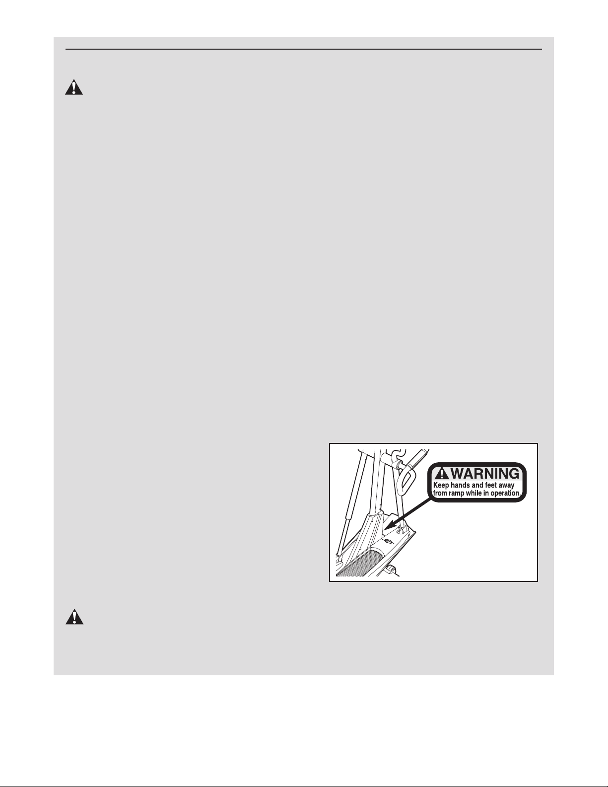
15. The decal shown below has been placed on
the elliptical exerciser. If the decal is missing or illegible, call the toll-free telephone
number on the front cover of this manual
and order a free replacement decal. Apply
the decal in the location shown.
7. The elliptical exerciser should not be used
by persons weighing more than 115 kg (250
lbs.).
8. Wear appropriate exercise clothing when
using the elliptical exerciser. Always wear
athletic shoes for foot protection.
9. Always hold the handlebars when mounting,
dismounting, or using the elliptical exerciser.
10. Keep your back straight when using the elliptical exerciser; do not arch your back.
WARNING: Before beginning this or any exercise program, consult your physician.
This is especially important for persons over the age of 35 or persons with pre-existing health problems. Read all instructions before using. ICON assumes no responsibility for personal injury or
property damage sustained by or through the use of this product.
3
BEFORE YOU BEGIN
Thank you for choosing the new NordicTrack®CX
1050 elliptical exerciser. The unique CX 1050 elliptical
xerciser offers an impressive selection of features
e
designed to make your workouts at home more effective and enjoyable. And the CX 1050 moves your feet
in a natural elliptical path, minimizing the impact on
your knees and ankles.
For your benefit, read this manual carefully before
you use the elliptical exerciser. If you have ques-
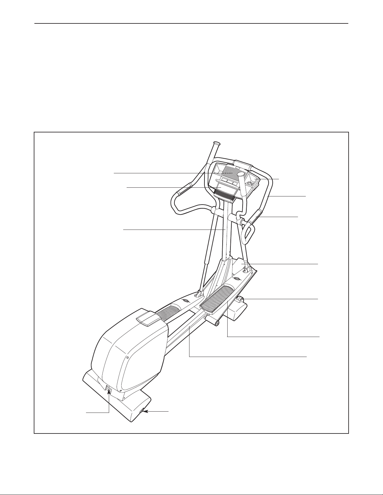
Fan
Console
Upright
tions after reading the manual, please see the front
cover of this manual. To help us assist you, please
ote the product model number and serial number
n
before contacting us. The model number is
NEL1294.0. The serial number can be found on a
decal attached to the elliptical exerciser (see the front
cover of this manual for the location of the decal).
Before reading further, please familiarize yourself with
the parts that are labeled in the drawing below.
Water Bottle Holder*
Handlebar
Pulse Sensor
BACK
Power Socket
Leveling Foot
FRONT
Ramp
Wheel
Pedal
Pedal Leg
RIGHT SIDE
*No water bottle is included
4
ASSEMBLY
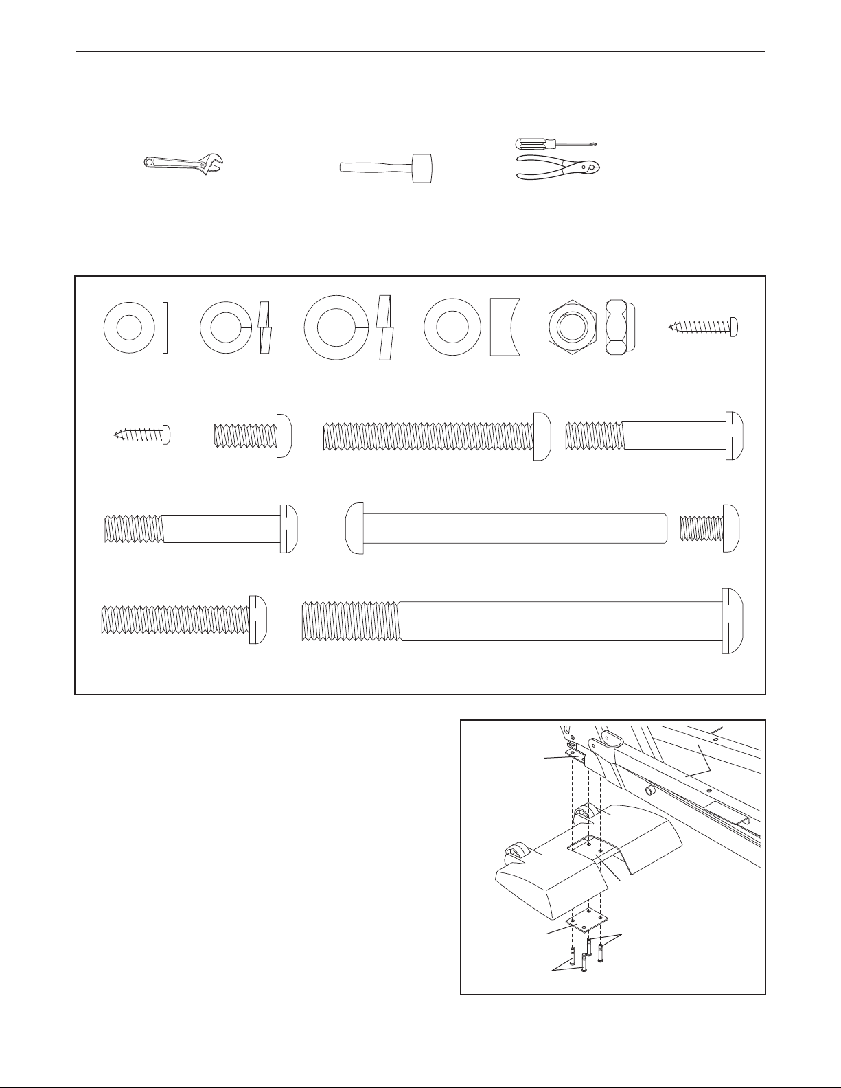
M8 x 54mm Button Screw (83)–4
M8 x 44mm Button Screw (84)–8
M6 x 16mm Patch
Screw (76)–4
M8 x 42mm Button
Bolt (85)–4
M10 Split
Washer (73)–2
M4 x 12mm
Round Head
Screw (96)–1
M6 Washer
(64)–2
7.6mm Spacer
(109)–2
M8 Jam Nut
(86)–6
M4 x 16mm
Screw (98)–4
M10 x 108mm Button Screw (70)–2
M8 x 38mm Button Bolt
(105)–2
M8 x 79mm Bolt Set (65)–2
M8 Split
Washer (130)–4
Assembly requires two people. Place all parts of the elliptical exerciser in a cleared area and remove the
packing materials. Do not dispose of the packing materials until assembly is completed. In addition to the four
included allen wrenches, assembly requires a phillips screwdriver , two adjustable
renches , a rubber mallet , and pliers .
w
Use the drawings below to identify the small parts required for assembly. The number in parenthesis below each
drawing is the key number of the part, from the PART LIST on pages 28 and 29. The number following the key
number is the quantity needed for assembly. Note: Some small parts may have been preassembled. If a part
is not in the parts bag, check to see if it has been preassembled.
1. Identify the Front Stabilizer (8). While another person
lifts the front of the Frame (1) and holds the Pedal
Legs (4, 5) in the position shown, attach the Front
Stabilizer to the Frame with four M8 x 44mm Button
Screws (84) and a Support Plate (104).
While another person lifts the rear of the Frame (1),
attach the Rear Stabilizer (not shown) to the Frame
in the same way.
1
1
104
84
8
84
4, 5
5
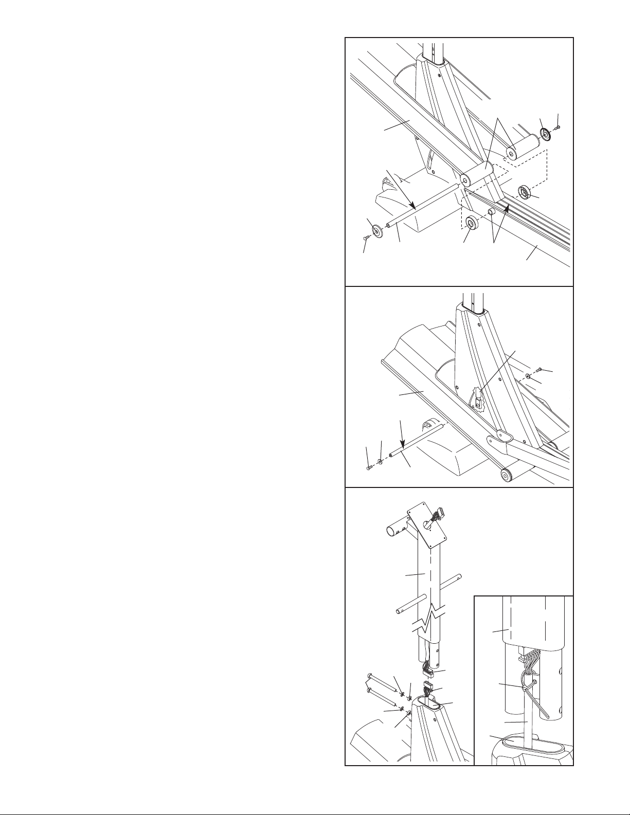
2. Identify the Pivot Axle (14), which is the longer of the
two axles. Slide a Ramp Cover (48) onto an M6 x
16mm Patch Screw (76) as shown. Tighten the Patch
crew into one end of the Pivot Axle. Apply a small
S
amount of the included grease to the Pivot Axle.
Have a second person hold the two Ramp Spacers
(99) against the sides of the Frame (1) so they cover
the indicated tubes on the Frame. Lift the Pedal Legs
(not shown) out of the way and align the round tubes
on the Ramp (3) with the Ramp Spacers. Make sure
that the Ramp is turned as shown in drawing 3
below. Insert the Pivot Axle (14) into the Ramp, the
Ramp Spacers, and the Frame. If necessary, tap the
Pivot Axle with a rubber mallet to insert it.
2
48
3
Grease
Tubes
48
76
99
Slide the other Ramp Cover (48) onto an M6 x 16mm
Patch Screw (76) as shown. Tighten the Patch Screw
into the other end of the Pivot Axle (14).
3. Slide an M6 Washer (64) onto an M6 x 16mm Patch
Screw (76). Tighten the Patch Screw into one end of
the Incline Axle (13). Apply a small amount of grease
to the Incline Axle.
Raise the Ramp (3). Insert the Incline Axle (13) into
the welded tube under one side of the Ramp, through
the motor screw, and then into the welded tube under
the other side of the Ramp. As you insert the Incline
Axle through the motor screw, make sure that the
motor screw does not turn.
Slide an M6 Washer (64) onto an M6 x 16mm Patch
Screw (76). Tighten the Patch Screw into the open
end of the Incline Axle (13).
4. Have another person hold the Upright (2) in the position shown.
Connect the Upper Wire Harness (115) to the Lower
Wire Harness (42). Insert the connectors on the Wire
Harnesses up into the Upright (2). Carefully pull the
upper end of the Upper Wire Harness to remove
the slack from the Wire Harnesses. See the inset
drawing. Attach the Lower Wire Harness to the Upright
with the Nylon Zip Tie (129). Pull the Nylon Zip Tie
tight and cut off the excess.
Insert the Upright (2) into the Frame (1). Be careful to
avoid pinching the Wire Harnesses (115, 42). Attach
the Upright with two M10 x 108mm Button Screws
(70), two M10 Split Washers (73), and two 7,6mm
Spacers (109); make sure that the curved sides of
the Spacers are facing the Upright. Be careful to
avoid damaging the Wire Harnesses with the
Button Screws.
3
4
70
76
76
Grease
64
73
73
109
3
14
2
13
109
115
42
Tubes
99
Do not pinch the
wire harnesses
during this step.
2
129
1
42
1
1
Motor
Screw
76
64
6
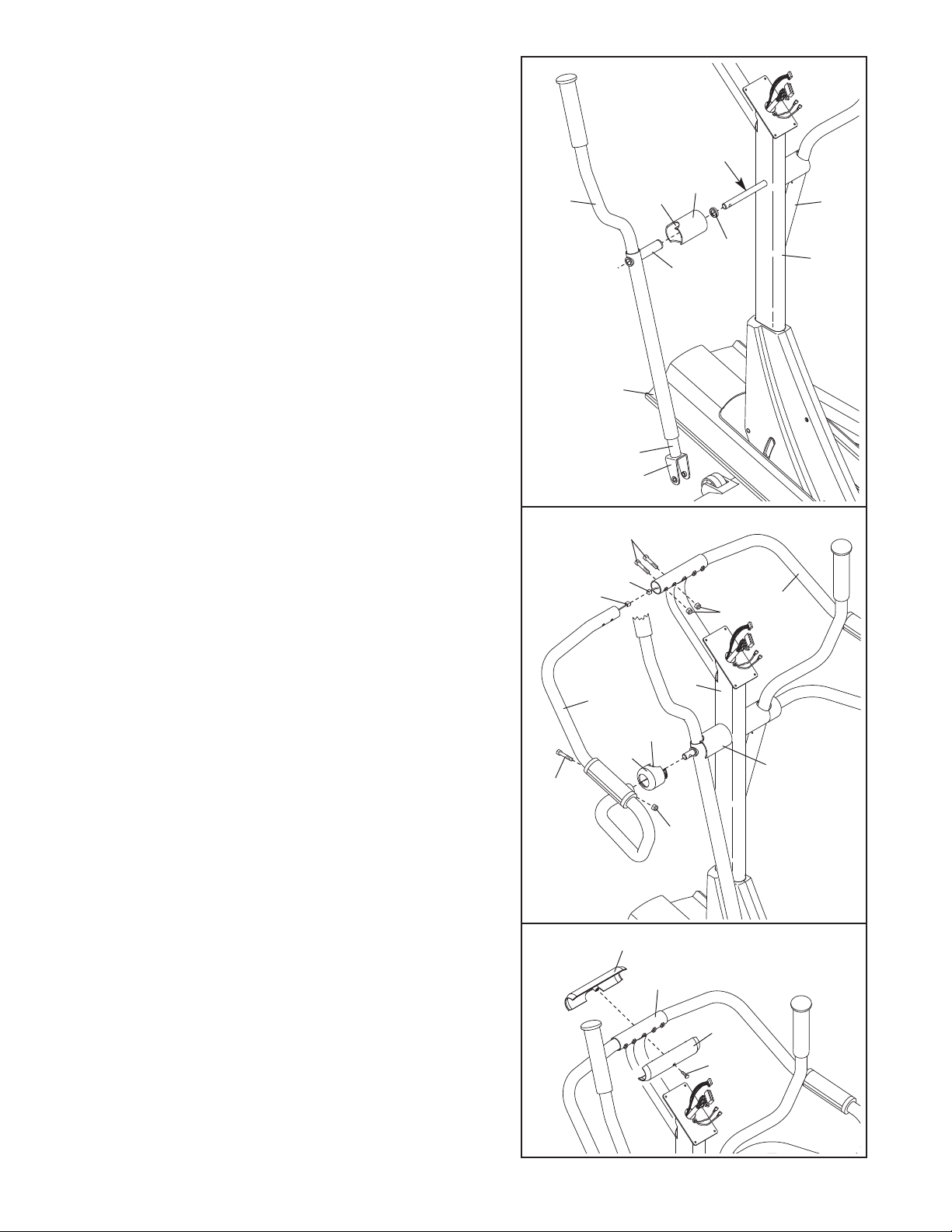
5. Slide a Weld Spacer (119) onto the axle on the left
side of the Upright (2); make sure that the open side
of the Weld Spacer is facing the Upright. Next, apply a
small amount of grease to the axle.
5
dentify the Left Upper Body Arm (118), which is
I
marked with a sticker. Remove the Upper Body Leg
(31) from the Left Upper Body Arm. Apply a small
amount of the included high-temperature lubricant to a
paper towel, and rub a thin film of the lubricant onto
the Upper Body Leg. Then, reinsert the Upper Body
Leg into the Left Upper Body Arm.
Slide a Handlebar Cover (26) onto the indicated tube
on the Left Upper Body Arm (118). Hold the Left Upper
Body Arm with one hand, hold the Upper Body Leg
(31) with your other hand, and slide the Left Upper
Body Arm onto the axle on the left side of the Upright
(2). Then, extend the Upper Body Leg until it rests on
the Ramp (3).
Repeat this step with the Right Upper Body Arm
(128).
6. Have another person hold the Left Handlebar (24)
near the Upright (2). Connect the left Pulse Sensor
Wire (20) to the Pulse Extension Wire (114). Next,
slide a Handlebar Cap (127) onto the lower end of the
Left Handlebar.
Slide the upper end of the Left Handlebar (24) into the
tube on the front of the Upright (2), while sliding the
lower end of the Left Handlebar onto the axle on the
left side of the Upright. Attach the upper end of the
Left Handlebar with two M8 x 42mm Button Bolts (85)
and two M8 Jam Nuts (86); be careful not to damage
the Wires (20, 114) as you insert the Button Bolts.
Make sure that the Jam Nuts are resting in the
hexagonal holes in the Left Handlebar. Attach the
lower end of the Left Handlebar with an M8 x 38mm
Button Bolt (105) and an M8 Jam Nut (86). Then,
press the tabs on the Handlebar Cap (127) into the left
Handlebar Cover (26).
6
18
1
105
3
Lubricate
85
114
20
24
127
utout
C
31
Cutout
26
Tube
2
86
Grease
119
86
23
26
28
1
2
Attach the Right Handlebar (23) in the same way.
7. Hold the halves of the Upper Handlebar Cover (25)
around the tube on the front of the Upright (2); be
careful not to damage the Wires (not shown).
Attach the Upper Handlebar Cover with an M4 x 12mm
Round Head Screw (96).
7
25
2
25
96
7
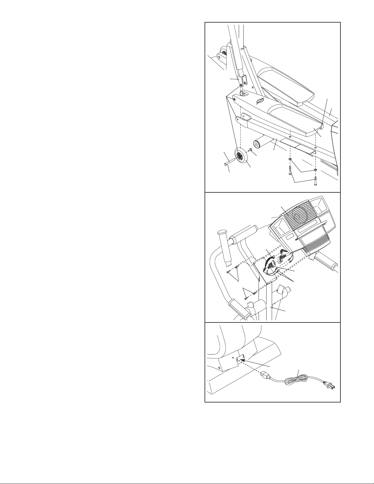
8. Apply a liberal amount of grease to the long side of
each M8 x 79mm Bolt Set (65).
Identify the Left Pedal (10), which has a notch near
the right side. Place the Left Pedal on the Left Pedal
Leg (4). Have a second person hold the bracket on the
left Upper Body Leg (31) inside of the bracket on the
Left Pedal Leg, and hold a Wheel (28) inside of the
bracket on the left Upper Body Leg.
8
31
Align the indicated holes, and attach the Left Pedal
(10), the left Upper Body Leg (31), and the Wheel (28)
to the Left Pedal Leg (4) with an M8 x 79mm Bolt Set
(65). Attach the rear of the Left Pedal to the Left Pedal
Leg with two M8 x 54mm Button Screws (83) and two
M8 Split Washers (130).
Repeat this step on the right side of the elliptical exerciser.
See step 4. Tighten the two M10 x 108mm Button
Screws (70).
9. Have another person hold the Console (17) near the
Upright (2).
Connect the Upper Wire Harness (115) to the wire harness on the Console (17). Connect the Pulse
Extension Wire (114) to the pulse wire on the Console.
Next, locate the two ground wires that are attached
with a screw to the Upright (2). Connect the ground
wires to the two smallest wires on the Console.
Carefully insert all excess wiring up into the Console
(17) and down into the Upright (2). Attach the Console
to the Upright with four M4 x 16mm Screws (98).
(Note: The Screws may be shipped in the console
box.) Be careful to avoid pinching the wires.
Holes
Grease
65
9
Do not pinch
the wires
during this step.
98
Notch
5
10
4
65
28
130
83
17
114
115
Ground
Wires
2
10.Plug the Power Cord (116) into the Power Socket
(117) at the rear of the elliptical exerciser.
11. Make sure that all parts of the elliptical exerciser are properly tightened. Cover the floor beneath the
elliptical exerciser to protect the floor from damage. Note: Some extra hardware may be left over.
10
117
116
8
HOW TO USE THE CHEST PULSE SENSOR
To get the best performance from the chest pulse sensor, please read the instructions below.
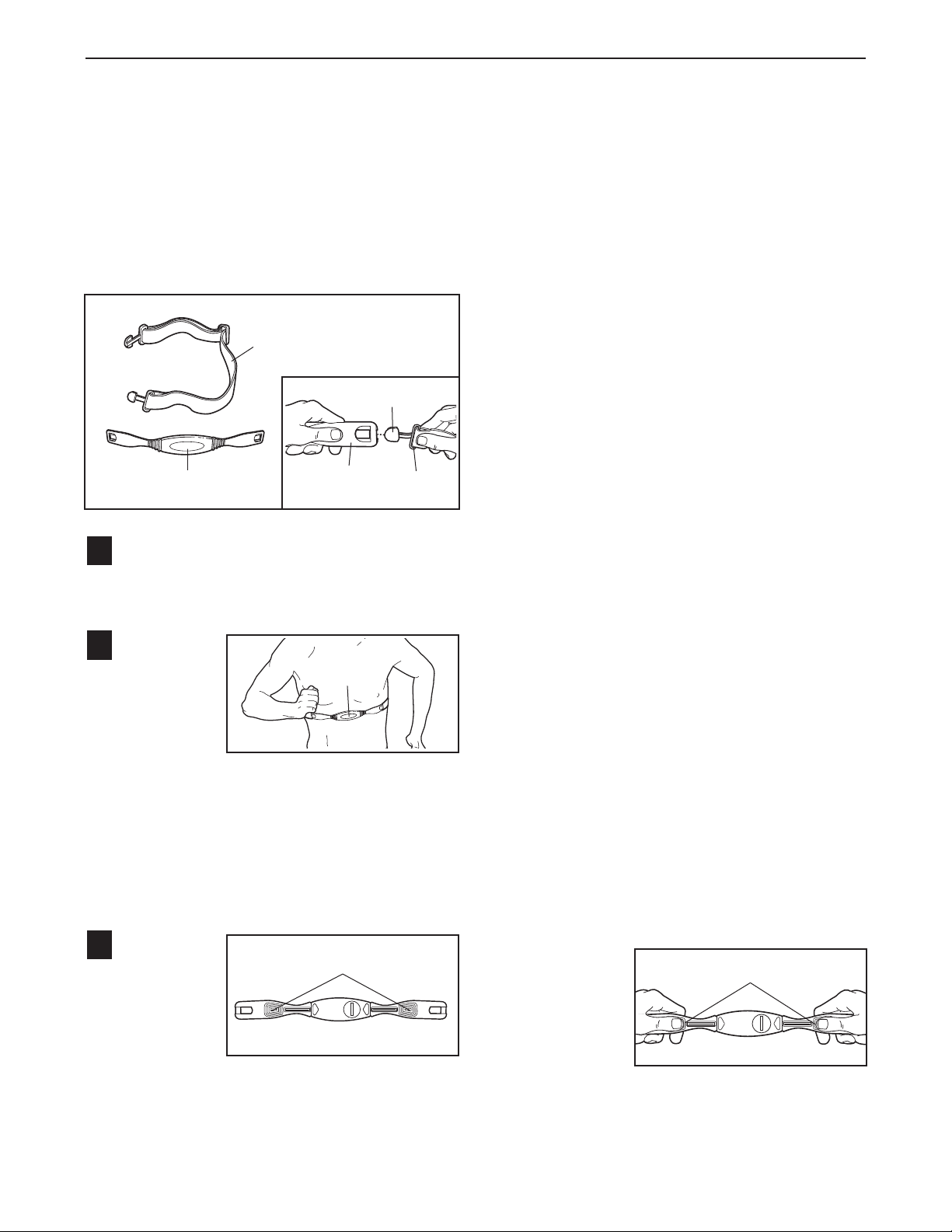
HOW TO PUT ON THE CHEST PULSE SENSOR
The chest pulse sensor consists of two components:
the chest strap and the sensor unit. Follow the steps
below to put on the chest pulse sensor.
Chest Strap
Tab
Sensor Unit
See the inset drawing above. Insert the tab on
1
one end of the chest strap through one end of the
sensor unit as shown. Then, press the end of the
sensor unit under the buckle on the chest strap.
Wrap the
2
chest pulse
sensor
around
your chest.
Attach the
free end of
the chest
strap to the sensor unit as described above.
Adjust the length of the chest strap, if necessary.
The chest pulse sensor should be under your
clothing, against your skin, and as high under the
pectoral muscles or breasts as is comfortable.
Make sure that the logo is facing forward and is
right-side-up.
Pull the
3
sensor unit
away from
your body
a few inches and
locate the
two elec-
Sensor
Unit
Logo
Electrode Areas
Buckle
trode areas on the inner side. Using a saline
solution such as saliva or contact lens solution,
et both electrode areas. Return the sensor unit
w
to a position against your chest.
CHEST PULSE SENSOR TROUBLESHOOTING
If the chest pulse sensor does not function properly, or if the displayed heart rate is excessively high
or low, try the steps below.
• Make sure that the chest pulse sensor is worn
exactly as described in step 2 at the left. If the chest
pulse sensor does not function when positioned as
described, move it slightly lower or higher on your
chest.
• Each time you use the chest pulse sensor, use
saline solution such as saliva or contact lens solution to wet the two electrode areas on the sensor
unit (see the drawing in step 3 at the left). If heart
rate readings do not appear until you begin perspiring, re-wet the electrode areas.
• Make sure that you are within armʼs length of the
console. For the console to display heart rate
readings, the user must be within armʼs length of
the console.
• The chest pulse sensor is designed to work with
people who have normal heart rhythms. Heart rate
reading problems may be caused by medical conditions such as premature ventricular contractions
(pvcs), tachycardia bursts, and arrhythmia.
• The operation of the chest pulse sensor can be
affected by magnetic interference caused by high
power lines or other sources. If it is suspected that
magnetic interference may be causing a problem,
try relocating your exercise equipment.
• If the chest pulse sensor still does not function properly, test the chest pulse sensor in the following way:
Hold the chest
pulse sensor
and place your
thumbs over
the electrode
areas as
shown.
Electrode Areas
9
Next, hold the chest pulse sensor near the console.
While holding one thumb stationary, begin tapping
the other thumb against the electrode area at a rate
f about one tap per second. Check the heart rate
o
reading on the console.
• If the chest pulse sensor does not function properly
after you have followed all of the above instructions,
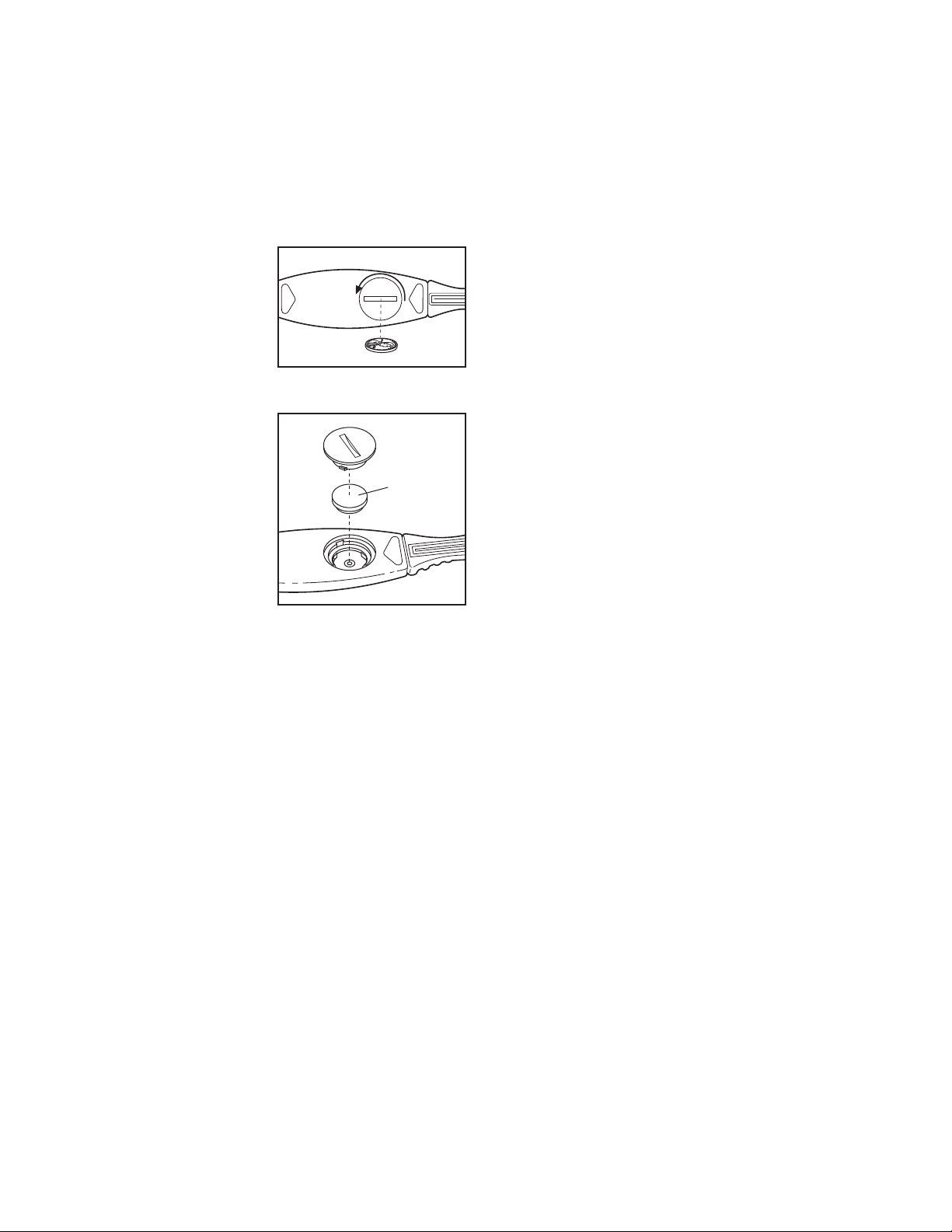
the battery should be replaced in the following way:
Locate the battery
cover on the back of
the sensor unit. Insert
a coin into the slot in
the cover, turn the
cover counterclockwise, and remove the
cover.
Remove the old battery and insert a
new CR 2032 battery. Make sure that
the battery is
turned so the writing is on top.
Replace the battery
cover and turn it
clockwise to close it.
CR 2032
Battery
CHEST PULSE SENSOR CARE
• Thoroughly dry the chest pulse sensor after each
se. The chest pulse sensor is activated when the
u
electrode areas are wetted and the chest pulse sen-
or is put on; the chest pulse sensor shuts off when
s
it is removed and the electrode areas are dried. If
the chest pulse sensor is not dried after each use, it
may remain activated longer than necessary, draining the battery prematurely.
• Store the chest pulse sensor in a warm, dry place.
Do not store the chest pulse sensor in a plastic bag
or other container that may trap moisture.
• Do not expose the chest pulse sensor to direct
sunlight for extended periods of time. Do not expose
the chest pulse sensor to temperatures above 122°
Fahrenheit (50° Celsius) or below 14° Fahrenheit
(-10° Celsius).
• Do not excessively bend or stretch the sensor unit
when using or storing the chest pulse sensor.
• Clean the sensor unit using a damp cloth—never
use alcohol, abrasives, or chemicals. The chest
strap may be hand washed and air dried.
10
 Loading...