


NordicTrack 9800 User Manual

Model No.
Serial No.
The model number and serial number are found in the location shown
below. Write the model number and
serial number in the space above.
Serial Number Decal
QUESTIONS?
At FreeMotion Fitness, Inc., we’re
committed to providing complete
customer satisfaction. For assistance, please contact your distributor.
CAUTION
Read all precautions and instructions in this manual before using
this equipment. Keep this manual
for future reference.
SER'S
U
ANUAL
M

TABLE OF CONTENTS
SECTION 1
Important Precautions . . . . . . . . . . . . . . . . . . . . . . . . . . . . . . . . . . . . . . . . . . . . . . . . . . . . . . . . . . . . .3
Warning Decal Placement . . . . . . . . . . . . . . . . . . . . . . . . . . . . . . . . . . . . . . . . . . . . . . . . . . . . . . . . . .5
Before You Begin . . . . . . . . . . . . . . . . . . . . . . . . . . . . . . . . . . . . . . . . . . . . . . . . . . . . . . . . . . . . . . . .6
How to Set Up the INCLINE TRAINER . . . . . . . . . . . . . . . . . . . . . . . . . . . . . . . . . . . . . . . . . . . . . . . .7
How to Move the INCLINE TRAINER . . . . . . . . . . . . . . . . . . . . . . . . . . . . . . . . . . . . . . . . . . . . . . . . .9
How to Connect the INCLINE TRAINER . . . . . . . . . . . . . . . . . . . . . . . . . . . . . . . . . . . . . . . . . . . . . .10
How to Upgrade your Console . . . . . . . . . . . . . . . . . . . . . . . . . . . . . . . . . . . . . . . . . . . . . . . . . . . . .11
SECTION 2
How to Use the Basic Console . . . . . . . . . . . . . . . . . . . . . . . . . . . . . . . . . . . . . . . . . . . . . . . . . . . . .13
How to Use the Workout TV Console . . . . . . . . . . . . . . . . . . . . . . . . . . . . . . . . . . . . . . . . . . . . . . . .25
SECTION 3
Preventive Maintenance . . . . . . . . . . . . . . . . . . . . . . . . . . . . . . . . . . . . . . . . . . . . . . . . . . . . . . . . . .27
Six-month Preventive Maintenance Record . . . . . . . . . . . . . . . . . . . . . . . . . . . . . . . . . . . . . . . . . . .29
Troubleshooting . . . . . . . . . . . . . . . . . . . . . . . . . . . . . . . . . . . . . . . . . . . . . . . . . . . . . . . . . . . . . . . .31
SECTION 4
Exercise Guidelines . . . . . . . . . . . . . . . . . . . . . . . . . . . . . . . . . . . . . . . . . . . . . . . . . . . . . . . . . . . . .33
SECTION 5
Part List . . . . . . . . . . . . . . . . . . . . . . . . . . . . . . . . . . . . . . . . . . . . . . . . . . . . . . . . . . . . . . . . . . . . . . .37
Exploded Drawing . . . . . . . . . . . . . . . . . . . . . . . . . . . . . . . . . . . . . . . . . . . . . . . . . . . . . . . . . . . . . . .39
How to Order Replacement Parts . . . . . . . . . . . . . . . . . . . . . . . . . . . . . . . . . . . . . . . . . . . . . . . . . . .42
NordicTrack is a registered trademark of ICON Health & Fitness, Inc.
1

2

IMPORTANT PRECAUTIONS
WARNING:To reduce the risk of burns, fire, electric shock, or injury to persons, read the
ollowing important precautions and information before operating the INCLINE TRAINER.
f
. It is the responsibility of the owner to ensure
1
hat all users of the INCLINE TRAINER are ad-
t
equately informed of all warnings and precautions.
2. Use the INCLINE TRAINER only as described
in this manual.
3. Place the INCLINE TRAINER on a level surface, with at least eight feet of clearance behind it. Do not place the INCLINE TRAINER on
any surface that blocks air openings. To protect the floor or carpet from damage, place a
mat under the INCLINE TRAINER.
4. Keep the INCLINE TRAINER indoors, away
from moisture and dust. Do not place the INCLINE TRAINER in a garage or covered patio,
or near water.
5. Do not operate the INCLINE TRAINER where
aerosol products are used or where oxygen is
being administered.
6. Do not operate the INCLINE TRAINER until it
is properly assembled (see HOW TO SET UP
THE INCLINE TRAINER on page 7).
7. Regularly inspect and tighten all parts of the
INCLINE TRAINER.
8. Keep children under the age of 12 and pets
away from the INCLINE TRAINER at all times.
9. The INCLINE TRAINER should not be used by
persons weighing more than 160 kg (350 lbs.).
10. Never allow more than one person on the
INCLINE TRAINER at a time.
11. Wear appropriate exercise clothes when
using the INCLINE TRAINER. Do not wear
loose clothes that could become caught in
the INCLINE TRAINER. Athletic support
clothes are recommended for both men and
women.
Always wear athletic shoes. Never
use the INCLINE TRAINER with bare feet,
wearing only stockings, or in sandals.
2. When connecting the power cord (see page 10),
1
lug the power cord into a grounded circuit
p
capable of carrying 10 or more amps. No other
appliance should be on the same circuit. Do not
use an extension cord.
13. Keep the power cord away from heated surfaces.
14. Never move the walking belt while the power
is turned off. Do not operate the INCLINE
TRAINER if the power cord or plug is damaged or if the INCLINE TRAINER is not working properly. (See BEFORE YOU BEGIN on
page 6 if the INCLINE TRAINER is not working
properly.)
15. Never start the INCLINE TRAINER while you
are standing on the walking belt. Always hold
the handrails while using the INCLINE
TRAINER.
16. The INCLINE TRAINER is capable of high
speeds. Adjust the speed in small increments
to avoid sudden jumps in speed.
17. The pulse sensor is not a medical device.
Various factors, including the user's movement, may affect the accuracy of heart rate
readings. The pulse sensor is intended only
as an exercise aid in determining heart rate
trends in general.
Never leave the INCLINE TRAINER unat-
18.
tended while it is running. Always remove the
key, unplug the power cord, and switch the
on/off circuit breaker to the off position when
the INCLINE TRAINER is not in use.
19. Do not change the incline of the INCLINE
TRAINER by placing objects under it.
20. Never insert or drop any object into any
opening.
Make sure to perform all maintenance proce
21.
dures outlined in this manual. Failure to do so
will void the warranty and may result in dam
age to the INCLINE TRAINER.
-
-
3

escribed in this manual. Servicing other than
2.
2
DANGER:A
cord immediately after use, before cleaning
the INCLINE TRAINER, and before performing
the maintenance and adjustment procedures
lways unplug the power
d
the procedures in this manual should be performed by an authorized service representative only.
WARNING:Before beginning this or any exercise program, consult your physician. This
is especially important for persons over the age of 35 or persons with pre-existing health problems.
Read all instructions before using. ICON assumes no responsibility for personal injury or property
damage sustained by or through the use of this product.
SAVE THESE INSTRUCTIONS
4
HAZARDOUS
VOLTAGE
Disconnect power
before servicing.
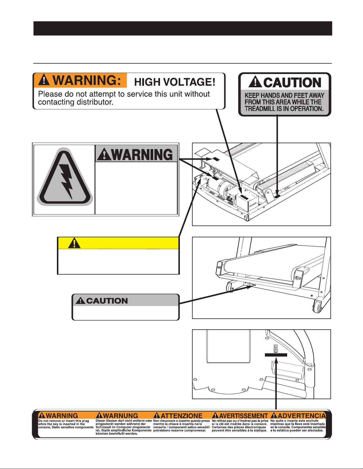
WARNING DECAL PLACEMENT
CAUTION
Overtightening of J-bolt may result
in severe motor damage. Refer to the
service manual for proper tensioning
procedure, or contact Customer Care.
:
HIGH VOLTAGE
Disconnect line cord from
outlet before servicing.
The decals shown below are found on the INCLINE TRAINER. If any decal is missing or illegible, please
contact your distributor to order a free replacement decal. Apply the decal in the location shown.
Note: This decal is shown at 75% of actual size.
Note: This decal
is shown at 80%.
Note: This decal is shown at 85%.
Note: There
is one decal
on each side.
5

BEFORE YOU BEGIN
Congratulations for selecting the revolutionary NordicTrack®9800 INCLINE TRAINER. The NordicTrack
9800 INCLINE TRAINER offers an impressive array of
eatures to make your workouts more effective and
f
enjoyable.
Polar®Chest Pulse Sensor Receiver
Console
Accessory Tray
Handrail
Key/Clip
For your benefit, read this manual carefully before
using the 9800 INCLINE TRAINER. If you have
questions after reading the manual, please contact
our distributor.
y
efore reading further, please familiarize yourself with
B
the parts that are labeled in the drawing below.
Handgrip Pulse Sensor
Water Bottle Holder
Cushioned Walking Platform
Walking Belt
Foot Rail
Roller Adjustment Bolt
On/off Circuit Breaker
Power Cord
6

HOW TO SET UP THE INCLINE TRAINER
Assembly requires two persons. Set the INCLINE TRAINER in a cleared area and remove all packing materials.
Do not dispose of the packing materials until assembly is completed. Assembly can be completed using the
included allen wrenches.
Note: The underside of the INCLINE TRAINER walking belt is coated with high-performance lubricant. During
hipping, a small amount of lubricant may be transferred to the top of the walking belt or the shipping carton. This
s
is a normal condition and does not affect INCLINE TRAINER performance. If there is lubricant on top of the walking belt, simply wipe off the lubricant with a soft cloth and a mild, non-abrasive cleaner.
1. Slide the Right and Left Uprights (96, 107) onto the
brackets near the front of the Base Frame (52).
sure that the Uprights are on the correct sides; the
indicated holes must be facing the INCLINE
TRAINER.
Raise the Left Upright (107) until the lower hole in the
front of the Left Upright is aligned with the upper hole in
the bracket as shown. Thread an Upright Bolt (106) into
the Left Upright and the bracket.
the Upright Bolt yet.
Repeat this step with the Right Upright (96).
2. While a second person holds the Handrail (94) near the
Uprights (96, 107), feed the wires in both sides of the
Handrail down into the Uprights. Pull the ends of the
wires out of the lower ends of the Uprights and remove
the wire ties from the ends of the wires.
Finger tighten four Handrail Bolts (93) into the Handrail
(94) and the Uprights (96, 107) as shown. Be careful to
avoid pinching the wires in the Handrail.
Do not fully tighten
Make
1
106
2
93
52
142
94
96
Holes
89
106
107
52
10
93
Note: The Accessory Holder (142) and the Cup Holder
(10) are replaceable. If these parts become dislodged
from the Console (89), press them back into place.
3. Connect the Right Upright Wire Harness (105), the TV
Cable (33), and the Left Upright Wire Harness (131) in
the indicated locations. Push all of the excess wire up
into the Uprights (96, 107). Make sure that all wires are
fully connected. Note: Regardless of which console
your INCLINE TRAINER has, connect all wires so that
the console can later be upgraded if desired.
Refer to step 1. While a second person holds the
Uprights (96, 107), remove the Upright Bolts (106). Slide
the Uprights fully onto the Base Frame (52). Be careful
to avoid pinching your hands or the wires.
96
3
105
96
Wires
107
107
33
131
7

4. Thread two Upright Bolts (106) into each Upright (96,
107) in the indicated locations. Do not tighten the
pright Bolts yet.
U
4
106
96
107
106
5. Next it will be necessary to adjust the incline of the
INCLINE TRAINER. First, plug in the power cord (refer
to page 10). Next, make sure that the on/off circuit
breaker is in the on position (refer to step 2 on page 14).
Place the Key (90) in the Console (89). Press the
QUICK INCLINE button labeled “21” to adjust the incline to 21%. Then, remove the Key.
Move the on/off circuit breaker to the off position
and unplug the power cord.
6. Thread two additional Upright Bolts (106) into each
Upright (96, 107) in the indicated locations. Tighten all
eight Upright Bolts in the Uprights.
5
89
6
106
QUICK INCLINE
buttons
96
106
90
107
106
7. Refer to step 2 on page 7 and tighten the four Handrail
Bolts (93).
Place the Upright Caps (92) over the Handrail (94) and
the upper ends of the Uprights (96, 107). Press the
Handrail Caps against the hook-and-loop fastener strips
on the Uprights. Attach each Handrail Cap with four
Upright Cap Screws (91).
Upright Cap Screws.
Do not overtighten the
7
91
94
92
91
96
91
107
92
91
8
8. After the INCLINE TRAINER is placed in the location
where it will be used (refer to HOW TO MOVE THE
NCLINE TRAINER below), make sure that both Rear
I
Feet (66) and both front Wheels (not shown) rest firmly
n the floor. If the INCLINE TRAINER rocks even
o
slightly, turn the right Rear Foot clockwise or counterclockwise until the rocking motion is eliminated.
9. Make sure that all parts are properly tightened before you use the INCLINE TRAINER. Keep the included
allen wrenches for adjustment purposes. To protect the floor or carpet from damage, place a mat under the
INCLINE TRAINER.
8
66
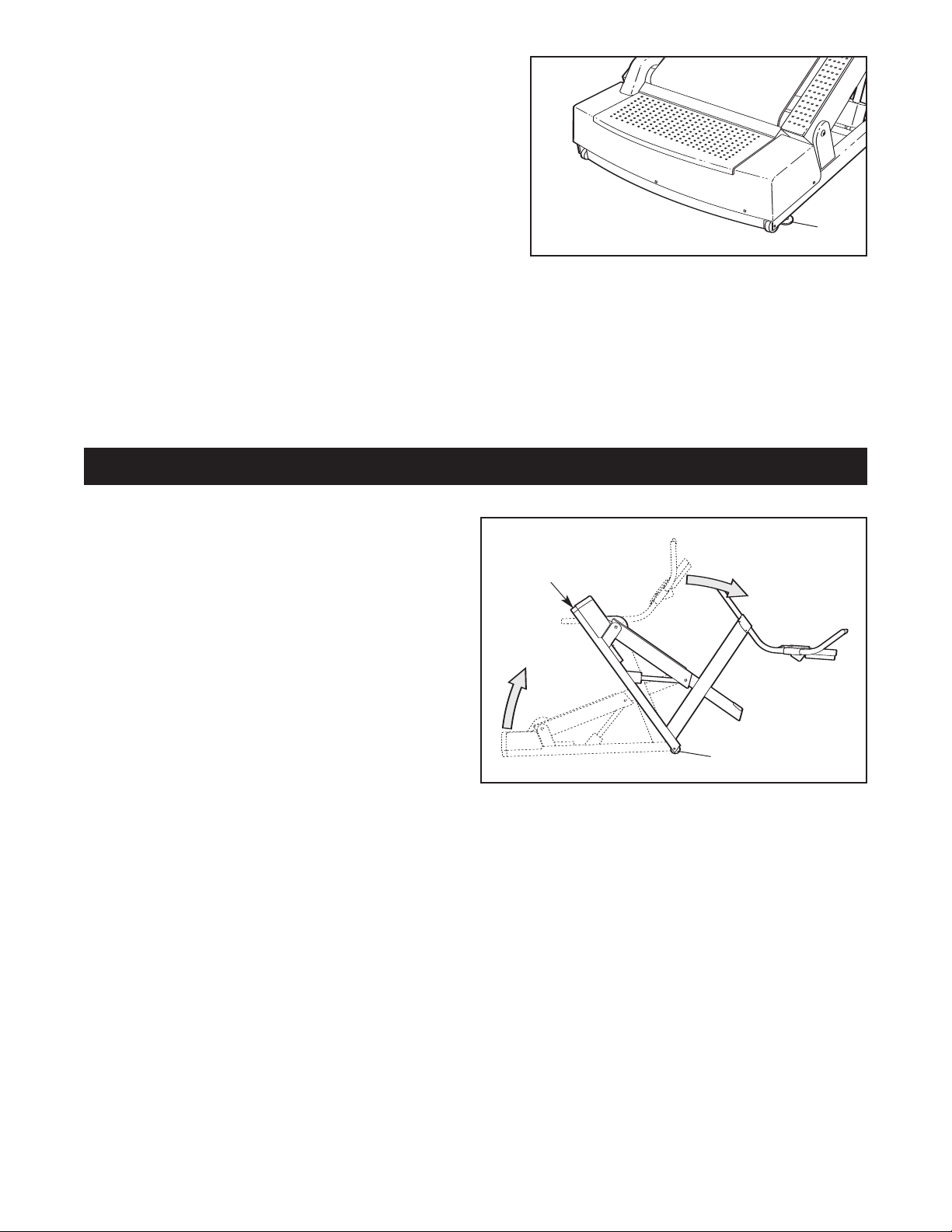
HOW TO MOVE THE INCLINE TRAINER
Before moving the INCLINE TRAINER, adjust the
incline to 30% and then unplug the power cord.
Note: It may be necessary to disconnect the CATV
cable and the network wire from the INCLINE
TRAINER, depending on how far the INCLINE
TRAINER will be moved.
Due to the size and weight of the INCLINE
TRAINER, moving it requires two persons. While
one person lifts the indicated end of the INCLINE
TRAINER, firmly hold the handrails and tip the INCLINE TRAINER forward until it rolls on the front
wheels. Carefully move the INCLINE TRAINER to
the desired location and then lower it back to the
level position. Note: Another way to move the INCLINE TRAINER is to have one person stand on
each side of it, lift the frame, and move it on the rear wheels.
CAUTION:
attempt to move the INCLINE TRAINER over uneven surfaces.
To reduce the risk of injury, use extreme caution while moving the INCLINE TRAINER. Do not
Rear
Wheels
Lift
Here
Tip
Handrails
Front Wheels
9

HOW TO CONNECT THE INCLINE TRAINER
FR/SP
GR
UK
IT
OW TO CONNECT THE POWER CORD
H
This product must be grounded.
function or break down, grounding provides a path of
east resistance for electric current to reduce the risk
l
f electric shock.
o
how the power cord should be connected in the
UK, Germany, Italy, Spain, or France. To connect
the power cord in other countries, refer to the
instruction sheet accompanying this manual.
ote: These instructions describe
N
If it should mal-
2
Germany
rance
F
Spain
DANGER:Improper connection
of the equipment-grounding conductor can
result in an increased risk of electric shock.
Check with a qualified electrician or service
man if you are in doubt as to whether the
product is properly grounded. Do not modify
the plug provided with the product—if it will
not fit the outlet, have a proper outlet
installed by a qualified electrician. Do not use
an adapter to connect the plug to an improper
receptacle.
This product is
for use on a dedicated circuit. In
the UK,
Germany, Italy,
Spain, or
France, use a
dedicated 10amp, 240-volt
circuit. No other
appliance should
be on the same
circuit. The product is equipped with a cord having an
equipment-grounding conductor and a grounding plug.
Plug one end of the cord into the INCLINE TRAINER
as shown in drawing 1. Attach the cord bracket over
the cord with the included allen wrench and the two
bracket screws.
Next, plug the grounding plug into a receptacle as
shown in drawing 2 at the right. Do not modify the plug
or the receptacle. Do not use an adapter, a surge pro
tector, or an extension cord.
1
Bracket
Screws
Bracket
-
Cord
Cord
UK
HOW TO CONNECT A CATV CABLE
If your INCLINE TRAINER has the Workout TV console, a CATV cable must be connected to the IN-
CLINE TRAINER for cable TV stations to be viewed.
Locate the cable
jack on the front of
the INCLINE
TRAINER.
Connect the CATV
cable to the cable
jack using the PAL
adapter. Route the
cable so that it will
not be pinched or
crushed by the wheels when the incline is changed.
A satellite receiver, VCR, or DVD player can also be
connected to the INCLINE TRAINER. Connect a CATV
cable from the coaxial output on your equipment (usu
ally labeled TV OUT or RF OUT) to the cable jack on
the front of the INCLINE TRAINER.
Note: Audio/video equipment without coaxial outputs
-
(some satellite receivers and DVD players) requires a RF
modulator to work correctly with the INCLINE TRAINER.
RF modulators are not available from FreeMotion
Fitness, but are available at electronics stores. See the
owner's manual for the equipment you wish to connect to
determine if an RF modulator is needed.
Cable Jack
10
Italy
-

HOW TO UPGRADE YOUR CONSOLE
Your INCLINE TRAINER has been pre-configured to operate with the Basic console and the Workout TV console
(see the drawings below).
For information about the features of the Basic console, refer to page 13. To learn about the state-of-the-art
Workout TV console, refer to page 25.
To upgrade your console whenever you choose, simply contact your local FreeMotion Fitness Sales
Representative.
Basic Console
Workout
TV Console
11

NOTES
12
 Loading...