


NordicTrack NEL07940 User Manual

CAUTION
Read all precautions and instructions in this manual before using
this equipment. Keep this manual
for future reference.
Model No. NEL07940
Serial No. _
Serial Number
Decal
QUESTIONS?
If you have questions, or if there
are missing parts, we will guarantee complete satisfaction
through direct assistance from
our factory.
TO AVOID DELAYS, PLEASE
CALL DIRECT TO OUR TOLLFREE CUSTOMER HOT LINE.
The trained technicians on our
customer hot line will provide
immediate assistance, free of
charge to you.
CUSTOMER HOT LINE:
1-888-825-2588
Mon.–Fri., 6 a.m.–6 p.m. MST
USER’S MANUAL
Patent Pending
Visit our website at
www.nordictrack.com
new products, prizes,
fitness tips, and much more!

TABLE OF CONTENTS
IMPORTANT PRECAUTIONS . . . . . . . . . . . . . . . . . . . . . . . . . . . . . . . . . . . . . . . . . . . . . . . . . . . . . . . . . . . . .2
BEFORE YOU BEGIN . . . . . . . . . . . . . . . . . . . . . . . . . . . . . . . . . . . . . . . . . . . . . . . . . . . . . . . . . . . . . . . . . . .3
ASSEMBLY . . . . . . . . . . . . . . . . . . . . . . . . . . . . . . . . . . . . . . . . . . . . . . . . . . . . . . . . . . . . . . . . . . . . . . . . . . .4
HOW TO USE THE ELLIPTICAL EXERCISER . . . . . . . . . . . . . . . . . . . . . . . . . . . . . . . . . . . . . . . . . . . . . . . . .7
MAINTENANCE AND TROUBLESHOOTING . . . . . . . . . . . . . . . . . . . . . . . . . . . . . . . . . . . . . . . . . . . . . . . . .19
CONDITIONING GUIDELINES . . . . . . . . . . . . . . . . . . . . . . . . . . . . . . . . . . . . . . . . . . . . . . . . . . . . . . . . . . . .20
PART LIST . . . . . . . . . . . . . . . . . . . . . . . . . . . . . . . . . . . . . . . . . . . . . . . . . . . . . . . . . . . . . . . . . . . . . . . . . . .21
EXPLODED DRAWING . . . . . . . . . . . . . . . . . . . . . . . . . . . . . . . . . . . . . . . . . . . . . . . . . . . . . . . . . . . . . . . . .22
HOW TO ORDER REPLACEMENT PARTS . . . . . . . . . . . . . . . . . . . . . . . . . . . . . . . . . . . . . . . . . . .Back Cover
LIMITED WARRANTY . . . . . . . . . . . . . . . . . . . . . . . . . . . . . . . . . . . . . . . . . . . . . . . . . . . . . . . . . . .Back Cover
2
IMPORTANT PRECAUTIONS
WARNING:
To reduce the risk of serious injury, read the following important precau-
tions before using the elliptical exerciser.
1. Read all instructions in this manual before
using the elliptical exerciser.
2. It is the responsibility of the owner to ensure
that all users of the elliptical exerciser are
adequately informed of all precautions.
3. The elliptical exerciser is intended for
in-home use only. Do not use the elliptical
exerciser in a commercial, rental, or institutional setting.
4. Place the elliptical exerciser on a level surface, with a mat beneath it to protect the
floor or carpet. Keep the elliptical exerciser
indoors, away from moisture and dust.
5. Inspect and properly tighten all parts regularly. Replace any worn parts immediately.
6. Keep children under age 12 and pets away
from the elliptical exerciser at all times.
7. The elliptical exerciser should not be used
by persons weighing more than 250 pounds.
8. Wear appropriate exercise clothing when
using the elliptical exerciser. Always wear
athletic shoes for foot protection.
9. Always hold the handgrip pulse sensor or
the handlebars when mounting, dismounting, or using the elliptical exerciser.
10. Keep your back straight when using the elliptical exerciser; do not arch your back.
11. If you feel pain or dizziness while exercising, stop immediately and cool down.
12. The pulse sensor is not a medical device.
Various factors may affect the accuracy of
heart rate readings. The pulse sensor is
intended only as an exercise aid in determining heart rate trends in general.
13. When you stop exercising, allow the pedals
to slowly come to a complete stop. The elliptical exerciser does not have a free wheel;
the pedals will continue to move until the
flywheel stops.
WARNING:Before beginning this or any exercise program, consult your physician.
This is especially important for persons over the age of 35 or persons with pre-existing health problems. Read all instructions before using. ICON assumes no responsibility for personal injury or
property damage sustained by or through the use of this product.
NordicTrack is a registered trademark of ICON Health & Fitness, Inc.
3
BEFORE YOU BEGIN
Congratulations for selecting the new NordicTrack
®
CX 925 elliptical exerciser. The CX 925 is an incredibly smooth exerciser that moves your feet in a natural
elliptical path, minimizing the impact on your knees
and ankles. And the unique CX 925 offers an impressive array of features to help you achieve your fitness
goals in the convenience of your home. Welcome to a
whole new world of natural, elliptical-motion exercise
from NordicTrack.
For your benefit, read this manual carefully before
you use the elliptical exerciser. If you have ques-
tions after reading this manual, please call our
Customer Service Department toll-free at 1-888-8252588, Monday through Friday, 6 a.m. until 6 p.m.
Mountain Time (excluding holidays). To help us assist
you, please note the product model number and serial
number before calling. The model number is
NEL07940. The serial number can be found on a
decal attached to the elliptical exerciser (see the front
cover of this manual for the location of the decal).
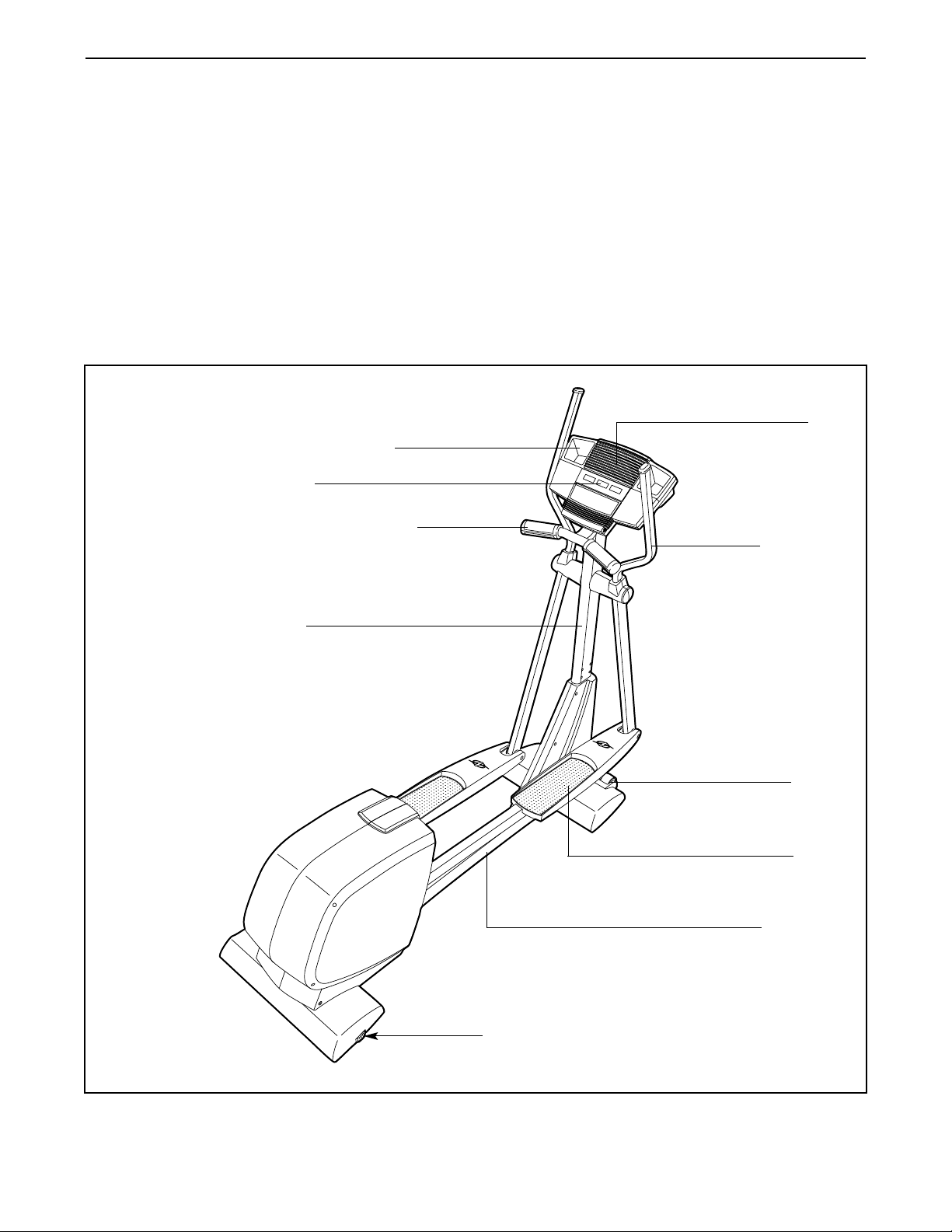
Before reading further, please familiarize yourself with
the parts that are labeled in the drawing below.
Water Bottle Holder*
*No water bottle is included
Handlebar
Handgrip Pulse Sensor
FRONT
BACK
RIGHT SIDE
Wheel
Pedal
Fan
Console
Upright
Leveling Foot
Pedal Leg
4
ASSEMBLY
Assembly requires two persons. Place all parts of the elliptical exerciser in a cleared area and remove the
packing materials. Do not dispose of the packing materials until assembly is completed.
Assembly requires the included allen wrenches and your own phillips screwdriver and
rubber mallet .
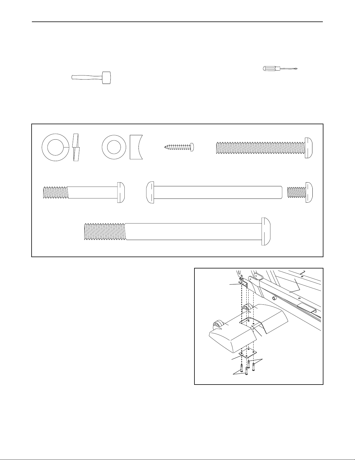
As you assemble the elliptical exerciser, use the drawings below to identify the small parts used in assembly.
The number in parentheses below each drawing refers to the key number of the part, from the PART LIST on
page 21. The second number refers to the quantity used in assembly. Note: Some small parts may have been
pre-assembled. If a part is not in the parts bag, check to see if it is pre-assembled.
1. Identify the Front Stabilizer (8). While another person
lifts the front of the Frame (1) and holds the Pedal
Legs (4, 5) in the position shown, attach the Front
Stabilizer to the Frame with four M8 x 44mm Button
Screws (84) and a Support Plate (64).
While another person lifts the rear of the Frame (1),
attach the Rear Stabilizer (not shown) to the Frame
in the same way.
1
8
4, 5
1
64
84
84
M10 Split
Washer (73)–2
M8 x 44mm Button Screw (84)–8
7.6mm Spacer
(47)–2
M10 x 108mm Button Screw (70)–2
M4 x 16mm
Screw (94)–4
M8 x 54mm Button Screw (83)–4
M8 x 79mm Bolt Set (65)–2
5
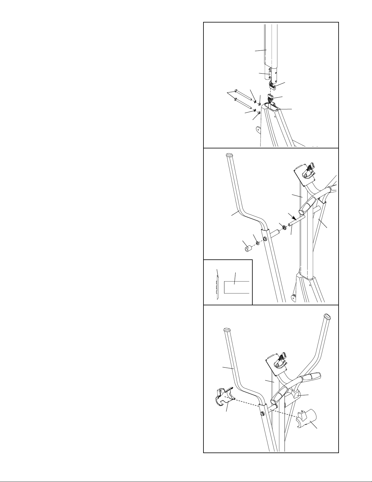
2. Have another person hold the Upright (2) in the position shown. Make sure that the Upright is turned as
shown in drawing 3 below, and that the Upper Wire
Harness (30) is on the right side of the indicated
metal plate.
Connect the Upper Wire Harness (30) to the Lower
Wire Harness (42). Carefully pull the upper end of
the Upper Wire Harness to remove the slack from
the Wire Harnesses. Insert the Upright (2) into the
Frame (1). Be careful to avoid disconnecting or
pinching the Wire Harnesses. Attach the Upright with
two M10 x 108mm Button Screws (70), two M10 Split
Washers (73), and two 7.6mm Spacers (47). Make
sure that the curved sides of the Spacers are facing the Upright. Be careful to avoid damaging the
Wire Harnesses with the Button Screws. Do not
tighten the Button Screws yet.
2
30
Plate
70
42
1
73
73
47
2
47
3
31
29
28
Grease
2
96
29
3. Slide a Weld Spacer (28) onto the axle on the left side
of the Upright (2), with the open side of the Weld
Spacer facing the Upright. Apply a small amount of
grease to the axle.
Slide an Upper Body Arm (29) onto the axle on the left
side of the Upright (2). Using the included Push Nut
Tool (96), tap a Push Nut (31) onto the axle; make
sure that the Push Nut is turned as shown in the
inset drawing.
Attach the other Upper Body Arm (29) to the right
side of the Upright (2) in the same way.
26
29
2
26
26
4. Look inside one of the Handlebar Covers (26) and
locate the square tabs connecting the two halves.
Gently lift the tabs and disconnect the halves.
Hold the two halves of the Handlebar Cover (26)
around the tube on the left side of the Upright (2). Align
the halves and press them together until they lock.
Attach the other Handlebar Cover (26) to the right side
of the Upright (2) in the same way.
4
Axle
Axle
31
6
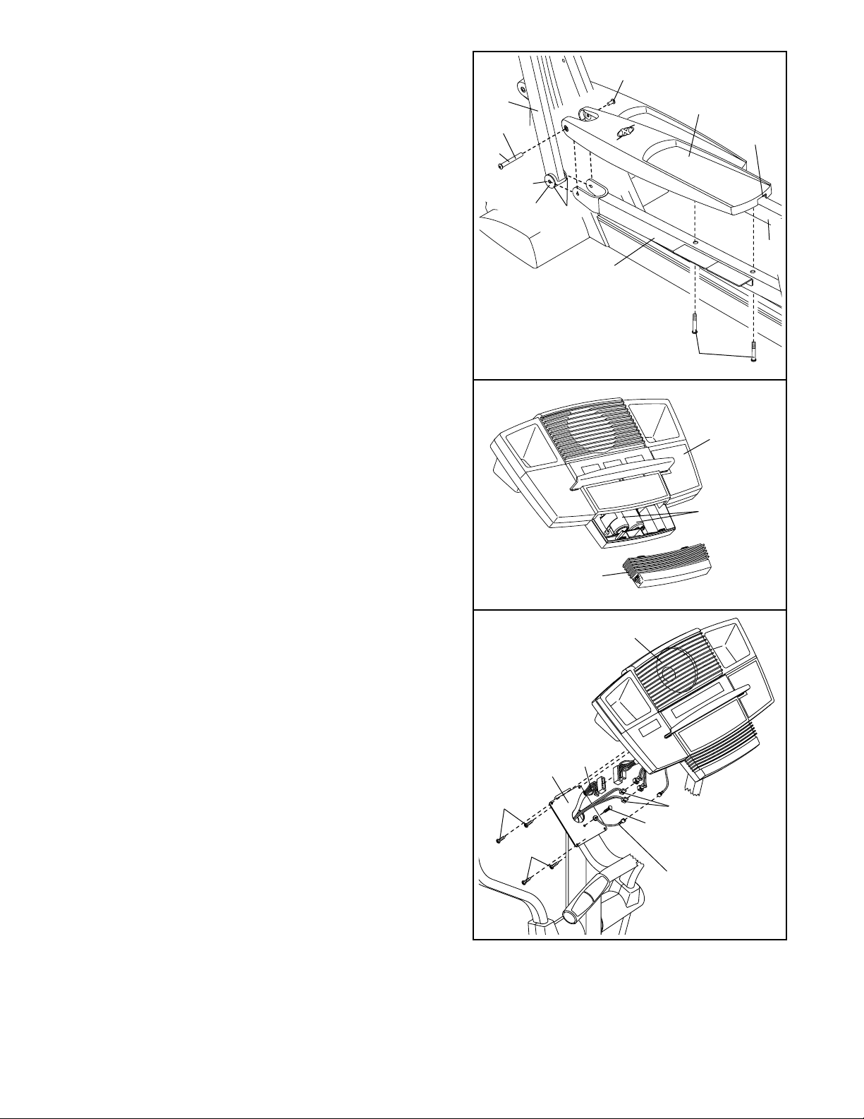
5. Identify the Left Pedal (10), which has a notch near
the right side. Place the Left Pedal on the Left Pedal
Leg (4). Next, apply the entire contents of one of the
included Teflon®lubricant packets to the long side of
an M8 x 79mm Bolt Set (65) and the faces of the two
indicated Upper Body Arm Bushings (12). Have a second person hold the lower end of the left Upper Body
Arm (29) inside of the bracket on the Left Pedal Leg.
Align the indicated holes, and attach the Left Pedal
and the left Upper Body Arm to the Left Pedal Leg with
the M8 x 79mm Bolt Set.
Attach the other end of the Left Pedal (10) to the Left
Pedal Leg (4) with two M8 x 54mm Button Screws (83).
Repeat this step on the right side of the elliptical exerciser.
See step 2. Tighten the two M10 x 108mm Button
Screws (70).
4
10
83
65
5
65
Notch
Lube
29
6. The Console (17) requires four “D” batteries (not
included); alkaline batteries are recommended. Slide
the battery cover off the Console. Insert four batteries
into the battery compartment. Make sure that the bat-
teries are oriented as shown by the diagram inside
the battery compartment. Slide the battery cover
back onto the Console. Note: When the batteries are
installed correctly, the fan will turn on for a moment.
8. Make sure that all parts of the elliptical exerciser are properly tightened. Cover the floor beneath the
elliptical exerciser to protect the floor from damage. Note: Some extra hardware may be left over.
The elliptical exerciser is now fully assembled. If you have purchased the optional chest pulse sensor
(see page 18), see page 7.
6
17
Batteries
Battery
Cover
5
12
Face
Lube
7. Remove the ground wire screw from the Upright (2).
Attach the ground wire to the Upright with the ground
wire screw as shown.
Have another person hold the Console (17) near the
Upright (2). Connect the ground wire to the ground
wire on the Console. Connect the Upper Wire Harness
(30) to the wire harness on the Console. Connect the
two Pulse Wires (20) to the pulse wires on the
Console.
Carefully insert all excess wiring down into the Upright
(2). Attach the Console to the Upright with four M4 x
16mm Screws (94). (Note: The Screws may be found
in the console box.) Be careful to avoid pinching the
wires.
17
2
94
94
30
Do not pinch
the wires
during this step.
7
20
Ground Wire Screw
Ground
Wire
7
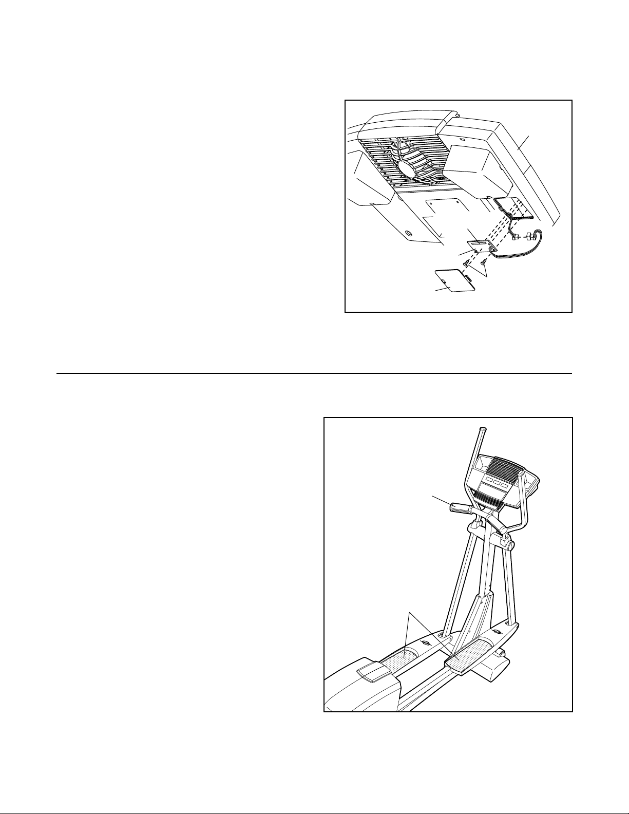
INSTALLING THE RECEIVER FOR THE OPTIONAL CHEST PULSE SENSOR
If you have purchased the optional chest pulse sensor (see page 18), follow the steps below to install the
receiver included with the optional chest pulse sensor.
1. Look under the Console (17) and locate the access
cover. Remove the access cover.
2. Hold the receiver in the position shown, with the small
cylinder oriented as shown. Using the two screws
included with the chest pulse sensor, attach the receiver to the two plastic posts (not shown) inside the
access opening in the back of the Console (17).
3. Connect the wire on the receiver to the indicated wire
on the Console (17). Make sure that the connectors
on the wires snap together. Discard the other wires
included with the chest pulse sensor.
4. Reattach the access cover to the Console (17).
EXERCISING ON THE ELLIPTICAL EXERCISER
To mount the elliptical exerciser, hold the handgrip
pulse sensor and step onto the pedal that is in the
lowest position. Next, step onto the other pedal. Push
the pedals until they begin to move with a continuous
motion.
To dismount the elliptical exerciser, wait until the pedals come to a complete stop. The elliptical exercis-
er does not have a free wheel; the pedals will
continue to move until the flywheel stops. When
the pedals are stationary, step off the highest pedal
first. Then, step off the lowest pedal.
Screws
17
Cylinder
Receiver
Access Cover
HOW TO USE THE ELLIPTICAL EXERCISER
Pedals
Handgrip
Pulse Sensor
8
FEATURES OF THE CONSOLE
The advanced console offers a selection of features
designed to make your workouts more enjoyable and
effective. When the manual mode of the console is
selected, the resistance of the elliptical exerciser can
be changed with the touch of a button. As you exercise, the console will provide continuous exercise
feedback. Y ou can even measure your heart rate using
the handgrip pulse sensor. Note: For information about
an optional chest pulse sensor, see page 18.
The console also offers six resistance and pace programs. Each program automatically changes the resistance of the elliptical exerciser and prompts you to
increase or decrease your pace as it guides you
through an effective workout.
In addition, the console features two heart rate programs that automatically change the resistance of the
elliptical exerciser and prompt you to vary your pace to
keep your heart rate near a target heart rate as you
exercise.
The console also features iFIT.com interactive technology. Having iFIT.com technology is like having a personal trainer in your home. Using the included audio
cable, you can connect the elliptical exerciser to your
home stereo, portable stereo, computer, or VCR and
play special iFIT.com CD and video programs (iFIT.com
CDs and videocassettes are available separately).
iFIT.com CD and video programs automatically control
the resistance of the elliptical exerciser and prompt
you to vary your pace as a personal trainer coaches
you through every step of your workout. High-energy
music provides added motivation. To purchase
iFIT.com CDs and videocassettes, call toll-free
1-800-735-0768.
With the elliptical exerciser connected to your computer, you can also go to our Web site at www.iFIT.com
and access programs directly from the internet.
Explore www.iFIT.com for more information.
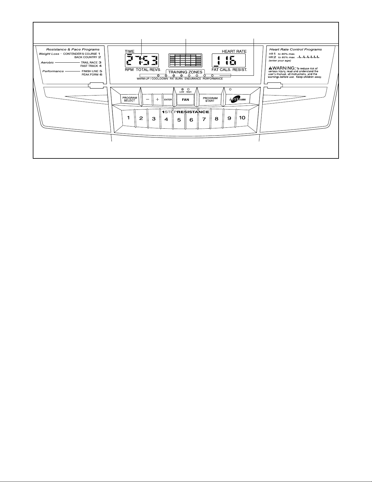
CONSOLE DIAGRAM
Note: If there is a sheet of clear plastic on the face of the console, remove it before using the console.
Matrix
Training Zone Bar
Left Display
 Loading...