

Model No.
Serial No.
The model number and serial number are found in the location shown
below. Write the model number and
serial number in the space above.
Serial
Number
Decal
QUESTIONS?
At FreeMotion Fitness, weʼre
committed to providing complete
customer satisfaction. If you
have questions, see HOW TO
CONTACT CUSTOMER CARE on
page 2 of this manual.
CAUTION
Read all precautions and instructions in this manual before using
this equipment. Keep this manual
for future reference.
SER'S
U
ANUAL
M


TABLE OF CONTENTS
How to Contact Customer Care . . . . . . . . . . . . . . . . . . . . . . . . . . . . . . . . . . . . . . . . . . . . . . . . . . . . .2
SECTION 1
Important Precautions . . . . . . . . . . . . . . . . . . . . . . . . . . . . . . . . . . . . . . . . . . . . . . . . . . . . . . . . . . . . .3
Warning Decal Placement . . . . . . . . . . . . . . . . . . . . . . . . . . . . . . . . . . . . . . . . . . . . . . . . . . . . . . . . . .5
Before You Begin . . . . . . . . . . . . . . . . . . . . . . . . . . . . . . . . . . . . . . . . . . . . . . . . . . . . . . . . . . . . . . . .6
Assembly . . . . . . . . . . . . . . . . . . . . . . . . . . . . . . . . . . . . . . . . . . . . . . . . . . . . . . . . . . . . . . . . . . . . . . .7
How to Move the INCLINE TRAINER . . . . . . . . . . . . . . . . . . . . . . . . . . . . . . . . . . . . . . . . . . . . . . . .11
How to Connect the INCLINE TRAINER . . . . . . . . . . . . . . . . . . . . . . . . . . . . . . . . . . . . . . . . . . . . . .12
SECTION 2
How to Upgrade the Console . . . . . . . . . . . . . . . . . . . . . . . . . . . . . . . . . . . . . . . . . . . . . . . . . . . . . .13
How to Use the Basic Console . . . . . . . . . . . . . . . . . . . . . . . . . . . . . . . . . . . . . . . . . . . . . . . . . . . . .14
SECTION 3
Preventive Maintenance . . . . . . . . . . . . . . . . . . . . . . . . . . . . . . . . . . . . . . . . . . . . . . . . . . . . . . . . . .33
Six-month Preventive Maintenance Record . . . . . . . . . . . . . . . . . . . . . . . . . . . . . . . . . . . . . . . . . . .36
Troubleshooting . . . . . . . . . . . . . . . . . . . . . . . . . . . . . . . . . . . . . . . . . . . . . . . . . . . . . . . . . . . . . . . .37
SECTION 4
Exercise Guidelines . . . . . . . . . . . . . . . . . . . . . . . . . . . . . . . . . . . . . . . . . . . . . . . . . . . . . . . . . . . . .39
SECTION 5
Part List . . . . . . . . . . . . . . . . . . . . . . . . . . . . . . . . . . . . . . . . . . . . . . . . . . . . . . . . . . . . . . . . . . . . . . .43
Exploded Drawing . . . . . . . . . . . . . . . . . . . . . . . . . . . . . . . . . . . . . . . . . . . . . . . . . . . . . . . . . . . . . . .45
FREEMOTION is a registered trademark of ICON IP, Inc.
1

HOW TO CONTACT CUSTOMER CARE
f you have questions after reading this manual, or if you require assistance, please contact Customer Care at the
I
phone number listed below. Please be prepared to give the following information:
• The MODEL NUMBER of the product (see the front cover of this manual for the location).
• The NAME of the product (FREEMOTION INCLINE TRAINER).
• The SERIAL NUMBER of the product (see the front cover of this manual for the location).
Customer Care: 1-800-201-2109, Monday–Friday, 7 a.m.–6 p.m. Mountain Time
FreeMotion Fitness, Inc.
2

IMPORTANT PRECAUTIONS
WARNING: To reduce the risk of burns, fire, electric shock, or injury to persons, read the
ollowing important precautions and information before operating the INCLINE TRAINER.
f
1. It is the responsibility of the owner to ensure
hat all users of the INCLINE TRAINER are ad-
t
equately informed of all warnings and precautions.
2. Use the INCLINE TRAINER only as described
in this manual.
3. Place the INCLINE TRAINER on a level sur-
face, with at least 2.5 m (8 ft.) of clearance behind it and 0.5 m (2 ft.) on each side. Do not
place the INCLINE TRAINER on a surface that
blocks any air openings. To protect the floor
or carpet from damage, place a mat under the
INCLINE TRAINER.
4. Keep the INCLINE TRAINER indoors, away
from moisture and dust. Do not place the INCLINE TRAINER in a garage or covered patio,
or near water.
5. Do not operate the INCLINE TRAINER where
aerosol products are used or where oxygen is
being administered.
6. Do not operate the INCLINE TRAINER until it
is properly and fully assembled (see ASSEMBLY on page 7).
7. Regularly inspect and tighten all parts of the
INCLINE TRAINER.
8. Keep children under the age of 12 and pets
away from the INCLINE TRAINER at all times.
9. The INCLINE TRAINER should not be used by
persons weighing more than 160 kg (350 lbs).
10. Never allow more than one person on the
INCLINE TRAINER at a time.
11. Wear appropriate exercise clothes when
using the INCLINE TRAINER. Do not wear
loose clothes that could become caught in
the INCLINE TRAINER. Athletic support
clothes are recommended for both men and
women. Always wear athletic shoes. Never
use the INCLINE TRAINER with bare feet,
wearing only stockings, or in sandals.
12. When connecting the power cord, follow the intructions on page 12. No other appliance
s
should be on the same circuit as the INCLINE
TRAINER. Do not use an extension cord.
13. Keep the power cord away from heated sur-
faces.
14. Never move the walking belt while the power
is turned off. Do not operate the INCLINE
TRAINER if the power cord or plug is damaged or if the INCLINE TRAINER is not working properly. (See BEFORE YOU BEGIN on
page 6 if the INCLINE TRAINER is not working
properly.)
15. Read, understand, and test the emergency
stop procedure before using the INCLINE
TRAINER (see GETTING STARTED on page
17).
16. Never start the INCLINE TRAINER while you
are standing on the walking belt. Always hold
the handrails while using the INCLINE
TRAINER.
17. The INCLINE TRAINER is capable of high
speeds. Adjust the speed in small increments
to avoid sudden jumps in speed.
18. The pulse sensor is not a medical device.
Various factors, including the user's movement, may affect the accuracy of heart rate
readings. The pulse sensor is intended only
as an exercise aid in determining heart rate
trends in general.
19. Never leave the INCLINE TRAINER unat-
tended while it is running.
20. Do not change the incline of the INCLINE
TRAINER by placing objects under it.
21. Never insert or drop any object into any
opening.
22. Make sure to perform all maintenance proce-
dures outlined in this manual. Failure to do so
will void the warranty and may result in damage to the INCLINE TRAINER.
3

23. DANGER: Always unplug the power
cord before cleaning the INCLINE TRAINER
and before performing the maintenance and
djustment procedures described in this man-
a
ual. Servicing other than the procedures in
this manual should be performed by an authorized service representative only.
WARNING: Before beginning this or any exercise program, consult your physician. This
is especially important for persons over the age of 35 or persons with pre-existing health problems.
Read all instructions before using. FreeMotion Fitness assumes no responsibility for personal injury
or property damage sustained by or through the use of this product.
SAVE THESE INSTRUCTIONS
4

HAZARDOUS
VOLTAGE
Disconnect power
before servicing.
Do not remove or insert this plug while the
safety key is inserted in the console. Touch
metal frame before removing or inserting plug.
Static sensitive components may be affected.
WARNING
!
:
HIGH VOLTAGE
Disconnect line cord from
outlet before servicing.
:
HIGH VOLTAGE
Disconnect line cord from
outlet before servicing.
WARNING DECAL PLACEMENT
he decals shown below have been placed on the INCLINE TRAINER. If a decal is missing, or if it is not
T
legible, see HOW TO CONTACT CUSTOMER CARE on page 2 of this manual and order a free replacement
decal. Note: The decals may not be shown at actual size.
Note: There
is one decal
on each side.
5

BEFORE YOU BEGIN
Congratulations for selecting the revolutionary
FREEMOTION®INCLINE TRAINER. The INCLINE
TRAINER offers an impressive array of features to
ake your workouts more effective and enjoyable.
m
For your benefit, read this manual carefully before
you use the INCLINE TRAINER. If you have ques-
tions after reading this manual, see HOW TO CONTACT CUSTOMER CARE on page 2 of this manual.
Handgrip Pulse Sensor
Accessory Tray
Handrail
To help us assist you, please note the model number
and serial number of the INCLINE TRAINER before
calling. The model number and serial number can be
ound on a decal attached to the INCLINE TRAINER
f
(see the front cover of this manual for the location of
the decal).
Before reading further, please familiarize yourself with
the parts that are labeled in the drawing below.
Console
Key/Clip
Cushioned Walking Platform
Walking Belt
Foot Rail
Roller Adjustment Bolts
On/off Circuit Breaker
Power Cord
6

Console Plate Screw
(94)–4*
Display Mounting Screw
(114)–5*
*These Screws are included only with the Workout TV console INCLINE TRAINER.
1/2” Star
Washer (124)–4
Side Base Bolt (95)–4
Top Base Bolt (96)–4
ASSEMBLY
Assembly requires two persons. Set the INCLINE TRAINER in a cleared area and remove all packing materials.
Do not dispose of the packing materials until assembly is completed. Assembly can be completed using a 3/8”
ex key, a 7/32” hex key, and a Phillips screwdriver.
h
For help identifying assembly hardware, see the drawings below. Note: If a part is not found in the part bags,
check to see if the part has been preattached. To avoid damaging plastic parts, do not use power tools for
assembly.
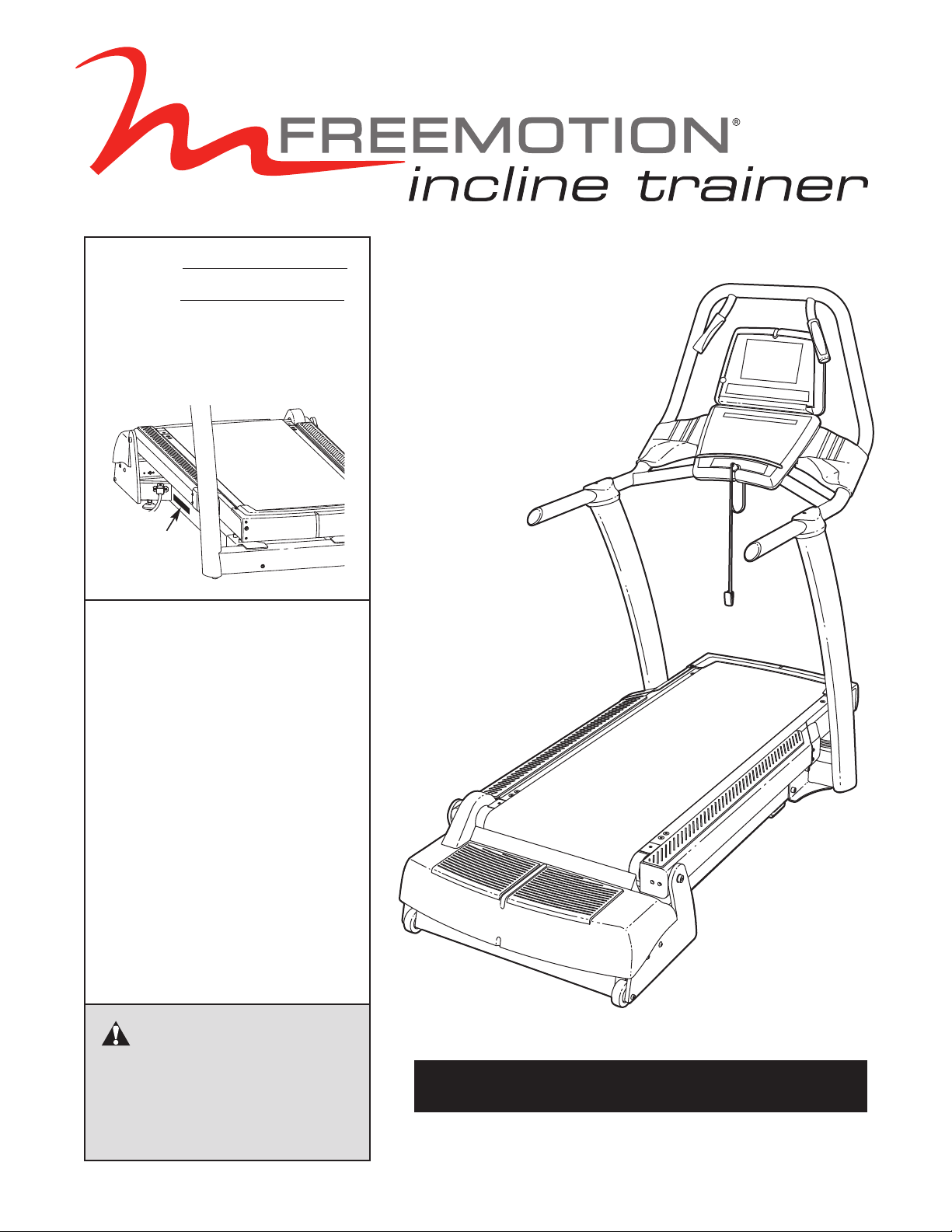
1. Place the Uprights (93) near the front of the Base Frame
(56) as shown.
Connect the indicated wires on the right side of the INCLINE TRAINER. See the inset drawing. The connec-
tors should slide together easily and snap into place.
If they do not, turn one connector and try again. IF THE
CONNECTORS ARE NOT INSERTED PROPERLY, THE
CONSOLE MAY BE DAMAGED WHEN THE POWER IS
TURNED ON.
Insert the excess wire into the indicated hole in the
Upright (93).
1
93
Hole
LEFT
7
RIGHT
Wires
56
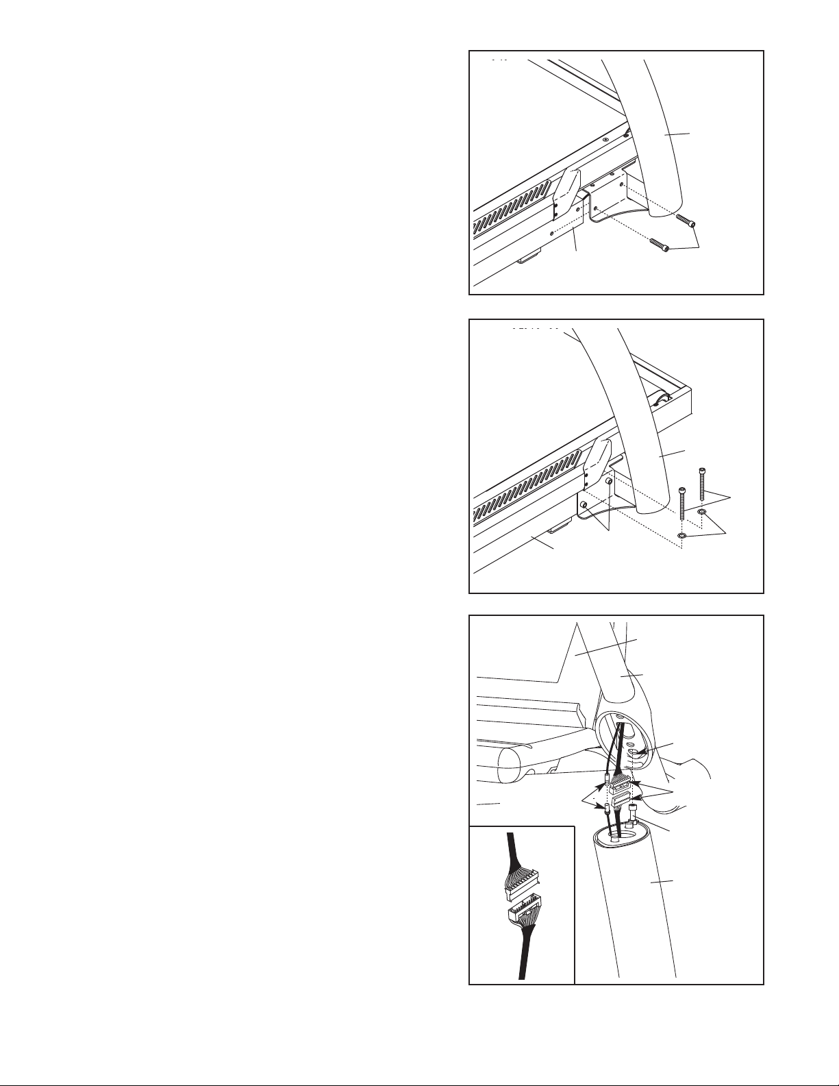
2. Slide the Uprights (93) onto the Base Frame (56), and
align the holes in the Uprights with the holes in the Base
Frame. Be careful to avoid pinching the wires. Finger
ighten two Side Base Bolts (95) through the bracket near
t
the right Upright and into the Base Frame; do not
ighten the Side Base Bolts yet.
t
Repeat this step on the left side of the INCLINE
TRAINER; there are no wires on the left side.
2
93
3. Finger tighten two Top Base Bolts (96) with two 1/2" Star
Washers (124) through the top of the bracket near the
right Upright (93) and into the Base Frame (56); do not
tighten the Top Base Bolts yet.
Repeat this step on the left side of the INCLINE
TRAINER.
Then, tighten the Top Base Bolts (96) and the Side Base
Bolts (95) on both sides.
4. Locate the Bolt (B) on the top of each Upright (93). With
the help of a second person, set the console assembly
onto the top of the Uprights. Make sure that the Bolts
are inserted into the indicated holes in the bottom of
the console assembly (only one side is shown). Be
careful not to pinch any wires. Pull up on the Handrail
(103) and carefully tip the console assembly forward so
that you can see the indicated wires. Make sure the con-
sole assembly is held securely by the Bolts.
56
3
95
56
4
Console
Assembly
103
95
93
96
124
Hole
Connect the wire in the right Upright (93) and the wire in
the console assembly. See the inset drawing. The con-
nectors should slide together easily and snap into
place. If they do not, turn one connector and try again. IF
THE CONNECTORS ARE NOT INSERTED PROPERLY, THE CONSOLE MAY BE DAMAGED WHEN
THE POWER IS TURNED ON. If there is a TV Cable,
connect the TV Cable in the console assembly to the TV
Cable in the right Upright. Then, insert the wires down
into the right Upright.
8
TV Cables
Wires
B
93
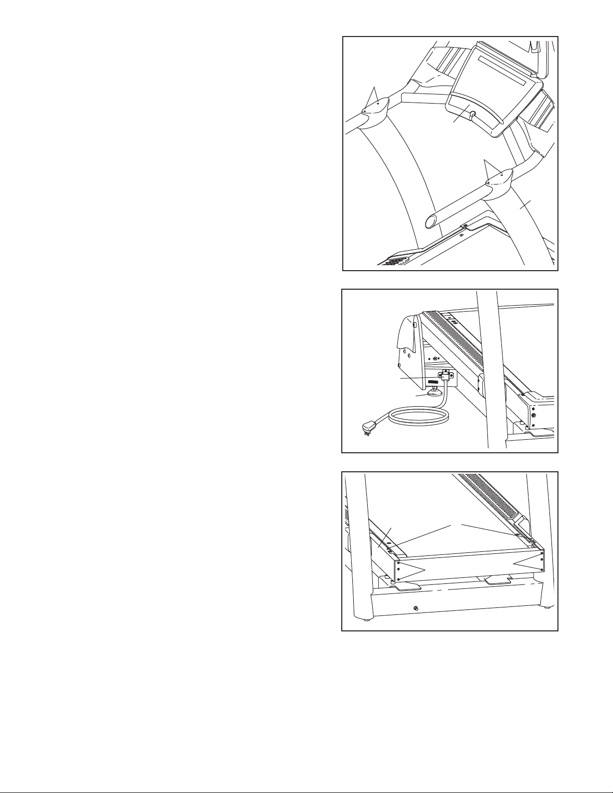
5. With the help of a second person, pivot the console assembly to the position shown. Be careful to avoid pinch-
ing your hands or the wires.
5
Align the Handrail Bolts (102) with the holes in the tops of
he Uprights (93). Start all four Handrail Bolts, and then
t
firmly tighten them.
6. After the INCLINE TRAINER is placed in the location
where it will be used (see HOW TO MOVE THE INCLINE TRAINER on page 11), make sure that both
Rear Feet (38) and the Base Pads (not shown) rest
firmly on the floor. If the INCLINE TRAINER rocks even
slightly, turn the right Rear Foot clockwise or counterclockwise until the rocking motion is eliminated.
Note: The Power Cord Bracket (64) must be attached at all times.
102
Console
ssembly
A
102
93
6
64
38
7. Remove the two Cover Screws (2) and the four Front
Cover Screws (16) from the Frame (22).
7
22
16
2
16
9
8. Attach the Front Cover (17) to the Frame (22) with the
two Cover Screws (2) and the four Front Cover Screws
(16).
8
22
2
16
17
9. Make sure that all parts are properly tightened before you use the INCLINE TRAINER. To protect the
floor or carpet, place a mat beneath the INCLINE TRAINER.
If you purchase the Workout TV console, follow the steps below to assemble the console.
1. Unplug the power cord. Remove the five Display
Mounting Screws (114) from the back of the Basic
Console (not shown), and remove the Basic Console
from the treadmill. Disconnect all wires connecting the
Basic Console to the treadmill.
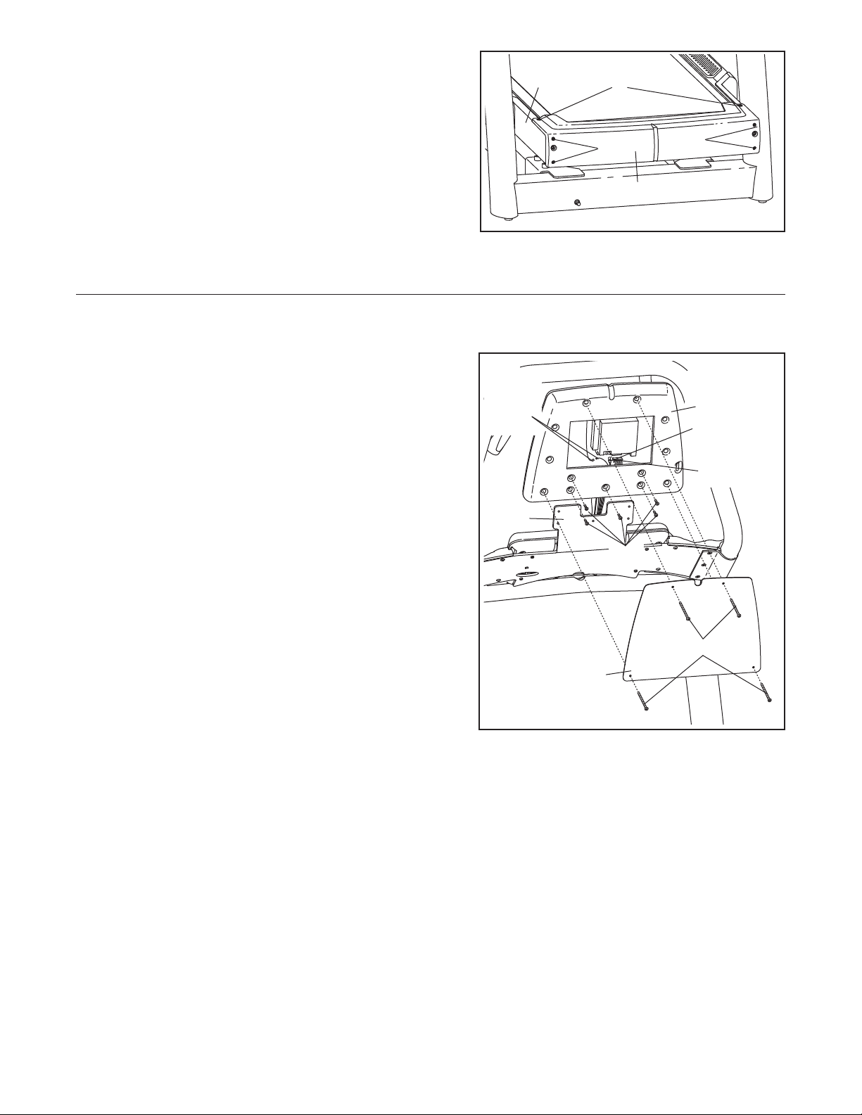
2. Insert the wire harness, the TV cable, and the ground
wire into the bottom of the TV Console Assembly (A) as
you slide the TV Console Assembly onto the bracket on
the Handrail (103). Connect the wire harness, the TV
cable, and the ground wire to the back of the TV
Console Assembly. Make sure to connect the con-
nectors properly.
6
Ground
Wires
103
114
16
A
TV Cable
Wire
Harness
Align the indicated five holes in the back of the TV
Console Assembly (A) with the five holes in the bracket
on the Handrail (103). Attach the TV Console Assembly
with five Display Mounting Screws (114). Be careful
not to pinch any wires.
Attach the TV Console Plate (118) to the TV Console
Assembly (A) with four Console Plate Screws (94).
94
118
10
HOW TO MOVE THE INCLINE TRAINER
Before moving the INCLINE TRAINER, unplug the
power cord. Note: It may be necessary to disconnect a
CATV cable and a network wire from the INCLINE
TRAINER, depending on how far the INCLINE
RAINER will be moved.
T
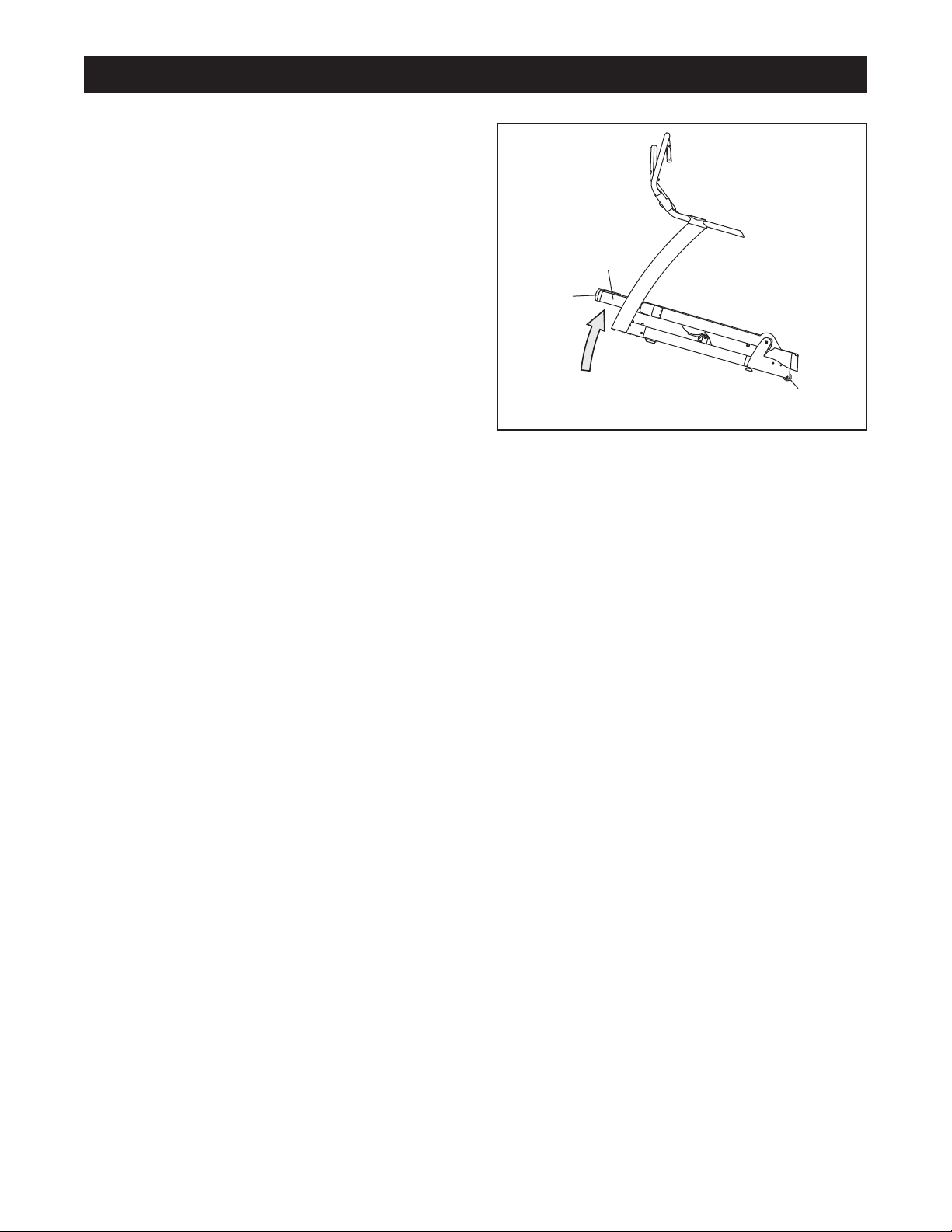
Due to the size and weight of the INCLINE TRAINER,
moving it requires two or three persons. Hold the
metal frame firmly in the location shown at the right.
CAUTION: To decrease the possibility of damage to
the INCLINE TRAINER or of injury, do not lift the
frame by the plastic front cover. Carefully roll the IN-
CLINE TRAINER on the wheels to the desired location
and then lower it back to the level position. CAUTION: To
reduce the risk of injury, use extreme caution while
moving the INCLINE TRAINER. Do not attempt to
move the INCLINE TRAINER over uneven surfaces.
Cover
Frame
Front
Wheels
11
HOW TO CONNECT THE INCLINE TRAINER
HOW TO CONNECT THE POWER CORD IN THE UK
DANGER: Improper connection
his product must be earthed. If it should malfunc-
of the equipment-grounding conductor can
esult in an increased risk of electric shock.
r
Check with a qualified electrician or serviceman if you are in doubt as to whether the
product is properly grounded. Do not modify
the plug provided with the product—if it will
not fit the outlet, have a proper outlet
installed by a qualified electrician. Do not use
an adapter to connect the plug to an improper
receptacle.
HOW TO CONNECT THE POWER CORD IN THE
UNITED STATES
This product must be grounded. If it should malfunc-
tion or break down, grounding provides a path of least
resistance for electric current to reduce the risk of electric shock.
T
tion or break down, earthing provides a path of least
resistance for electric current to reduce the risk of electric shock.
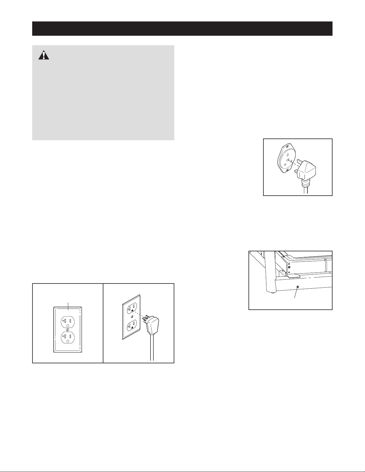
This product is for use on a dedicated, 10-amp,
240-volt circuit. No other appliance should be on
the same circuit. The product is equipped with a cord
having an equipment-earthing conductor and an earthing plug.
Plug the earthing plug
into a receptacle as
shown at the right. Do
not modify the plug or
the receptacle. Do not
use an adapter or an extension cord. The receptacle must be earthed.
This product is for use on a dedicated, 20-amp,
120-volt circuit. No other appliance should be on
the same circuit. This product is equipped with a cord
having an equipment-grounding conductor and a
grounding plug.
Plug the grounding plug into a standard NEMA 5-20
receptacle. Do not modify the plug or the receptacle.
Do not use an adapter, a surge protector, or an extension cord. The receptacle must be grounded.
NEMA 5-20
Receptacle
HOW TO CONNECT A CATV CABLE
If your INCLINE TRAINER has the Workout TV console, a CATV cable must be connected to the IN-
CLINE TRAINER for cable TV stations to be viewed.
Locate the cable
jack on the front of
the INCLINE
TRAINER.
Connect the CATV
cable to the cable
jack (in the UK use
a PAL adapter [not
included]). Route
the cable so that it
will not be pinched or crushed by the lift mechanism or
the frame.
A satellite receiver, VCR, or DVD player can also be
connected to the INCLINE TRAINER. Connect a CATV
cable from the coaxial output on your equipment (usually labeled TV OUT or RF OUT) to the cable jack on
the front of the INCLINE TRAINER.
Cable Jack
Note: Audio/video equipment without coaxial outputs
(some satellite receivers and DVD players) will require
an RF modulator to work correctly. RF modulators are
not available from FreeMotion Fitness, but are available at electronics stores. See the owner's manual for
the equipment you wish to connect to determine if an
RF modulator is needed, or contact your local
audio/visual service provider.
12

HOW TO UPGRADE THE CONSOLE
Your INCLINE TRAINER has been pre-configured to
operate with the Basic console or the Workout TV con-
ole (see the drawings below). To upgrade your con-
s
sole and expand the capabilities of your INCLINE
Basic Console
TRAINER whenever you choose, see HOW TO
CONTACT CUSTOMER CARE on page 2 of this
anual.
m
Workout TV Console
13

HOW TO USE THE BASIC CONSOLE
atrix
M
Main Display
Note: If there is a
sheet of clear
plastic on the face
f the console,
o
remove it.
FEATURES OF THE CONSOLE
The Basic console offers an impressive array of features designed to help you get the greatest benefits
from your exercise.
When the QUICK START mode is selected, the speed
and incline of the INCLINE TRAINER can be changed
with the touch of a button. As you exercise, the console
will provide continuous exercise feedback. You can
even measure your heart rate using the built-in pulse
sensor.
In addition, the console offers a wide selection of workout programs. Each program automatically controls the
speed and/or incline of the INCLINE TRAINER to give
you an effective workout.
The console also offers three HEART RATE programs
that adjust the speed and incline of the INCLINE
TRAINER to keep your heart rate near target levels
during your workouts, and three unique FITNESS
TEST programs that measure your relative fitness
level. Note: The HEART RATE programs and the FITNESS TEST programs require the use of a Polar
patible chest pulse sensor (not included).
Before using the INCLINE TRAINER, please read
OVERVIEW OF THE CONSOLE beginning on page
15. To use the QUICK START mode of the console,
follow the steps beginning on page 17. To use a MAN-
UAL program, see page 18. To use a FITNESS TEST
program, see page 20. To use a HEART RATE program, see page 22. To use an INTERVAL program,
see page 24. To use a WALK/RUN program, see
page 26. To use a TERRAIN program, see page 27.
To use a FITNESS or RANDOM program, see page
28. To use a CUSTOM program, see page 29. To
use the maintenance mode, see page 30.
®
-com-
14
VERVIEW OF THE CONSOLE
O
For your benefit, please read all of the instructions
on pages 15 and 16 before you use the INCLINE
TRAINER.
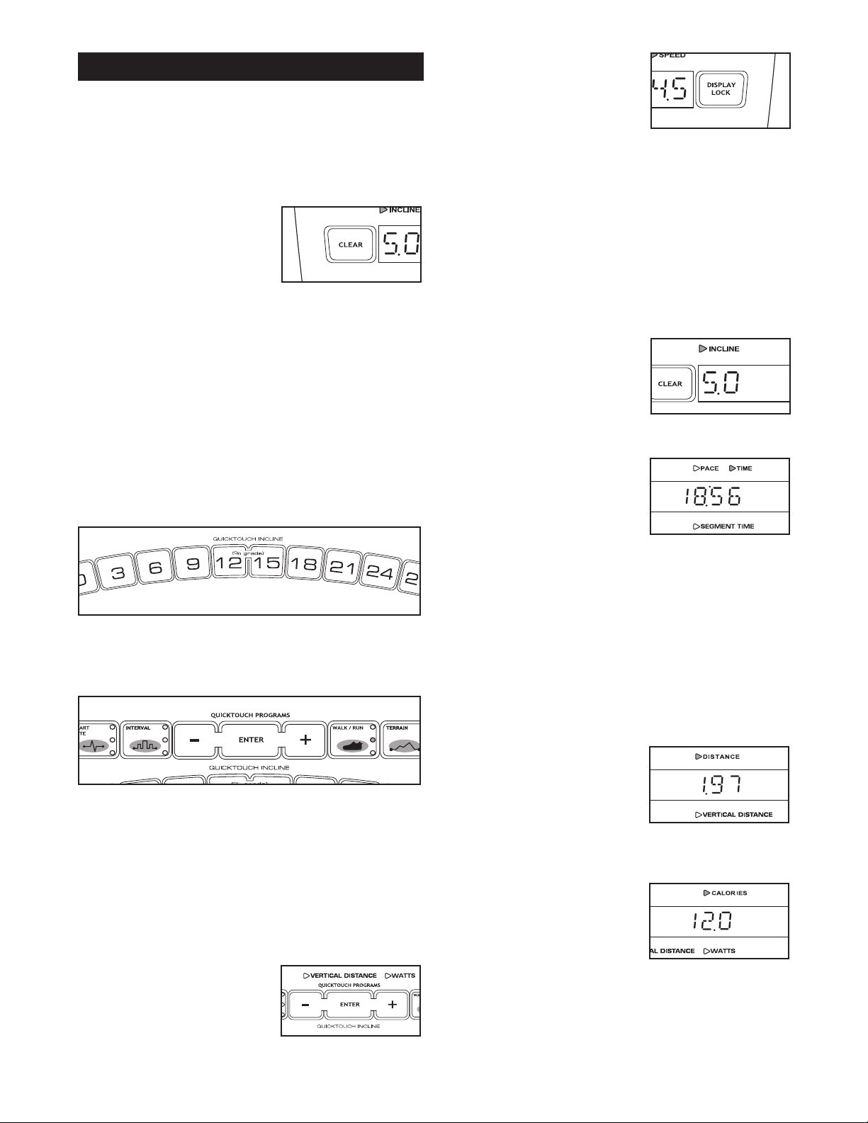
THE BUTTONS
The CLEAR button—This
button is used to reset the
console. When this button is
pressed, the main display
will be reset and the words
SELECT PROGRAM TO
BEGIN will appear in the main display. Note: If one
program is started and then a different program is selected, the main display will not be reset unless the
CLEAR button is pressed before the second program
is selected.
The QUICKTOUCH INCLINE buttons—These buttons control the incline of the walking belt. To change
the incline quickly, press the QUICKTOUCH INCLINE
buttons. Note: After the buttons are pressed, it may
take a moment for the INCLINE TRAINER to reach the
selected incline setting.
The QUICKTOUCH PROGRAMS buttons—These
buttons are used to select the various programs.
The DISPLAY LOCK
button—This button can be
used during your workout to
eep the main display from
k
scanning from one number to
he next every few seconds.
t
Each time the DISPLAY LOCK button is pressed during your workout, the word LOCKED or UNLOCKED
will briefly appear in the main display.
THE MAIN DISPLAY
The main display will display a variety of text messages
to guide you through your workouts. In addition, the
main display will display the following information while
you exercise:
Incline—The left end of the
main display will show the incline setting of the INCLINE
TRAINER.
Pace/Time/Segment
Time—When the QUICK
START mode, the MANUAL
VERTICAL DISTANCE program, the MANUAL
CALORIE program, or any of
the WALK/RUN programs are selected, this section of
the main display will show your pace, in minutes per
mile or minutes per kilometer, the elapsed time, and the
elapsed time in the current segment. The display will
change from one number to the next every few seconds. When any other program is selected, the main
display will show your pace, the time remaining in the
program, and the time remaining in the current segment
of the program. The display will change from one number to the other every few seconds.
The COOL DOWN button—This button is designed to
help you cool down after a workout. When you press
the COOL DOWN button, the speed of the walking belt
will automatically adjust to 3 mph (or 5 kph) and the incline will adjust to 0% for a three-minute cool-down
walk. Note: If the walking belt is already moving at less
than 3 mph (or 5 kph), the speed of the walking belt
will not change.
The ENTER button and +
and – buttons—These but-
tons are used to enter information into the console.
Distance/Vertical
Distance—This section of
the main display will show
the distance that you have
walked or run, in miles or
kilometers, and the number
of vertical feet you have climbed.
Calories/Watts—This section of the main display will
show the approximate number of calories you have
burned and your power output in watts. The display will
change from one number to the other every few seconds.
15

Pulse/% Max—When you
se the handgrip pulse sen-
u
sor or a Polar
chest pulse sensor (not included), this section of the
main display will show your
heart rate. When a HEART RATE program is selected,
he display will show your heart rate and the corre-
t
sponding percentage of your age-predicted maximum
heart rate (see step 7 on page 22 for an explanation of
your age-predicted maximum heart rate). The display
will change from one number to the other every few
seconds. Note: The display will only show the percentage of your age-predicted maximum heart rate if you
have entered your age.
Speed—The right end of
the main display will show
the speed of the walking
belt, in miles per hour or
kilometers per hour.
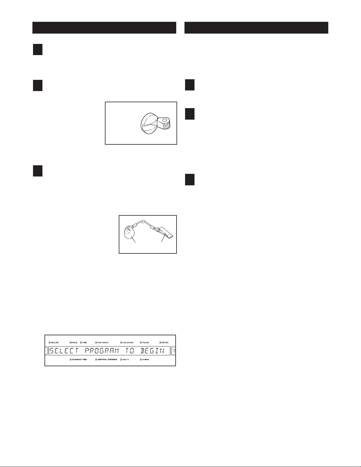
THE PULSE SENSOR
If there are sheets of
clear plastic on the
metal contacts on the
pulse sensor, peel off
the plastic. To mea-
sure your heart rate,
stand on the foot rails
and hold the contacts
with both hands; your
palms must be resting on the upper contacts, and your
fingers must be touching the lower contacts. Avoid
moving your hands. When your pulse is detected, the
PULSE indicator above the main display will begin to
flash, and then your heart rate will be shown. For the
most accurate heart rate reading, hold the contacts for
at least 15 seconds without moving your hands.
®
-compatible
Contacts
CAUTION: Before operating the
console, read the following precautions.
Do not stand on the walking belt when turn-
•
ing on the power.
Always wear the clip (see the drawing on
•
page 17) while operating the INCLINE
RAINER.
T
• Adjust the speed in small increments to
avoid sudden jumps in speed.
• The pulse sensor is not a medical device.
Various factors may affect the accuracy of
heart rate readings. The pulse sensor is intended only as an exercise aid in determining heart rate trends in general.
• If you have heart problems, or if you are over
60 years of age and have been inactive, do
not use the HEART RATE or FITNESS TEST
programs. If you are taking medication regularly, consult your physician to find whether
the medication will affect your exercise heart
rate.
• To reduce the possibility of electric shock,
keep the console dry. Avoid spilling liquids
on the console and place only a sealed water
bottle in the water bottle holder.
If your heart rate is not shown, make sure that your
hands are positioned as described. Be careful not to
move your hands excessively or to squeeze the contacts too tightly. For optimal performance, clean the
contacts using a soft cloth; never use alcohol, abrasives, or chemicals.
16
ETTING STARTED
G
OW TO USE THE QUICK START MODE
H
Plug in the power cord.
1
See HOW TO CONNECT THE POWER CORD on
page 12.
Move the on/off circuit breaker to the “on”
2
position.
Locate the on/off
circuit breaker on
the INCLINE
TRAINER near
the power cord.
Switch the on/off
circuit breaker to
the “on” position.
Insert the key into the console.
“On”
Position
3
Note: The console can be set to be used without
the key. See page 32 for instructions. If the console has been set to be used without the key, this
step does not apply.
Find the key and the clip
on the console and attach the clip to the waistband of your clothes.
Next, insert the key into
the console. Important:
In an emergency situation, the key can be pulled from the console,
causing the walking belt to slow to a stop. Test
the clip by carefully taking a few steps backward; if the key is not pulled from the console,
adjust the position of the clip.
Insert the key into the console again. After a moment, various displays and indicators on the console will light.
Key
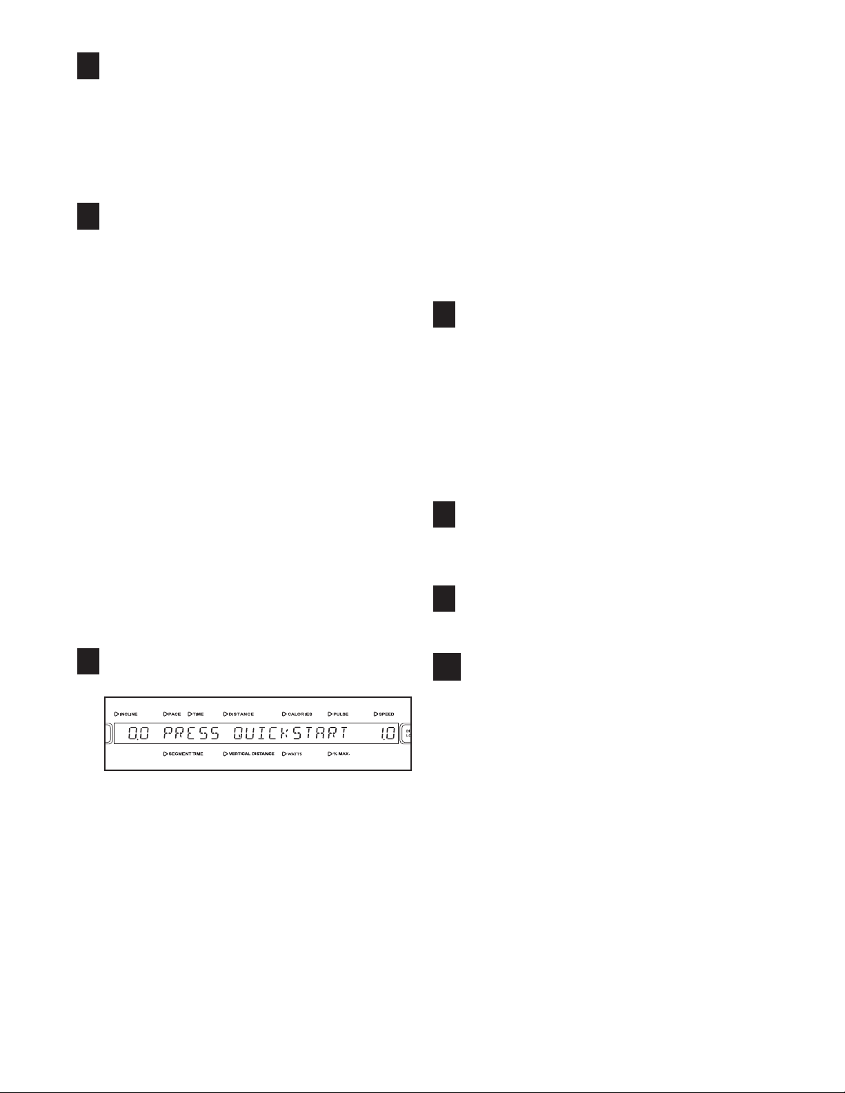
If you do not plan to use a program, the QUICK
START mode will allow you to simply start exercising
and adjust the speed and incline of the INCLINE
TRAINER manually.
Insert the key into the console.
1
See GETTING STARTED at the left.
Select the QUICK START mode.
2
To select the QUICK START mode, press the
QUICK START button.
A moment after the button is pressed, the walking
belt will begin to move at 1 mph. Hold the
handrails and begin walking.
Change the speed and incline as desired.
3
As you exercise, change the speed of the walking
belt as desired by pressing the SPEED + and –
buttons. Each time a button is pressed, the speed
setting will change by 0.1 mph; if a button is held
down, the speed setting will change in rapid increments. Note: After the buttons are pressed, it may
take a moment for the INCLINE TRAINER to
reach the selected speed setting.
Clip
To change the incline of the INCLINE TRAINER,
press the INCLINE + and – buttons. Each time a
button is pressed, the incline will change by 0.5%.
Note: After the buttons are pressed, it may take a
moment for the INCLINE TRAINER to reach the
selected incline setting.
To change the incline quickly, press the QUICKTOUCH INCLINE buttons. Note: After the buttons
are pressed, it may take a moment for the INCLINE TRAINER to reach the selected incline setting.
17
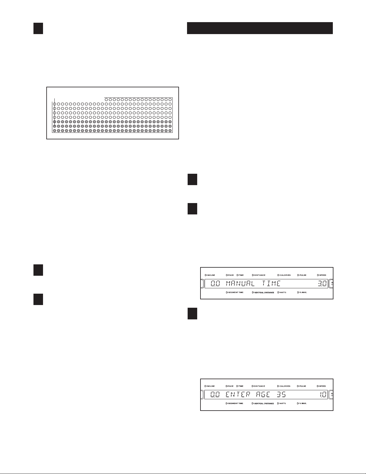
ollow your progress with the matrix and the
F
4
main display.
OW TO USE A MANUAL PROGRAM
H
The matrix will show your progress and the incline
ettings that you select. When you begin exercis-
s
ing, the left column of the matrix will begin to flash.
After 30 seconds, a tone will sound and the column to the right will begin to flash.
Flashing Column
Each time you change the incline of the walking
belt, additional indicators will light or darken in the
flashing column, and in all columns to the right of
the flashing column.
After every 30 seconds that you exercise, a tone
will sound and the next column to the right will
begin to flash. When you have exercised for 7 1/2
minutes, the same column will continue to flash,
and all columns of indicators will shift one position
to the left. The columns of indicators will continue
to shift to the left after every 30 seconds, until you
are finished exercising.
See THE MAIN DISPLAY on page 15.
The MANUAL TIME program allows you to enter a
time goal for your workout. The program will then
count down the time remaining in your workout as you
control the speed and incline of the INCLINE
TRAINER.
The MANUAL VERTICAL DISTANCE program allows
you to enter a vertical distance goal for your workout.
The program will calculate the vertical distance you
have walked or run in your workout as you control the
speed and incline of the INCLINE TRAINER.
The MANUAL CALORIE program allows you to enter a
calorie-burning goal for your workout. The program
calculates the calories you have burned in your workout as you control the speed and incline of the INCLINE TRAINER.
Insert the key into the console.
1
See GETTING STARTED on page 17.
Select a MANUAL program.
2
Press the MANUAL button one, two, or three
times to select the MANUAL TIME, MANUAL
VERTICAL DISTANCE, or MANUAL CALORIE
program. The name of the program will appear in
the main display. The words ENTER AGE and the
current age setting will then be shown.
Measure your heart rate if desired.
5
See THE PULSE SENSOR on page 16.
When you are finished exercising, stop the
6
walking belt and remove the key.
Step onto the foot rails and press the STOP
button. Next, remove the key from the console and
put the key in a secure place.
When the INCLINE TRAINER is not in use, switch
the on/off circuit breaker near the power cord to
the off position and unplug the power cord.
Enter your age.
3
A moment after the program is selected, the
words ENTER AGE and an age setting of 35 will
appear in the main display. To enter your age,
press the + and – buttons beside the ENTER button; hold down the buttons to enter your age
quickly. When your age is shown, press the
ENTER button.
18
Enter your weight.
4
Next, the words ENTER WEIGHT and a weight
setting of 185 pounds will appear in the main display. To enter your weight, press the + and – but-
ons beside the ENTER button; hold down the
t
buttons to enter your weight quickly. When your
eight is shown, press the ENTER button.
w
As you exercise, change the speed of the walking
belt as desired by pressing the SPEED + and –
buttons. Each time a button is pressed, the speed
etting will change by 0.1 mph; if a button is held
s
down, the speed setting will change in rapid incre-
ents. Note: After the buttons are pressed, it may
m
take a moment for the INCLINE TRAINER to
reach the selected speed setting.
Enter a program goal.
5
If you have selected the MANUAL TIME program,
the words ENTER TIME and a time setting of 15
minutes will appear in the main display. To
change the length of time that the program will
last, press the + and – buttons beside the ENTER
button. Then, press the ENTER button.
If you have selected the MANUAL VERTICAL
DISTANCE program, the words ENTER VERTICAL DISTANCE and a vertical distance setting of
500 feet will appear in the main display. To
change the vertical feet you want to walk or run
during your workout, press the + and – buttons
beside the ENTER button. Then, press the
ENTER button.
If you have selected the MANUAL CALORIE program, the words ENTER CALORIES and a calorie-burning goal setting of 100 calories will appear
in the main display. To change the approximate
number of calories that you want to burn during
your workout, press the + and – buttons beside
the ENTER button. Then, press the ENTER button.
To stop the walking belt, press the STOP button.
The time will begin to flash in the main display. To
restart the walking belt, press the QUICK START
button or the SPEED + button and then adjust the
speed as desired.
Change the incline of the INCLINE TRAINER as
7
desired.
To change the incline of the INCLINE TRAINER,
press the INCLINE + and – buttons. Each time a
button is pressed, the incline will change by 0.5%.
To change the incline quickly, press the QUICKTOUCH INCLINE buttons. Note: After the buttons
are pressed, it may take a moment for the INCLINE TRAINER to reach the selected incline setting.
Follow your progress with the matrix and the
8
main display.
See step 4 on page 18.
Measure your heart rate if desired.
9
See THE PULSE SENSOR on page 16.
Press the QUICK START button to start the
6
program.
A moment after the button is pressed, the walking
belt will begin to move at 1 mph. Hold the handrails
and begin walking.
19
When the program is completed, remove the
10
key.
Step onto the foot rails. Remove the key from the
console and put the key in a secure place.
When the INCLINE TRAINER is not in use, switch
the on/off circuit breaker near the power cord to
the off position and unplug the power cord.
OW TO USE A FITNESS TEST PROGRAM
H
The FITNESS TEST programs measure your approximate VO
measure of your ability to take in and utilize oxygen to
generate energy for endurance activities such as run-
ing and cycling. In technical terms, VO
n
maximum volume of oxygen, in milliliters, that your
body can use in one minute, per kilogram of body
weight. A high VO
diorespiratory fitness. Note: To learn more about VO
max, refer to a reputable book or consult your physician.
For the most accurate results, use a FITNESS TEST
program when you are not feeling tired, when you have
not eaten for at least two hours, and when you have not
exercised for at least 24 hours.
The GERKIN FITNESS TEST is completed when your
heart rate stays greater than 85% of your age-predicted
maximum heart rate for 15 seconds, or when the program reaches 11 minutes. Note: The GERKIN FITNESS TEST begins with a 3-minute warm-up.
max, or aerobic capacity. VO2max is a
2
ax is the
m
2
max indicates a high level of car-
2
2
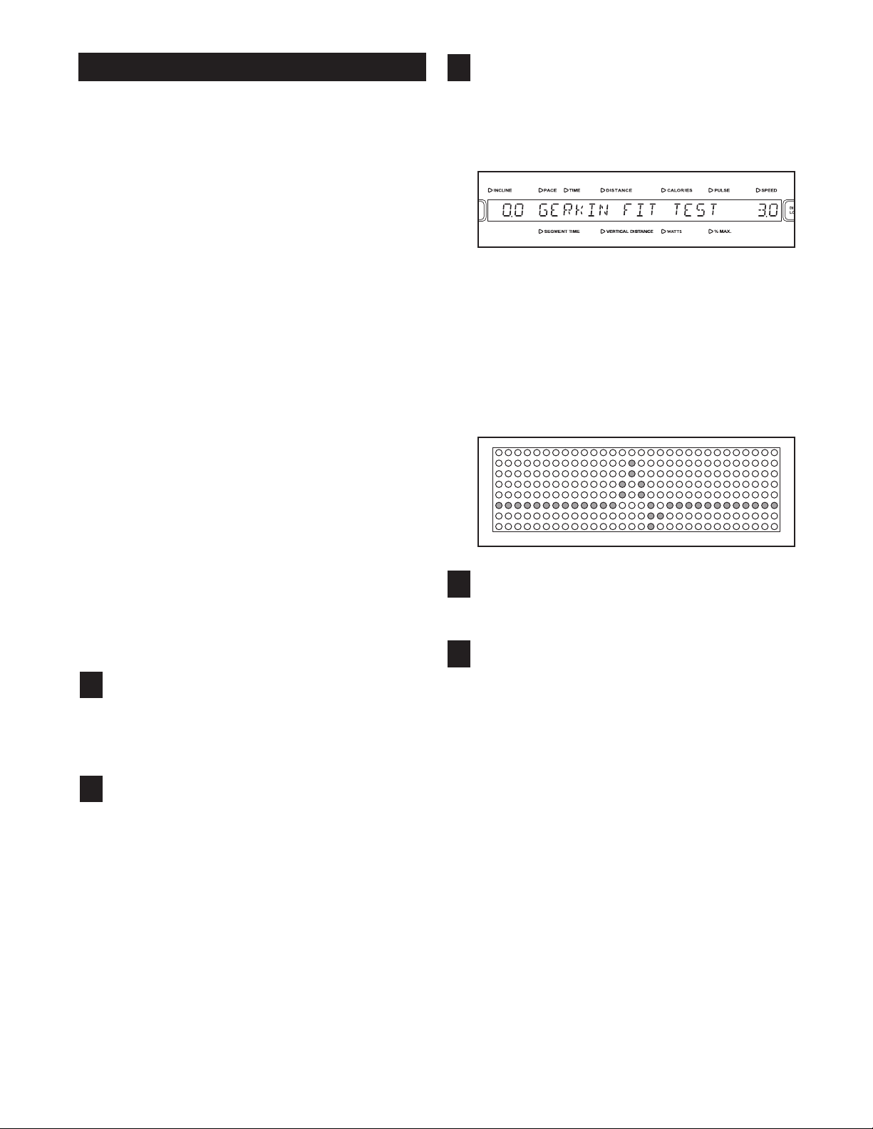
elect a FITNESS TEST program.
S
3
Press the FITNESS TEST button one, two, or
three times to select the GERKIN FIT TEST, the
BBELING FIT TEST, or the FREEMOTION FIT
E
TEST.
When a FITNESS TEST program is selected, the
name of the FITNESS TEST will appear in the
main display. The words ENTER AGE and the
current age setting will then be shown.
During a FITNESS TEST program, the matrix will
show a moving graphic that represents your heart
rate. Each time a heartbeat is detected, an additional peak will appear in the graphic.
The EBBELING FITNESS TEST is completed in 9 minutes.
The FREEMOTION FITNESS TEST is completed when
your heart rate reaches greater than 70% of your agepredicted maximum heart rate, or when the program
reaches 30 minutes.
Follow the steps below to use a FITNESS TEST program.
Put on a Polar®-compatible chest pulse sensor
1
(not included).
You must wear a chest pulse sensor to use a
FITNESS TEST program.
Insert the key into the console.
2
See GETTING STARTED on page 17.
Enter your age.
4
See step 3 on page 18.
Enter your weight.
5
See step 4 on page 19.
If you have selected the EBBELING FITNESS
TEST, continue to step 6. If you have selected
the GERKIN FITNESS TEST or the FREEMOTION FITNESS TEST, skip to step 7.
20

nter your gender.
E
6
If you selected the EBBELING FITNESS TEST,
you will be prompted to enter your gender. Either
he word MALE or the word FEMALE will appear
t
in the main display. To enter your gender, press
the + and – buttons beside the ENTER button.
When your gender is shown, press the ENTER
button.
When the EBBELING FITNESS TEST is completed, the walking belt will slow to a stop and
your VO2max will be shown in the main display.
When the FREEMOTION FITNESS TEST is completed, the walking belt will slow to a stop and
your VO2max and your fitness level will be shown
in the main display. Note: There are ten fitness
evels; fitness level 10 is the highest.
l
Press the QUICK START button to start the
7
program.
A moment after the button is pressed, the INCLINE TRAINER will automatically adjust to the
first speed and incline settings for the program.
Hold the handrails and begin walking.
Each FITNESS TEST is divided into several segments of different lengths. One speed setting and
one incline setting are programmed for each segment. The console will guide you through the FITNESS TEST and record your heart rate input to
determine your relative fitness level.
When the GERKIN FITNESS TEST is completed,
the walking belt will slow to a stop and your VO
max and your fitness level will be shown in the
main display. Note: There are 11.4 fitness levels;
fitness level 11.4 is the highest.
Note: The SPEED and INCLINE buttons will not
function while a FITNESS TEST program is selected. If your pulse is not detected during the program, the letters PLS will flash in the main display.
If this occurs, try the program again on another
day. Make sure that you are wearing a chest
pulse sensor as described in step 1 on page 20.
The FITNESS TEST programs cannot be stopped
temporarily and then restarted. However, the programs can be stopped at any time with the STOP
button. The main display will then show the words
FIT TEST ABORTED.
When the program is completed, remove the
8
key.
2
See step 10 on page 19.
21
OW TO USE A HEART RATE PROGRAM
H
HEART RATE programs automatically control the
peed and incline of the INCLINE TRAINER to keep
s
your heart rate near a target level while you exercise.
ollow the steps below to use a HEART RATE pro-
F
gram.
Put on a Polar
1
(not included).
You must wear a chest pulse sensor to use a
HEART RATE program.
Insert the key into the console.
®
-compatible chest pulse sensor
2
See GETTING STARTED on page 17.
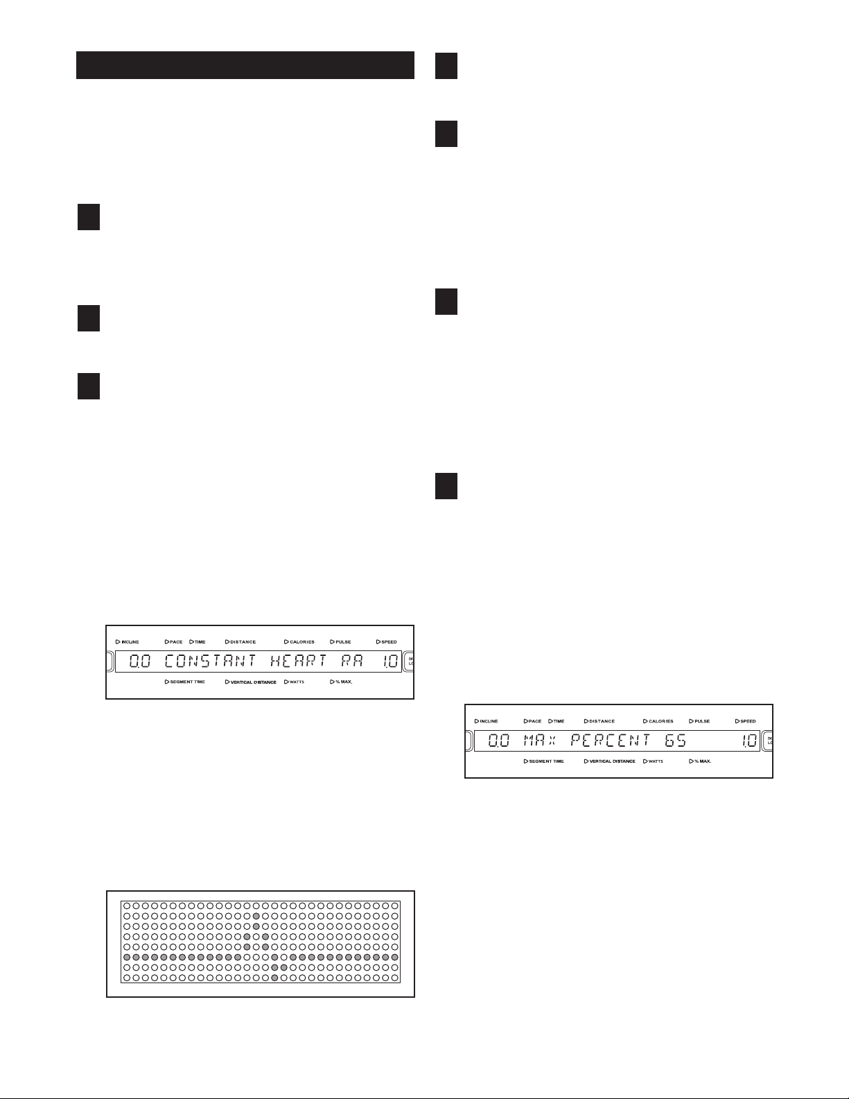
Select a HEART RATE program.
3
Press the HEART RATE button one, two, or three
times to select the CONSTANT HEART RATE,
VARIABLE HEART RATE, or FAT BURN program. Note: The CONSTANT HEART RATE program will keep your heart rate near a percentage
that you select. The VARIABLE HEART RATE
program will keep your heart rate within a target
range during your workout. The FAT BURN program will keep your heart rate near 65% of your
age-predicted maximum heart rate (see step 7 at
the right for an explanation of your age-predicted
maximum heart rate).
nter your age.
E
4
See step 3 on page 18.
Enter your weight.
5
See step 4 on page 19.
If you have selected the VARIABLE HEART
RATE program, continue to step 6. If you have
selected the CONSTANT HEART RATE program, skip to step 7. If you have selected the
FAT BURN program, skip to step 8.
Enter a minimum target heart rate setting.
6
The words MIN PERCENT and the minimum target heart rate setting for the program will be
shown in the main display. If desired, you can
change the minimum target heart rate setting by
pressing the + and – buttons beside the ENTER
button. The buttons can be held down to change
the minimum heart rate setting quickly. Then,
press the ENTER button.
Enter a target heart rate setting.
7
The words MAX PERCENT and the target heart
rate setting for the program will be shown in the
main display. The target heart rate setting represents a percentage of your age-predicted maxi-
mum heart rate. Your age-predicted maximum
heart rate is 220 minus your age. For example, if
you are 30 years old, your age-predicted maximum heart rate is 190 beats per minute (220 – 30
= 190). If you are 30 years old, a target heart rate
setting of 50 is equal to 95 beats per minute (50%
of 190 is 95).
When a HEART RATE program is selected, the
name of the program will appear in the main display. The words ENTER AGE and the current age
setting will then be shown.
During HEART RATE programs, the matrix will
show a moving graphic that represents your heart
rate. Each time a heartbeat is detected, an additional peak will appear in the graphic.
If desired, you can change the target heart rate
setting by pressing the + and – buttons beside the
ENTER button. The buttons can be held down to
change the target heart rate setting quickly. The
target heart rate setting can be from 45% to 85%
of your age-predicted maximum heart rate. Then,
press the ENTER button.
22

nter a program time.
E
8
The words ENTER TIME and a time setting of 15
minutes will appear in the main display. To
hange the length of time that the program will
c
last, press the + and – buttons beside the ENTER
button. Then, press the ENTER button.
Press the QUICK START button to start the
9
program.
A moment after the button is pressed, the INCLINE TRAINER will automatically adjust to the
first speed and incline settings for the program.
Hold the handrails and begin walking.
Each HEART RATE program is divided into 30-second segments. (The main display will show both
the time remaining in the program and the time remaining in the current segment of the program.)
One target heart rate setting is programmed for
each segment. (During the CONSTANT HEART
RATE program, the same target heart rate setting
will be programmed for all segments.)
the next segment. The speed and/or incline setting
will flash in the main display to alert you before the
speed and/or incline changes. The program will
ontinue until no time remains in the program. The
c
walking belt will then slow to a stop.
Note: The SPEED and INCLINE buttons will not
function while a HEART RATE program is selected. If your pulse is not detected during the program, the letters PLS will flash in the main display
and the speed and incline of the INCLINE
TRAINER may automatically decrease until your
pulse is detected. If this occurs, see the instructions included with your chest pulse sensor.
To stop the program at any time, press the STOP
button. HEART RATE programs should not be
stopped temporarily and then restarted. To use a
HEART RATE program again, reselect the program and start it at the beginning.
Follow your progress with the main display.
10
See THE MAIN DISPLAY on page 15.
When only four seconds remain in the first segment of the program, a series of tones will sound
and then the speed and/or incline of the INCLINE
TRAINER will change, if needed, to bring your
heart rate closer to the target heart rate setting for
When the program is completed, remove the
11
key.
See step 10 on page 19.
23

OW TO USE AN INTERVAL PROGRAM
H
The INTERVAL programs will automatically adjust the
incline of the walking belt as they guide you through an
effective interval training workout.
Insert the key into the console.
1
See GETTING STARTED on page 17.
Select an INTERVAL program.
2
Press the INTERVAL button one, two, or three
times to select the INTERVAL 1 TO 1, INTERVAL
1 TO 2, or INTERVAL 1 TO 3 program. When an
INTERVAL program is selected, the name of the
program will appear in the main display. The
words ENTER AGE and the current age setting
will then be shown.
the minimum incline you want to walk or run during your workout, press the + and – buttons beside the ENTER button; hold down the buttons to
nter the minimum incline quickly. Then press the
e
ENTER button.
Enter a maximum incline setting.
7
The words MAX INCLINE and the maximum incline setting will appear in the main display. To
enter the maximum incline you want to walk or run
during your workout, press the + and – buttons
beside the ENTER button; hold down the buttons
to enter the maximum incline quickly. Then press
the ENTER button.
Press the QUICK START button to start the
8
program.
When an INTERVAL program is selected, the matrix will show a graph representing the incline settings for the program.
Enter your age.
3
See step 3 on page 18.
Enter your weight.
4
See step 4 on page 19.
Enter a program time.
5
See step 8 on page 23.
Enter a minimum incline setting.
6
The words MIN INCLINE and the minimum incline
setting will appear in the main display. To enter
A moment after the button is pressed, the walking
belt will begin to move at 3 mph and the INCLINE
TRAINER will automatically adjust to the first incline setting for the program. Hold the handrails
and begin walking.
Each program is divided into several time segments
of different lengths. The main display will show
both the time remaining in the program and the
time remaining in the current segment of the program. One incline setting is programmed for each
segment. The incline setting for the first segment
is shown in the flashing left column of the matrix.
The incline settings for upcoming segments are
shown in the columns to the right.
After every 30 seconds that you exercise, a tone
will sound and the next column to the right will
begin to flash.
Note: If the length of the program exceeds the
number of columns in the matrix, the same column
will continue to flash, and all columns of indicators
will shift one position to the left once you have exercised for 7 1/2 minutes. The columns of indicators will continue to shift to the left after every 30
seconds, until you are finished exercising.
24

Note: You can manually override the incline setting for the current segment by pressing the INCLINE buttons. Every few times an INCLINE but-
on is pressed, an additional indicator will light or
t
darken in the flashing column. (If any of the
olumns to the right of the flashing column have
c
the same number of lit indicators as the flashing
column, an additional indicator may light or darken
in those columns as well.) Important: When the
next segment of the program begins, the INCLINE TRAINER will automatically adjust to the
incline setting for the next segment.
pressed, the speed will change by 0.1 mph. Note:
After the buttons are pressed, it may take a moment for the walking belt to reach the selected
peed setting.
s
Follow your progress with the main display.
10
See THE MAIN DISPLAY on page 15.
Measure your heart rate if desired.
11
See THE PULSE SENSOR on page 16.
To stop the program, press the STOP button. The
time will begin to flash in the main display. To
restart the program, press the QUICK START button.
Change the speed of the walking belt as
9
desired.
To change the speed of the walking belt, press the
SPEED + and – buttons. Each time a button is
When the program is completed, remove the
12
key.
See step 10 on page 19.
25

OW TO USE A WALK/RUN PROGRAM
H
The 5K program is designed to help you train for a 5K
race.
The 10K program is designed to help you train for a
10K race.
The CROSS COUNTRY program is designed to help
you train for a race of a length of your choice.
Insert the key into the console.
1
See GETTING STARTED on page 17.
Select a WALK/RUN program.
2
Press the WALK/RUN button one, two, or three
times to select the 5K, 10K, or CROSS COUNTRY
program. When a WALK/RUN program is selected, the name of the program will appear in the
main display. The words ENTER AGE and the
current age setting will then be shown.
If you have selected the 5K or 10K program,
skip to step 6. If you have selected the CROSS
COUNTRY program, continue to step 5.
Enter a distance goal.
5
If you have selected the CROSS COUNTRY pro-
ram, the words ENTER DISTANCE and a dis-
g
tance setting of 10 miles will appear in the main
display. To change the distance you want to walk
or run during your workout, press the + and – buttons beside the ENTER button. Then, press the
ENTER button.
Enter a program time.
6
See step 8 on page 23. Note: The speed of your
workout depends on the program time that you
enter.
Press the QUICK START button to start the
7
program.
A moment after the button is pressed, the walking
belt will begin to move at the calculated start
speed. Hold the handrails and begin walking.
When a WALK/RUN program is selected, the matrix will show a graph representing the speed settings for the program.
Enter your age.
3
See step 3 on page 18.
Enter your weight.
4
See step 4 on page 19.
If the speed of the walking belt is too fast or too
slow, you can change it by pressing the SPEED +
and – buttons. Note: This will change the length of
time of your program.
Change the incline of the INCLINE TRAINER as
8
desired.
See step 7 on page 19.
Follow your progress with the main display.
9
See THE MAIN DISPLAY on page 15.
Measure your heart rate if desired.
10
See THE PULSE SENSOR on page 16.
When the program is completed, remove the
11
key.
See step 10 on page 19.
26

OW TO USE A TERRAIN PROGRAM
H
During the HILL program, the incline of the INCLINE
RAINER will depend on the vertical distance goal and
T
the speed setting that you set. The incline will remain
constant with only minor adjustments throughout the
program to help you reach your vertical distance goal.
During the PEAKS program, the incline will increase
and decrease. The number of times that the incline will
increase and decrease will depend on the maximum
incline setting and the program length that you select.
During the ALL-TERRAIN program, the incline will
sharply increase and then sharply decrease repeatedly. The number of times that the incline will increase
and decrease will depend on the maximum incline setting and the program length that you select.
Insert the key into the console.
1
See GETTING STARTED on page 17.
Enter a maximum incline setting.
6
The words MAX INCLINE and the incline setting
will appear in the main display. To enter a different maximum incline setting for your workout,
ress the + and – buttons beside the ENTER but-
p
ton; hold down the buttons to enter the maximum
ncline quickly. Then, press the ENTER button
i
and skip to step 9.
Enter a vertical distance goal.
7
The words VERTICAL DISTANCE and the vertical
distance goal will appear in the main display. To
enter a different vertical distance goal, press the +
and – buttons beside the ENTER button; hold
down the buttons to enter the goal quickly. Then,
press the ENTER button.
Select a TERRAIN program.
2
Press the TERRAIN button one, two, or three
times to select the HILL, PEAKS, or ALL-TERRAIN
program. When a TERRAIN program is selected,
the name of the program will appear in the main
display. The words ENTER AGE and the current
age setting will then be shown. When a TERRAIN
program is selected, the matrix will show a graph
representing the incline settings for the program.
Enter your age.
3
See step 3 on page 18.
Enter your weight.
4
See step 4 on page 19
Enter a program time.
5
See step 8 on page 23.
If you have selected the PEAKS or ALL-TERRAIN program, continue to step 6. If you have
selected the HILL program, skip to step 7.
Enter a speed setting.
8
The words ENTER SPEED and the speed setting
will appear in the main display. To enter a different
speed setting, press the + and – buttons beside
the ENTER button; hold down the buttons to enter
the speed quickly. Then, press the ENTER button.
Press the QUICK START button to start the
9
program.
A moment after the button is pressed, the walking
belt will begin to move at 3 mph for the PEAKS or
ALL-TERRAIN program, or at the speed setting
you entered for the HILL program. Hold the
handrails and begin walking.
If the speed of the walking belt is too fast or too
slow, you can change it by pressing the SPEED +
and – buttons.
Follow your progress with the main display.
10
See THE MAIN DISPLAY on page 15.
Measure your heart rate if desired.
11
See THE PULSE SENSOR on page 16.
When the program is completed, remove the
12
key.
See step 10 on page 19.
27

OW TO USE A FITNESS OR RANDOM PROGRAM
H
The FITNESS program controls the speed and incline
of the INCLINE TRAINER to create a workout with a
warm-up period, a steady workout, and a cool-down
period.
If you have selected a RANDOM program, continue to step 5. If you have selected a FITNESS
program, skip to step 7.
Enter a maximum incline setting.
5
See step 7 on page 24.
The RANDOM program creates a different incline program every time it is selected for a variety of workouts.
Insert the key into the console.
1
See GETTING STARTED on page 17.
Select the FITNESS program or the RANDOM
2
program.
Press the MIX button once or twice to select the
FITNESS program or the RANDOM program.
When a FITNESS or RANDOM program is selected, the name of the program will appear in the
main display. The words ENTER AGE and the
current age setting will then be shown.
When a FITNESS program is selected, the matrix
will show a graph representing the speed settings
for the program.
When a RANDOM program is selected, the matrix
will show a graph representing the incline settings
for the program.
Enter a program time.
6
See step 8 on page 23.
Press the QUICK START button to start the
7
program.
A moment after the button is pressed, the walking
belt will begin to move at 5 mph for the FITNESS
program, or at 3 mph for the RANDOM program.
Hold the handrails and begin walking.
The speed of the walking belt will fluctuate between 5 and 8 mph throughout the FITNESS program; the speed of the walking belt will be 3 mph
for the entire RANDOM program.
If the speed of the walking belt is too fast or too
slow, you can change it by pressing the SPEED +
and – buttons.
Change the incline of the INCLINE TRAINER as
8
desired.
See step 7 on page 19.
Follow your progress with the main display.
9
See THE MAIN DISPLAY on page 15.
Enter your age.
3
See step 3 on page 18.
Enter your weight.
4
See step 4 on page 19.
28
Measure your heart rate if desired.
10
See THE PULSE SENSOR on page 16.
When the program is completed, remove the
11
key.
See step 10 on page 19.

OW TO USE A CUSTOM PROGRAM
H
Insert the key into the console.
1
ee GETTING STARTED on page 17.
S
Select the CUSTOM programs.
2
To select the CUSTOM programs, press the MIX
button repeatedly until the word CUSTOM appears in the main display.
Select one of the three CUSTOM program.
3
The name of the currently selected CUSTOM program will appear in the main display. There are
three CUSTOM programs. To select a different
CUSTOM program, press the + and – buttons beside the ENTER button. When you see the CUSTOM program you want, press the ENTER button.
Each custom program is divided into several segments. One speed setting and one incline setting
is programmed for each segment. (The same
peed and/or incline setting may be programmed
s
for two or more consecutive segments.) The in-
line setting for the first segment is shown in the
c
flashing column of the matrix. The incline settings
for the next several segments are shown in the
columns to the right.
After every 30 seconds that you exercise, a tone
will sound and the next column to the right will
begin to flash.
Note: If the length of the program exceeds the
number of columns in the matrix, the same column
will continue to flash, and all columns of indicators
will shift one position to the left once you have exercised for 7 1/2 minutes. The columns of indicators will continue to shift to the left after every 30
seconds, until you are finished exercising.
To stop the program temporarily, press the STOP
button. The time will begin to flash. To restart the
program, press the QUICK START button.
Note: The matrix will show the incline settings
of the program. If only three rows of indicators
appear in the matrix, see HOW TO USE THE
MAINTENANCE MODE on page 30, and follow
the instructions to step 6.
Enter your age.
4
See step 3 on page 18.
Enter your weight.
5
See step 4 on page 19.
Press the QUICK START button to start the
6
program.
A moment after the button is pressed, the INCLINE TRAINER will automatically adjust to the
first speed and incline settings of the program.
Hold the handrails and begin walking.
Follow your progress with the main display.
7
See THE MAIN DISPLAY on page 15.
Measure your heart rate if desired.
8
See THE PULSE SENSOR on page 16.
When the program is completed, remove the
9
key.
See step 10 on page 19.
29
OW TO USE THE MAINTENANCE MODE
H
ress the ENTER button again and set the
P
5
delay time for the timeout mode.
The console features a maintenance mode that allows
you to access information and to view and change various default settings. Follow the steps below to use the
maintenance mode.
nsert the key into the console.
I
1
See GETTING STARTED on page 17.
Hold down the ENTER button and the CLEAR
2
button simultaneously for two seconds to select the maintenance mode.
When the maintenance mode is selected, the
words MAINTENANCE MODE will appear in the
main display. The word HOURS and the total
number of hours that the INCLINE TRAINER has
been used will then be shown.
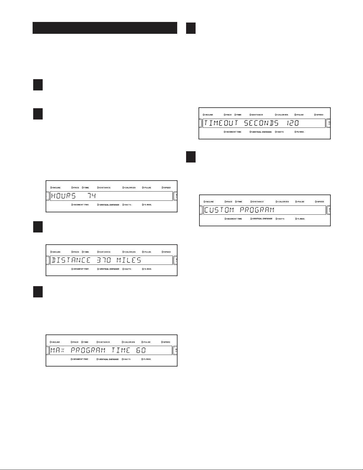
Any time that the INCLINE TRAINER is not used
or several minutes, the console will enter a time-
f
out mode and the words SELECT PROGRAM TO
BEGIN will appear in the main display. To set the
number of seconds before the console will enter
the timeout mode, press the + and – buttons
above the ENTER button. The delay time can be
from 15 to 120 seconds.
Press the ENTER button again to create the
6
CUSTOM programs.
The words CUSTOM PROGRAM will appear in
the main display.
Press the ENTER button to view the total dis-
3
tance that the walking belt has moved.
Press the ENTER button again and set a maxi-
4
mum program time.
To set a maximum program time, press the + and
– buttons beside the ENTER button. The maximum program time can be up to 90 minutes.
You can design up to three CUSTOM programs.
To select a CUSTOM program, press the + and –
buttons beside the ENTER button. When you see
the CUSTOM program you want to design (PROGRAM 1, PROGRAM 2, or PROGRAM 3), press
the ENTER button.
Note: If the CUSTOM program has not yet
been defined, only three rows of indicators will
appear in the matrix.
30
Enter a name for the program. The name can
have up to twelve characters, including spaces.
To enter a name, press the + and – buttons be-
ide the ENTER button until the desired character
s
appears in the display. Then, press the ENTER
utton. If you select the wrong character, press
b
the CLEAR button. Continue entering a name in
this way. Then, press the ENTER button.
Next, enter a program time by pressing the + and
– buttons beside the ENTER button. Then, press
the ENTER button.
See the matrix. Each CUSTOM program is divided into 30-second segments. One speed setting and one incline setting can be programmed
for each segment. The incline setting for the first
segment is shown in the flashing column of the
matrix.
Enter a maximum incline setting for the first segment of the program by pressing the QUICKTOUCH INCLINE buttons and the + and – buttons
beside the ENTER button. Next, enter a speed
setting for the first segment of the program by
pressing the SPEED + and – buttons. Then, press
the ENTER button. Note: The maximum incline
setting will appear in the first column of the matrix.
The speed settings of the program will not appear
in the matrix.
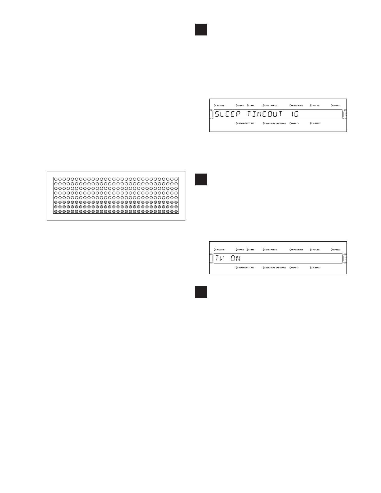
ress the ENTER button again and set the
P
7
delay time for the sleep timeout mode.
Any time that the INCLINE TRAINER is not used
or several minutes, the console will enter a sleep
f
timeout mode. To set the number of minutes before the console will enter the sleep timeout mode,
press the + and – buttons above the ENTER button. The delay time can be from 1 to 10 minutes.
If you have the Basic console, skip to step 9. If
you have the Workout TV console, continue to
step 8.
Press the ENTER button again and enable or
8
disable the TV.
To make the TV available for use, press the + or –
button above the ENTER button until the words TV
ON appear in the main display. To prevent the TV
from being used, press the + or – button until the
words TV OFF appear.
Hold down the ENTER button and the CLEAR
9
button simultaneously for two seconds to exit
the maintenance mode.
Program a speed setting and an incline setting for
the second segment as described above.
Continue programming speed and incline settings
for the remaining segments. After you have entered the last incline setting, the words CUSTOM
PROGRAM CREATED will appear in the main
display. The speed and incline settings that you
have programmed and the number of segments
that you have programmed will then be saved in
memory and you will be returned to the maintenance mode.
To exit the maintenance mode at any time, hold
down the ENTER button and the CLEAR button
simultaneously for two seconds.
31
OW TO DISABLE THE SAFETY KEY
H
If your INCLINE TRAINER is connected to a 120-volt
circuit, you can disable the safety key so the INCLINE
TRAINER does not require the use of a key. If your
INCLINE TRAINER is connected to a 220-volt cir-
uit, you cannot disable the safety key.
c
Remove the key from the console.
1
Make sure the key is not inserted into the console;
the main display will appear blank.
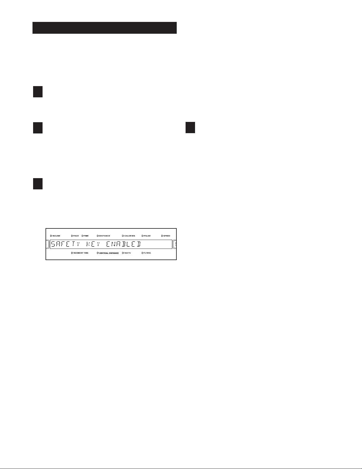
To allow the INCLINE TRAINER to be used without the safety key, press the + or – button until the
words SAFETY KEY DISABLED appear. Note:
he next time the key is inserted into the console,
T
the safety key will automatically be enabled and
he console will require the use of the safety key
t
again.
To require the use of the safety key with the console, press the + or – button above the ENTER
button until the words SAFETY KEY ENABLED
appear in the main display, or insert the key into
the console.
Hold down the ENTER button and the CLEAR
2
button simultaneously for two seconds to select the maintenance mode.
When the maintenance mode is selected, the
words MAINTENANCE MODE will appear in the
main display.
Press the ENTER button repeatedly to enable
3
or disable the safety key.
Press the Enter button repeatedly until the words
SAFETY KEY ENABLED appear in the main display.
Hold down the ENTER button and the CLEAR
4
button simultaneously for two seconds to exit
the maintenance mode.
To exit the maintenance mode, hold down the
ENTER button and the CLEAR button simultaneously for two seconds.
32
PREVENTIVE MAINTENANCE
Regular maintenance is necessary for optimal performance and long life of the INCLINE TRAINER. Please
ead and follow all instructions below. If the INCLINE TRAINER is not maintained as described, compo-
r
nents may wear excessively, the INCLINE TRAINER may be damaged, and the warranty will be voided. If
you have questions about maintenance, see HOW TO CONTACT CUSTOMER CARE on page 2 of this manual.
CAUTION: Make sure to remove the key and unplug the power cord before performing any maintenance
rocedures.
p
WEEKLY MAINTENANCE
1. Unplug the power cord. Inspect and properly tighten all external parts of the INCLINE TRAINER.
2. Apply a mild multi-purpose cleaner to a 100% cotton cloth and remove any dust and grime from the handrails,
uprights, foot rails, frame, and motor hood. In addition, wipe the walking platform along the sides of the walking belt. Do not wipe under the walking belt. Apply a small amount of mild multi-purpose cleaner to a 100%
cotton cloth and wipe the console and the screens. Do not spray cleaner directly onto the INCLINE
TRAINER or use ammonia or acid-based cleaners.
3. Make sure that the walking belt is centered and properly tightened. If it is centered and runs smoothly, do not
make any adjustments. If the walking belt needs to be adjusted, see pages 37 and 38.
MONTHLY MAINTENANCE
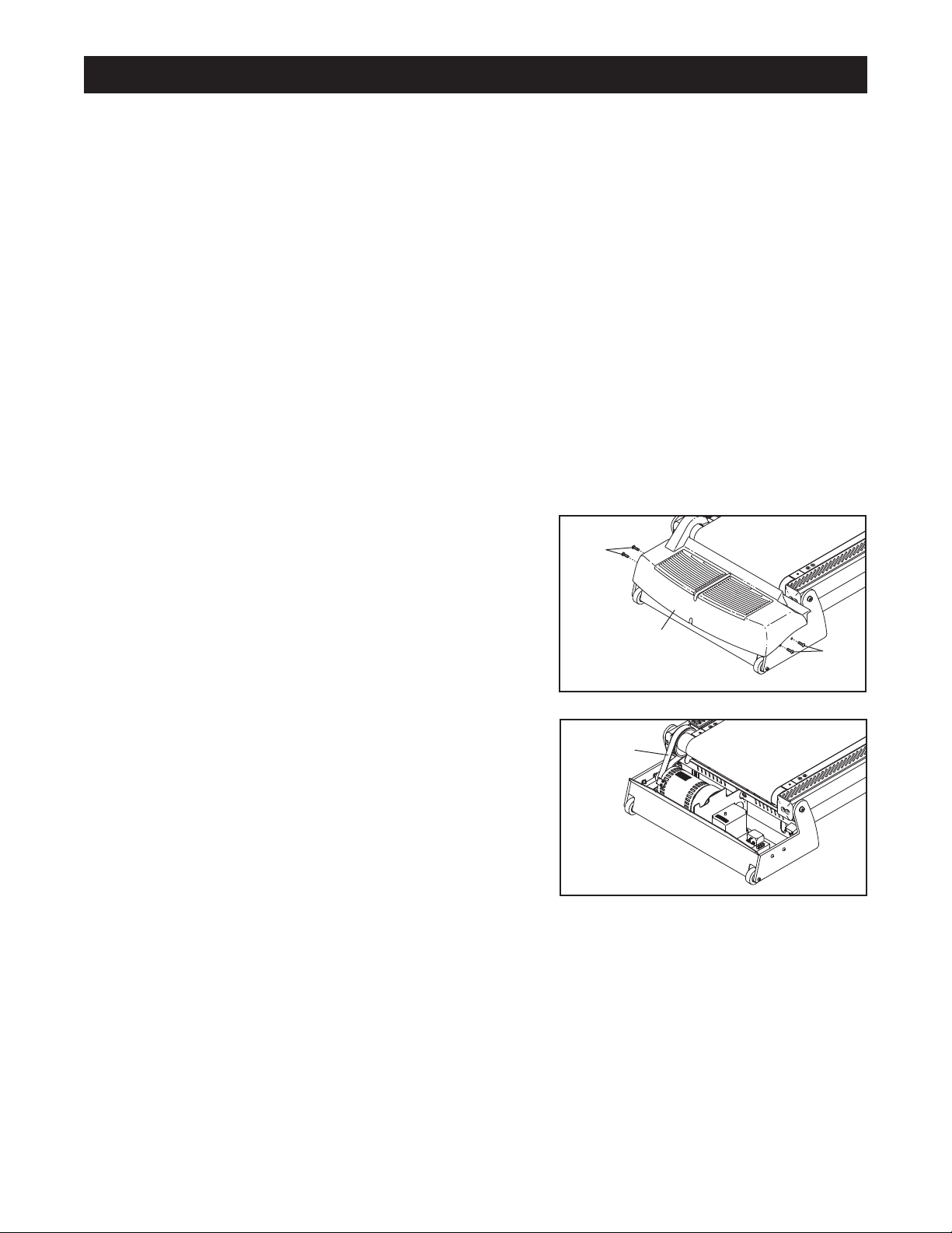
1. Unplug the power cord. Remove the Hood Support Bolts
(37) attaching the Motor Hood (91), and lift off the Motor
Hood.
2. Using a hand-held vacuum, clean the area under the Motor
Hood (not shown). Be careful to avoid touching any com-
ponents. Check the Motor Belt (82) for wear and cracks. If the
motor belt needs to be replaced, see HOW TO CONTACT
CUSTOMER CARE on page 2.
3. Plug in the power cord and insert the key into the console. Press the START button. Be careful to avoid in-
jury; keep your hands away from moving parts and make sure that your clothes cannot become
caught in moving parts. While the walking belt is moving, check the INCLINE TRAINER for unusual noises
or odors. If any of these problems exists, see HOW TO CONTACT CUSTOMER CARE on page 2. Remove
the key and unplug the power cord. Reattach the Motor Hood (91) with the Hood Support Bolts (37).
1
37
91
37
2
82
33
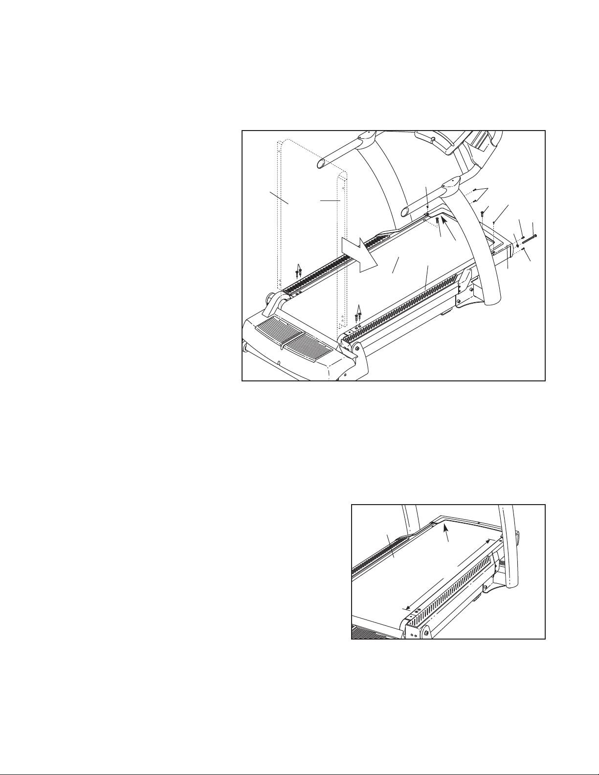
TURNING THE WALKING PLATFORM
50”
Both sides of the walking platform are designed to be used as walking surfaces. Inspect the walking platform peri-
dically for wear. If there is any wood showing through the phenolic coating, or if the surface is damaged, the
o
walking platform should be turned over. The walking platform will need to be turned over and the walking belt re-
laced (see page 35) after every 16,000 to 24,000 kilometers (10,000 to 15,000 miles). Follow the instructions
p
below to turn over the walking platform.
1. Remove the key and unplug the
power cord. Remove the Front
Cover Screws (16), Cover Screws
(2) and the Front Cover (17).
Remove the Front Roller
Adjustment Bolt (19) and the Front
Roller Washer (14) from each side
of the Front Roller (13 ).
2. Remove the four Rear Walking
Platform Bolts (10) and the two
Front Walking Platform Bolts (20).
(Note: Be very careful to avoid
chipping or damaging the phenolic coating on the Walking
Platform [23].) Lift the Front
Roller (13) and slide it out of the
Walking Belt (18). Lift the Walking
Platform and the Walking Belt to
the position shown by the dotted
lines. Slide the Walking Platform
out of the Walking Belt, turn it, and
then slide it back into the Walking
Belt.
1–4
18
10
23
10
18
2
23
20
13
20
16
14
17
2
16
19
16
3. Lay down the Walking Platform (23) and the Walking Belt (18). Slide the Front Roller (13) back into the
Walking Belt.
4. Reattach the Walking Platform Bolts (10, 20). Thread the Front Roller Adjustment Bolts (19) with the Washers
(14) into the Roller (13). Reattach the Front Cover (17) with the Front Cover Screws (16) and Cover Screws
(2).
5. Next, the Walking Belt (18) will need to be adjusted to the
proper tension. Using chalk, make two marks on the Walking
Belt exactly 1.25 m (50 in.) apart, as shown in the drawing.
Tighten both Front Roller Adjustment Bolts (19, see the drawing above) until the two chalk marks move apart an additional
5 to 6 mm (3/16 to 1/4 in.). As you tighten the Roller
Adjustment Bolts, the Front Roller (13) will move. If the Front
Roller stops moving, do not further tighten the Roller
Adjustment Bolts; see HOW TO CONTACT CUSTOMER
CARE on page 2. Make sure to keep the Walking Belt cen-
tered.
5
18
13
34

REPLACING THE WALKING BELT
When the walking belt becomes worn, it should be replaced. The walking belt will need to be replaced after every
6,000 to 24,000 kilometers (10,000 to 15,000 miles). See the Service Manual for replacement instructions. See
1
HOW TO CONTACT CUSTOMER CARE on page 2 to order a new walking belt.
REPLACING THE WALKING PLATFORM
When both sides of the walking platform become worn, the walking platform should be replaced. The walking
platform will need to be replaced after every 32,000 to 48,000 kilometers (20,000 to 30,000 miles). See HOW TO
CONTACT CUSTOMER CARE on page 2 to order a new walking platform. Follow the instructions on page 34 to
replace the walking platform.
35
SIX-MONTH PREVENTIVE MAINTENANCE RECORD
Photocopy this form and use it to record the preventive maintenance performed on the INCLINE TRAINER. Each
copy of the form can be used for six months (26 weeks). When maintenance is performed, write the date in the ap-
ropriate spaces. Make sure to perform each maintenance procedure as described on pages 33 to 35. If the
p
procedures are not performed as described, components may wear excessively, the INCLINE TRAINER
may be damaged, and the warranty will be voided.
Week1
Week2
Week3
Week4
Week5
Week6
Week7
Week8
Week9
Week10
Week11
Week12
Weekly Maintenance
Inspect and
tighten all external parts of
the INCLINE
TRAINER.
/ /
/ /
/ / / /
/ / / /
/ / / /
/ / / /
/ / / /
/ / / /
/ / / /
/ / / /
/ / / /
/ / / /
Clean the
INCLINE
TRAINER.
/ /
/ /
Check the
walking belt for
proper tension
and alignment.
/ /
/ /
/ /
/ /
/ /
/ /
/ /
/ /
/ /
/ /
/ /
/ /
Monthly Maintenance
Remove the
motor hood and
vacuum the
motor compartment.
Check the
motor belt for
cracks and
other wear.
/ / / / / /
/ / / / / /
Check the
motor for arcing; check for
noises or
odors.
Week13
Week14
Week15
Week16
Week17
Week18
Week19
Week20
Week21
Week22
Week23
Week24
Week25
Week26
Walking Platform Turned/Replaced Walking Belt Replaced
/ / / /
/ / / /
/ / / /
/ / / /
/ / / /
/ / / /
/ / / /
/ / / /
/ / / /
/ / / /
/ / / /
/ / / /
/ / / /
/ / / /
/ /
/ /
/ /
/ /
/ /
/ /
/ /
/ /
/ /
/ /
/ /
/ /
/ /
/ /
/ /
/ / / / / /
/ / / /
/ / / / / /
/ / / / / /
/ / / /
/ /
36

TROUBLESHOOTING
ost INCLINE TRAINER problems can be solved by following the steps below. Find the symptom that ap-
M
plies, and follow the steps listed. If further assistance is needed, see HOW TO CONTACT CUSTOMER
CARE on page 2 of this manual.
. SYMPTOM: THE POWER DOES NOT TURN ON
1
a. Make sure that the power cord is plugged into a properly grounded outlet. (See page 12.)
b. Make sure that the key is inserted into the console.
c. Check the on/off circuit breaker located on the INCLINE TRAINER near the
power cord. Make sure that the on/off circuit breaker is switched to the “on”
position.
2. SYMPTOM: THE POWER TURNS OFF DURING USE
a. Check the on/off circuit breaker located on the INCLINE TRAINER near the power cord. (See drawing 1. c.
above.) Make sure that the on/off circuit breaker is switched to the “on” position.
b. Make sure that the power cord is plugged in.
c. Remove the key from the console. Reinsert the key into the console.
d. Check the walking belt and the walking platform for excessive wear. Replace the walking belt or the walking
platform if necessary.
e. If the power still turns off during use, see HOW TO CONTACT CUSTOMER CARE on page 2.
3. SYMPTOM: THE WALKING BELT SLOWS WHEN WALKED ON
a. If the walking belt is overtightened, performance may
decrease and the walking belt may be damaged. If
the walking belt is properly tightened, you should be
able to lift each side of the walking belt 2.5 to 5 cm (1
to 2 in.) off the walking platform. If adjustments need
to be made, first remove the key and unplug the
power cord. Using a 7/32" hex key, turn both roller
adjustment bolts counterclockwise 1/4 of a turn.
Then, plug in the power cord, insert the key, and use
the INCLINE TRAINER for a few minutes. Be careful
to keep the walking belt centered. Repeat until the
walking belt is properly tightened. Note: To tighten the
walking belt, see step 4. c. on page 38.
a
c
“On”
Position
2.5 to 5 cm
Roller Adjustment Bolts
b. If the walking belt still slows when walked on, see HOW TO CONTACT CUSTOMER CARE on page 2.
37
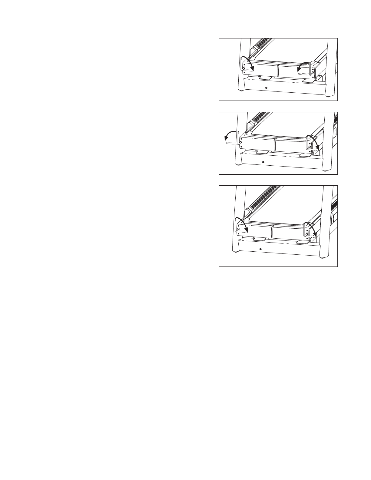
4. SYMPTOM: THE WALKING BELT IS OFF-CENTER OR SLIPS WHEN WALKED ON
a. If the walking belt has shifted to the right: Remove the
ey and unplug the power cord. Using a 7/32” hex key,
k
turn the roller adjustment bolts in the directions shown, 1/4
f a turn each. Be careful not to overtighten the walking
o
belt. Then, plug in the power cord, insert the key, and use
the INCLINE TRAINER for a few minutes. Repeat until the
walking belt is centered.
b. If the walking belt has shifted to the left: Remove the
key and unplug the power cord. Using a 7/32” hex key,
turn the roller adjustment bolts in the directions shown, 1/4
of a turn each. Be careful not to overtighten the walking
belt. Then, plug in the power cord, insert the key, and use
the INCLINE TRAINER for a few minutes. Repeat until the
walking belt is centered.
c. If the walking belt slips when walked on: Remove the
key and unplug the power cord. Using a 7/32” hex key,
turn both roller adjustment bolts clockwise 1/4 of a turn.
When the walking belt is properly tightened, you should be
able to lift each side of the walking belt 2.5 to 5 cm (1 to 2
in.) off the walking platform. The center of the walking belt
should just touch the walking platform. Make sure to keep
the walking belt centered. Then, plug in the power cord, insert the key, and run the INCLINE TRAINER for a few minutes. Repeat until the walking belt is properly tightened.
Note: As you tighten the roller adjustment bolts, the front
roller will move. If the front roller stops moving, do not
further tighten the roller adjustment bolts; see HOW
TO CONTACT CUSTOMER CARE on page 2.
a
Right
b
Left
c
5. SYMPTOM: THE WALKING BELT STOPS OR THE INCLINE CANNOT BE ADJUSTED EVEN THOUGH
THE CONSOLE REMAINS LIT
a. This indicates that a controller error may have occurred. To correct the problem, turn the power switch off,
wait 5 seconds and then turn the power switch back on.
6. SYMPTOM: THE INCLINE SYSTEM DOES NOT FUNCTION PROPERLY OR THE INCLINE SYSTEM DOES
NOT APPEAR TO BE AT THE INCLINE LEVEL SHOWN IN THE MAIN DISPLAY
a. The incline system may need to be calibrated. To initiate the calibration routine, turn the power switch off,
wait 5 seconds and then turn the power switch back on. During the calibration routine, the INCLINE TRAINER
will automatically travel to the lowest incline level and then return to level.
b. If the incline system still does not function properly, see HOW TO CONTACT CUSTOMER CARE on page 2.
38

200
180
160
140
120
100
80
25 30 35 40 45 50 55 60 65 70
Pulse
Age
Health Fitness Advanced
EXERCISE GUIDELINES
FACTORS IN A SENSIBLE DIET
Choose high-fiber, low-fat, and low-sugar
•
foods: fruits, vegetables, and whole grains.
• Eat at least five servings of fruits and
vegetables daily.
• Reduce red meat consumption; eat lean meat,
white meat, and fish.
• Choose healthful snacks; bring healthful foods
with you to work or in the car.
• Eat regular meals or mini-meals. Control your
portion size—don't binge or overeat. Eat
slowly.
• Reduce fast food and pre-packaged meals.
• Pay attention to fat content and calories.
• Limit alcoholic beverages and caffeine.
• Drink at least eight to ten glasses of water
daily.
Determine your target heart rate.
3
Your target heart rate (THR), is the rate at which
you would like your heart to work during aerobic
xercise. It is expressed as a percentage of your
e
maximum heart rate (MHR). MHR is the maximum
number of times that your heart can pump during
one minute. To determine your approximate MHR,
subtract your age (in years) from 220. This is only
an estimation of your MHR—only clinical stress
testing can provide an actual MHR reading.
Once you have determined your MHR, you can
establish your target heart rate zone. Beginning
exercisers may wish to start at 60 to 70 percent of
their MHR. This level is called the Health level.
Exercise at 70 to 85 percent of your MHR for the
optimal training, aerobic, or cardiovascular level—
the Fitness level. Advanced exercisers, or those
wishing to do sports, athletic conditioning, or interval training workouts should exercise at 80 to 85
percent of the MHR for short periods of time. The
chart below shows Target Heart Rate Zones for
Health, Fitness, and Advanced exercisers.
EXERCISE STEPS
The following nine steps for designing your exercise
program were developed by exercise physiologists at
FreeMotion Fitness. The actual exercise you perform
is only a part of a safe and effective training program.
There are many other aspects to developing a life-long
commitment to physical fitness.
Consult your physician before beginning
1
any exercise program.
A medical examination or consultation with your
physician is essential.
Establish personal fitness goals.
2
Set attainable, realistic goals. Reward yourself
when you meet your goals. Remember, your
goals should act as a guide for your workout
program.
Be sure to check your heart rate at least twice
during an aerobic conditioning session. First,
check your heart rate five minutes into your workout to be sure that you are at the proper intensity.
Then, check it again near the end of your workout
to verify that you have maintained your target
heart rate for the recommended period of time.
TARGET HEART RATE ZONES
Beginner,
low-intensity +
long duration =
fat burning
Optimal training, aerobic or
cardiovascular
Sports, athletic
conditioning,
interval training
39

EIGHT LOSS TIPS
W
At least four, 30-minute workouts per week,
along with a reduced-calorie diet, are
ecommended if you are trying to lose weight.
r
However, be sure to stay within your target heart
rate zone and exercise a maximum of 5 days per
week for 60 minutes per workout.
Good posture is the key to safe, comfortable
workouts. Keep your chin up and your head
facing forward. Align your head and shoulders
with your hips. Avoid leaning forward. Keep your
back straight.
Warm up before you begin.
4
A warm-up routine prepares your body and mind
for vigorous exercise. It also helps provide insurance against injury and soreness. Warm up with
two to five minutes of slow exercise, at minimal intensity.
3. Hamstring Stretch—Sit with one leg extended.
Bring the sole of the opposite foot toward you and
rest it against the inner thigh of your extended leg.
each toward your toes as far as possible. Hold
R
for 15 to 30 seconds, then relax. Repeat 3 times
or both legs. Stretches: Hamstrings, lower back,
f
and groin.
4. Inner Thigh Stretch—Sit with the soles of your
feet together and your knees outward. Pull your
feet toward your groin area as far as possible.
Hold for 15 to 30 seconds, then relax. Repeat 3
times. Stretches: Quadriceps and hip muscles.
5. Quadriceps Stretch—With one hand against a
wall for balance, reach back and grasp one foot
with your other hand. Bring your heel as close to
your buttocks as possible. Hold for 15 to 30
seconds, then relax. Repeat 3 times for each leg.
Stretches: Quadriceps and hip muscles.
1
Stretch after your warm-up.
5
A pliable, well-stretched muscle is less susceptible to injury. Perform the recommended stretches
on a smooth, flat surface.
The correct form for several stretches is described
below (see the drawings at the right). Be sure to
move slowly as you stretch—never bounce.
1. Toe Touch Stretch—Sit with your knees bent
slightly and slowly bend forward from your hips.
Allow your back and shoulders to relax as you
reach toward your toes as far as possible. Hold for
15 to 30 seconds, then relax. Repeat 3 times.
Stretches: Hamstrings, back of knees, and back.
2. Calf/Achilles Stretch—With one leg in front of
the other, reach forward and place your hands
against a wall. Keep your back leg straight and
your back foot flat on the floor. Bend your front
leg, lean forward, and move your hips toward the
wall. Hold for 15 to 30 seconds, then relax.
Repeat 3 times for each leg. To cause further
stretching of the achilles tendons, bend your back
leg as well. Stretches: Calves, achilles tendons,
and ankles.
2
4
3
5
40

BENEFITS OF AEROBIC EXERCISE
• Effective weight loss and management
• Added protection from heart disease
Increased strength and health of bones
•
Higher levels of energy for greater productivity
•
during the day
• Healthy stress relief from a pressure-packed
day
• Greater intellectual capacity and productivity
Get FIT with FreeMotion Fitness.
6
Effective aerobic exercise has three major parts:
frequency, intensity, and time. The acronym "FIT"
may help you to remember these three parts:
“F” stands for the frequency of your work-
F
outs. Three to five workouts per week are
recommended. Exercise at least four times a
week for weight loss.
“I” refers to the intensity of your workout.
I
Check your heart rate at least twice during
your aerobic exercise session: once during the
session and once again at the end. Maintain a
workout intensity level within your Target Heart
Rate Zone. You can measure your heart rate
using the handgrip pulse sensor or the method
described below:
1. Lower your wrist below your heart level. This
will make your heart rate stronger and easier to
feel.
2. Using the tips
of the index and
middle fingers of
your right hand,
touch your left
wrist, one-fourth
inch from your
wrist joint, at the
base of your
thumb.
3. Apply minimal pressure with both fingers—let
the beat come to your fingers. If you can't find
your pulse, use the opposite wrist and hand.
“T” is for the time or duration of your workout.
T
Beginning exercisers may wish to start with 5
to 10 minutes of aerobic activity. Those in aver-
ge physical condition should exercise for 20 to
a
30 minutes. Highly fit people, or people who want
o lose weight, should exercise for 30 to 60 min-
t
utes. The key is to maintain your target heart rate
for the duration of the workout period.
Remember to take it slowly. Fitness is a lifelong
commitment. If you can't go the full 20 minutes
from the start, which is common, try to exercise
for five minutes at a time, a couple of times a day.
Recent research indicates that several short
workouts in one day can also provide fitness
benefits. Gradually, your stamina will increase
and it will become easier to exercise for longer
periods of time.
Cool down after aerobic exercise.
7
Keep moving! It is important that you cool down
properly to allow your heart rate to decrease
slowly after it has been elevated. This helps the
blood flow from your extremities back to your
heart. Keep your legs moving on the INCLINE
TRAINER at a slower pace for at least five minutes following the aerobic phase.
Stretch again at the end of your exercise
8
session.
Stretching after exercise reduces muscle soreness. See step 5 on page 40.
Participate in strength training.
9
"Balanced fitness, including both strength training
and aerobic exercise, can do more to ensure a
happy life than just about anything else known to
medical science today."
—Kenneth Cooper, M.D., M.P.H., founder of The
Cooper Institute For Aerobic Research, Dallas,
Texas.
A strength-training program increases your lean
muscle mass. Lean muscle mass aids in burning
body fat. With additional muscle mass and
strength, you will receive the full benefits of an
exercise program. You will also be less prone to
injuries during the aerobic phase of your workout.
41

WORKOUT TIPS
Heart Rate Intensity
Age
FITNESS
HEALTH
ADVANCED
Full-body conditioning helps take care of many of
life's aches and pains. However, it takes time for
your body to adapt to any new routine. Below are
some tips that will help ease you into your new
FREEMOTION routine.
• Begin and end each exercise session with the
stretches on page 40. Stretch in a smooth,
controlled manner. Hold each stretch for 15 to
30 seconds. You may experience some initial
muscle soreness and discomfort as a result of
exercising inactive or poorly stretched
muscles. For maximum benefit, a stretching
routine must be performed every day.
• Be aware of your body's signals and react to
them accordingly. At your correct exercise intensity, you should be able to whistle or maintain a normal conversation. If during
exercise you feel tired, light-headed, dizzy, or
nauseated, stop exercising immediately and
consult your physician. Your heart rate may
also be affected by such things as stress,
caffeine, nicotine, or prescription drugs.
WORKOUT PROGRAMS
The Health level typically lasts four to six weeks. At
this level you should be concerned with slowly improving your fitness level and endurance.
Take it slowly. Set mini-goals for yourself. You may
want to begin your fitness routine with three or four
short, 5- or 10-minute workouts in a day.
Move on to the Fitness Level only when you feel ready
and your heart rate has moved below your target heart
rate zone.
The Fitness level usually lasts 12 to 20 weeks. (It may
ast longer, depending on your fitness goals.) At this
l
level you should strive to achieve your fitness goals.
Set realistic short- and long-term goals for yourself.
Frequently re-evaluate your fitness goals and reward
yourself as you are successful.
Move on to the Advanced Level when you have
reached your fitness goals and your heart rate has
moved below your target heart rate zone.
Work out at the Advanced level once you have
reached your desired fitness goals. It is intended to be
a maintenance program and should continue on a regular, long-term basis.
You may wish to add Interval Training to your maintenance program as well. Interval training will add variety
to your workout routine and further condition your
cardiovascular system. Interval training has been
shown to promote higher levels of aerobic conditioning. It consists of spurts of high-intensity activity followed by active rest periods of exercise at a lower intensity. For example, a one-minute spurt of high-resistance, fast exercise is followed by a two- to threeminute active rest period of low-resistance, slow exercise. The duration of these periods should be based
more on how you feel rather than time. A sequence
such as this should be repeated 5 to 20 times during
your workout session.
42

PART LIST R0608A
o locate the parts listed below, see the EXPLODED DRAWING.
T
Key
No. Qty. Description
12Side Cover
26Cover Screw
34Center Isolator
46Isolator Nut
5 18 Plastic Insert
62Belt Guide
72Belt Guide Spacer
82Belt Guide Bolt
92Front Isolator
10 4 Walking Platform Bolt, Rear
11 1 Left Foot Pad
12 1 Right Foot Pad
13 1 Front Roller
14 2 Front Roller Washer
15 1 Controller Box
16 4 Front Cover Screw
17 1 Front Cover
18 1 Walking Belt
19 2 Front Roller Adjustment Bolt
20 2 Walking Platform Bolt, Front
21 1 Drive Roller Assembly
22 1 Frame
23 1 Walking Platform
24 2 Plastic Platform Spacer
25 2 Rear Roller Guard Screw
26 1 Right Rear Roller Guard
27 2 Cage Nut
28 1 Left Rear Endcap
29 3 Endcap Screw
30 2 Rear Roller Adjustment Bolt
31 1 Rear Roller/Pulley
32 1 Right Rear Endcap
33 2 1/4” Stand-off
34 2 #10 x 1/2” Screw
35 10 .188” Screw
36 1 Resistor
37 4 Hood Support Bolt
38 2 Rear Leveling Foot
39 2 Leveling Foot Nut
40 2 Frame Pivot Bushing
41 2 Frame Pivot Bolt
42 4 Drive Motor Spacer
43 4 Drive Motor Washer
Key
No. Qty. Description
44 4 Drive Motor Bolt
45 1 Sensor Bracket
46 2 Speed Sensor Nut
47 1 Speed Sensor
48 2 Speed Sensor Bolt
49 2 Sensor Bracket Bolt
50 2 Sensor Bracket Insert
51 1 Speed Disk
52 1 Drive Motor
53 1 Drive Motor Isolator
54 2 Torsion Bar Bolt
55 2 Torsion Bar Bushing
56 1 Base Frame
57 2 Base Frame Pad
58 4 Base Frame Pad Screw
59 4 Incline Link Bushing
60 2 Incline Link Bolt
61 2 Incline Link Nut
62 1 Torsion Bar
63 1 On/Off Circuit Breaker
64 1 Power Cord Bracket
65 1 Power Cord Receptical
66 2 Receptical Bolt
67 2 Power Cord Bracket Screw
68 1 Power Cord
69 1 Torsion Bar Pivot Nut
70 1 Incline Link Bar
71 1 Torsion Bar Pivot Bolt
72 2 Incline Motor Bushing
73 1 Incline Motor
74 1 Incline Motor Pin
75 1 Cotter Pin
76 1 Hood Support Bracket
77 1 Right Hood Cover
78 1 Left Hood Cover
79 2 Wheel Bolt
80 2 Hex Nut
81 2 Wheel
82 1 Drive Motor Belt
83 1 Drive Motor Flywheel
84 1 Drive Motor Pulley
85 8 Hood Screw
86 1 Power Box Plate
43

Key
No. Qty. Description
Key
No. Qty. Description
87 8 Electronics Screw
88 1 Power Box
89 3 High Voltage Decal
90 2 Incline Motor Bushing
91 1 Motor Hood
92 2 Upright Cap
93 1 Upright
94 4 Console Plate Screw
95 4 Side Base Bolt
96 4 Top Base Bolt
97 4 Upright Pad Screw
98 4 Pulse Sensor
99 4 Pulse Sensor Screw
100 4 Pulse Sensor Base
101 2 Grip
102 4 Handrail Bolt
103 1 Handrail
104 2 Handrail Endcap
105 1 Key/Clip
106 4 Accessory Tray Mounting Screw
107 6 Accessory Tray Screw
108 4 Upright Base Pad
109 1 Left Accessory Tray
110 1 Right Accessory Tray
111 1 Basic Console
112 1 Basic Console Back
113 1 Audio Jack
114 5 Display Mounting Screw
115 1 Console
116 12 Console Screw
117 1 Console Back
118 1 TV Console Plate
119 1 Incline Motor Spacer
120 4 1/2” Electronics Screw
121 2 Caution Decal
122 1 Hazardous Warning Decal
123 1 Warning Decal
124 4 1/2” Star Washer
125 1 Filter
126 6 1/2” Stand-off
127 5 Tall Stand-off
128 1 Relay Board
129 1 Electronics Board
130 6 Lock Nut
131 1 Left Rear Roller Guard
132 2 Audio Tack Screw
133 1 Console Back Star Washer
134 1 3/4” Console Back Screw
135 1 Basic Console Plate
136 1 TV Console
137 1 TV Console Back
138 4 Deck Maintenance Decal
139 2 Roller Bushing
140 1 Cardio Cirucit Board
#1Console/Matrix Wire Harness
#120” Wire Harness
#1Pulse Grip Wire Harness
#1Pulse Wire Harness
#1Pulse Circuit Board
#1CSAFE Circuit Board
#1Main PCB Circuit Board
#1Ferrite Clamp
#1Pulse EKG Decal
#145” TV Cable
#165” TV Cable
#118” TV CAT5 Wire
#136” TV CAT5 Wire
#1Console Controller Assembly
#110” Green/Yellow Wire
#124” Green/Yellow Wire
#28” 14AWG Green/Yellow Wire
#28” 12AWG Green/Yellow Wire
#17 & 8 Pin Wire Harness
#18” 12AWG Black Wire
#14” 12AWG White Wire
#16” 14AWG Black Wire
#15” 14AWG Blue Wire
#1Lift Motor Wire
#14” 14AWG Red Wire
#14” 14AWG Black Wire
#14” 14AWG White Wire
#126” 14AWG Blue Wire
#116” 14AWG Blue Wire
#16” 12AWG Blue Wire
#16” 14AWG White Wire
#114/14 Blue Wire
#114/14 White Wire
#112/18 Blue Wire
#112/18 White Wire
#17” Filter Wire
#1Console Adapter
#114WG Wire M/R
#112” Wire Harness
#1Mov Circuit Board
#19 Pin Wire Harness
#19/14 Pin Wire Harness
# These parts are not illustrated
Specifications are subject to change without notice.
44

1
2
3
4
5
6
7
8
9
4
20
5
2
16
2
16
5
14
19
17
12
13
18
20
5
19
5
5
14
1
4
9
2
4
3
5
8
7
6
3
4
22
11
10
25
26
27
23
24
30
29
32
31
30
28
29
131
27
25
24
10
4
3
21
138
138
139
139
Part 1 of 4
EXPLODED DRAWING R0608A
45
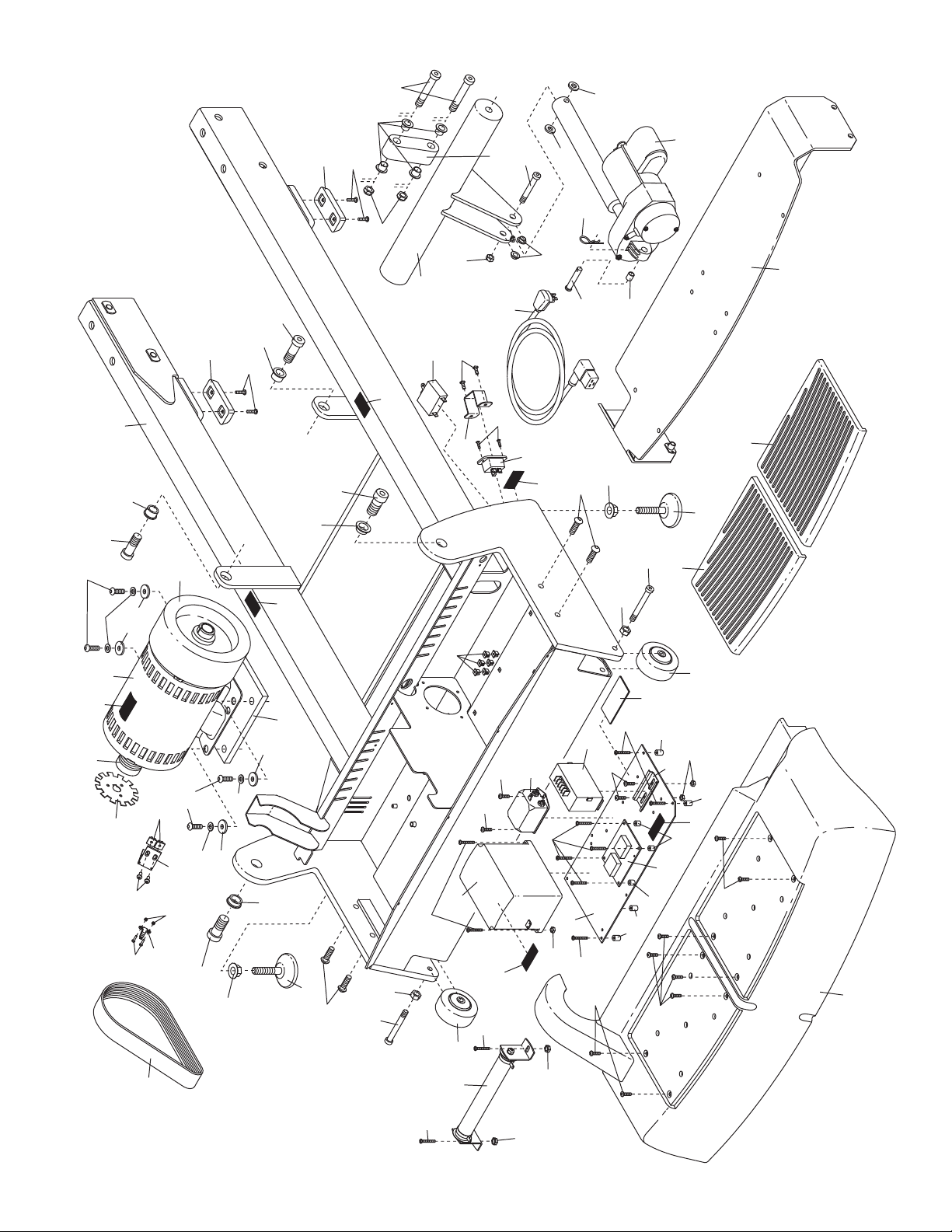
79
37
41
40
39
38
81
77
78
79
38
39
37
91
76
72
73
75
71
69
68
74
56
62
63
67
66
64
65
41
40
55
58
54
5
53
55
54
44
43
42
57
52
44
43
42
43
42
50
49
51
45
46
48
47
57
58
61
60
59
85
85
85
70
122
121
89
80
80
81
82
84
83
89
121
89
120
125
88
120
86
33
33
119
90
90
15
35
87
87
126
127
128
34
34
36
87
120
126
126
127
129
130
130
140
Part 2 of 4
46
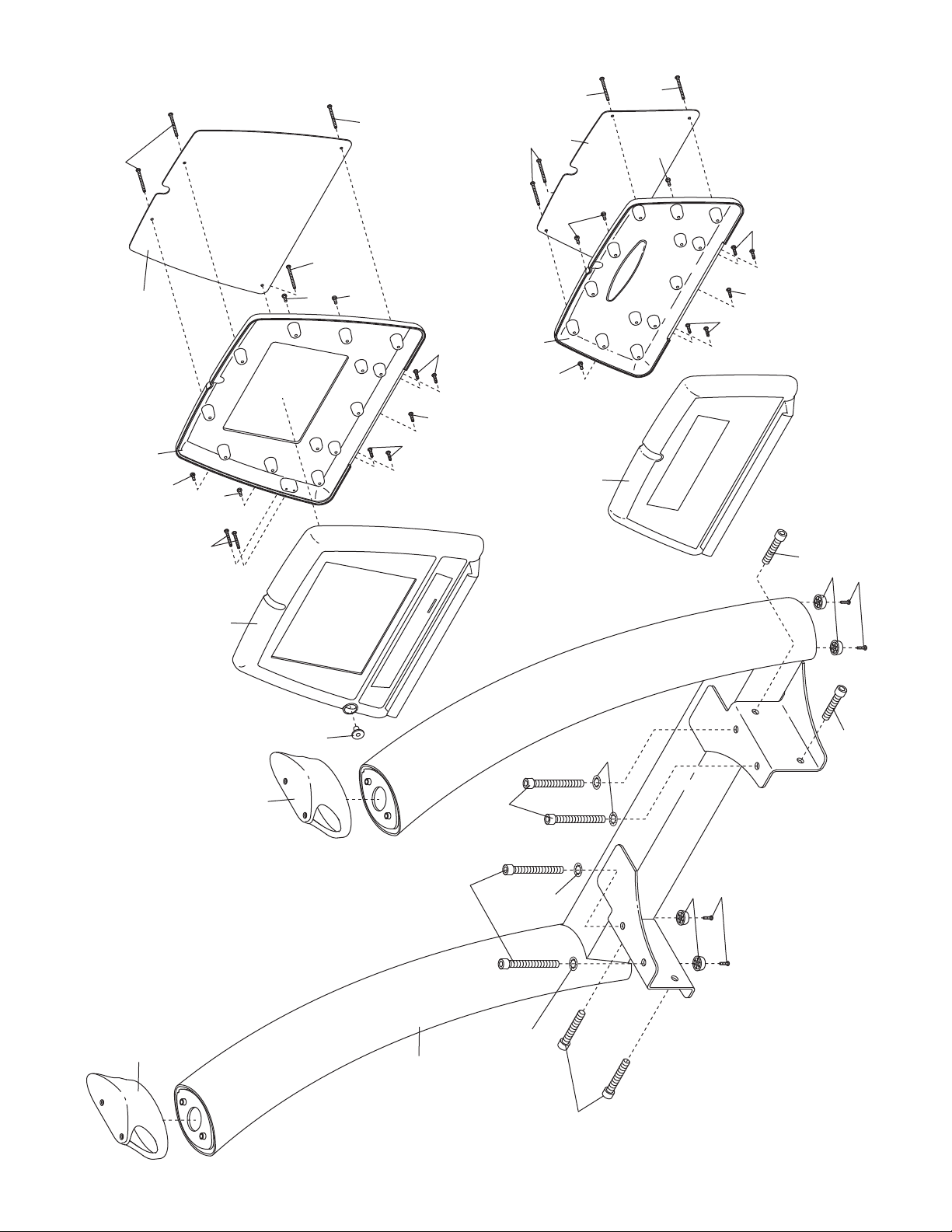
92
92
93
95
95
95
97
108
96
96
108
97
124
124
124
136
137
116
116
114
114
114
116
132
94
94
94
118
116
113
111
112
116
114
114
114
116
116
94
94
94
135
BASIC CONSOLE
TV CONSOLE
Part 3 of 4
47
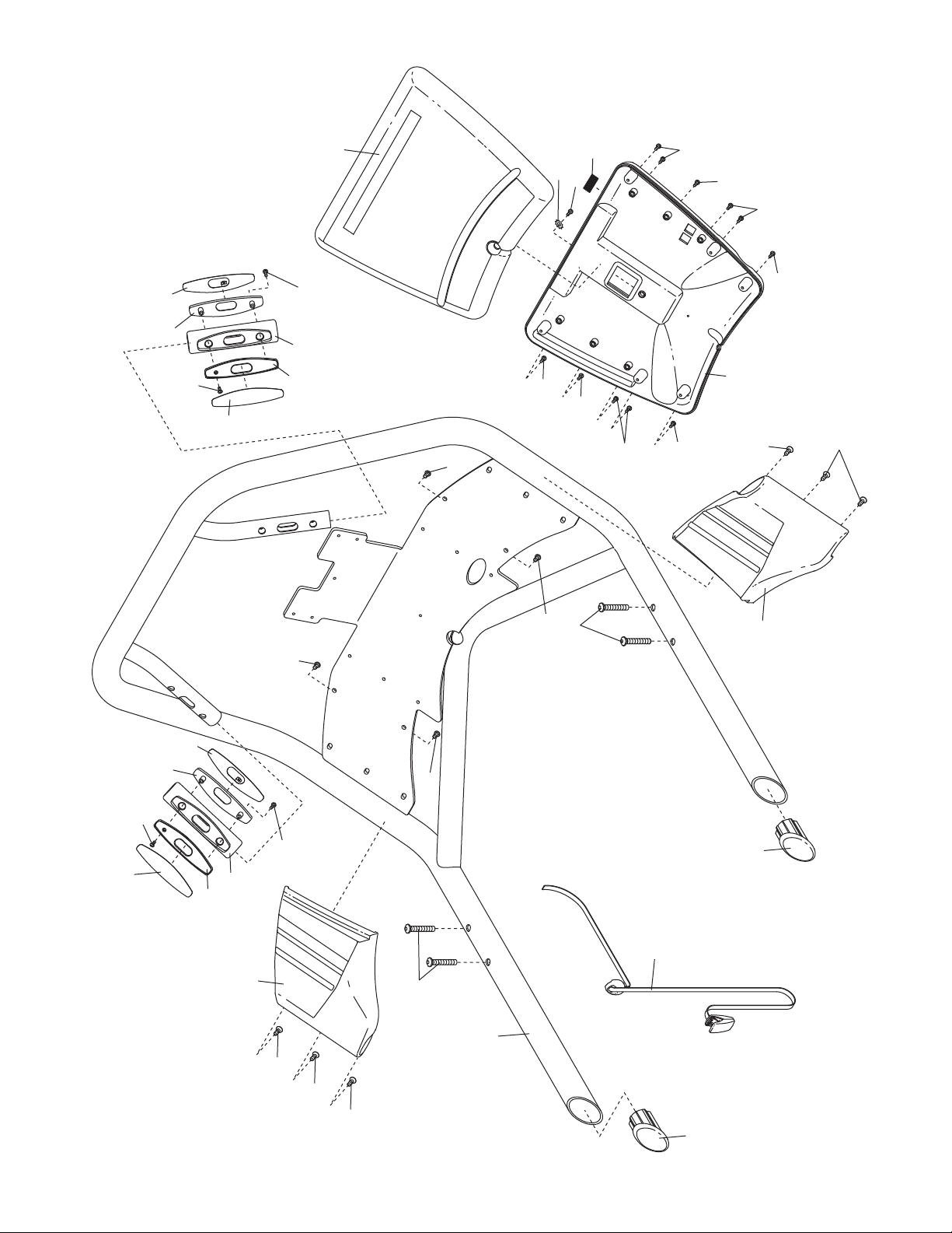
107
109
107
107
98
99
100
99
100
101
98
110
107
107
104
104
106
103
106
106
98
99
100
98
101
100
99
102
102
106
115
116
117
116
116
116
116
116
116
116
123
105
134
133
Part 4 of 4
48

49

FreeMotion Fitness, Inc.
Part No. CC7505 R0608A Printed in USA © 2008 ICON IP, Inc.
 Loading...