


NordicTrack CX 920 831.28353 User Manual
Model No. 831.283530
Serial No.___________
Serial Number
Decal
QUESTIONS?
As a manufacturer, we are com
mitted to providing complete
customer satisfaction. If you
have questions, or if there are
missing parts, we will guarantee
complete satisfaction through
direct assistance from our factory.
■ ®
USER’S MANUAL
TO AVOID DELAYS, PLEASE
CALL DIRECT TO OUR TOLL
FREE CUSTOMER HOT LINE. The
trained technicians on our cus
tomer hot line will provide imme
diate assistance, free of charge to
you.
CUSTOMER HOT LINE:
1-888-825-2588
Mon.-Fri., 6 a.m.-6 p.m. MST
A CAUTION
Read all precautions and instruc
tions in this manual before using
this equipment. Keep this manual
for future reference. ....................
Visit our website at
www.nordictrack.com
new products, prizes,
fitness tips, and much more!

TABLE OF CONTENTS
IMPORTANT PRECAUTIONS ...............................................................................................................................3
BEFORE YOU BEGIN ...........................................................................................................................................4
ASSEMBLY.............................................................................................................................................................5
HOW TO USE THE ELLIPTICAL CROSSTRAINER..............................................................................................9
MAINTENANCE AND TROUBLESHOOTING......................................................................................................20
CONDITIONING GUIDELINES ....................................................................................................................... 21
PART LIST............................................................................................................................................................22
EXPLODED DRAWING .......................................................................................................................................23
HOW TO ORDER REPLACEMENT PARTS ..........................................................................................Back Cover
LIMITED WARRANTY ............................................................................................................................ Back Cover
NordicTrack® is a registered trademark of ICON Health & Fitness, Inc.
IMPORTANT PRECAUTIONS
Awarning I To reduce the risk of serious injury, read the following important precau
tions before using the elliptical crosstrainer.
1.
Read alt instructions in this manual before
using the elliptical crosstrainer.
2.
It is the responsibility of the owner to ensure
that aU users of the elliptical crosstrainer
are adequately informed of all precautions.
3.
The elliptical crosstrainer is intended for
in-home use only. Do not use the elliptical
crosstrainer In any commercial, rental, or
institutional setting.
4.
Place the elliptical crosstrainer on a level
surface, with a mat beneath It to protect the
floor or carpet. Keep the elliptical crosstrain
er Indoors, away from moisture and dust.
5.
Inspect and tighten all parts regularly.
Replace any worn parts immediately.
12. The pulse sensor is not a medical device.
Various factors, Including the user's move
ment, may affect the accuracy of heart rate
readings. The pulse sensor is intended only
as an exercise aid In determining heart rate
trends in general.
13. When you stop exercising, allow the pedals
to slowly come to a complete stop. The ellip
tical crosstrainer does not have a free
wheel; the pedals will continue to move until
the flywheel stops.
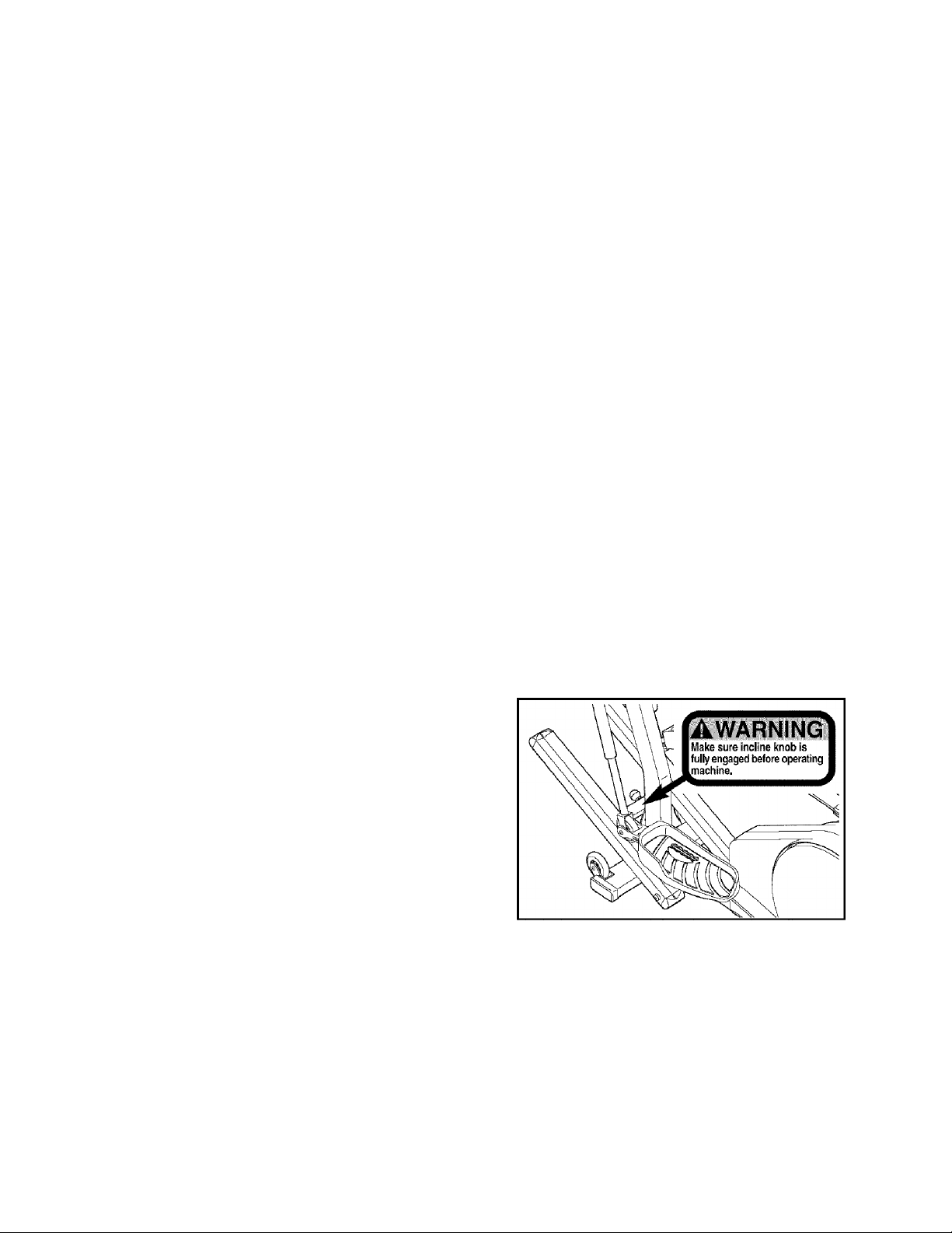
14. After adjusting the incline frame, move it up
or down slightly until the pin on the Incline
knob snaps Into one of the holes in the
incline bracket Push the incline knob to
make sure that the pin ts fully inserted into
the hole.
6.
Keep children under age 12 and pets away 15. The decal shown below has been placed on
from the elliptical crosstrainer at all times. ^ the elliptical crosstrainer. If the decal is
......................................................................missing or illegible, please call our Customer
7.
The elliptical crosstrainer should not be used Service Department toll-free at 1-888-825-
by persons weighing more than 250 pounds. 2588 to order a free replacement decal.
.......
Apply the decal in the location shown.
8.
Wear appropriate exercise clothing when
using the elliptical crosstrainer. Always wear
athletic shoes for foot protection.
9.
Always hold the handlebar or the upper
body arms when mounting, dismounting, or
using the elliptical crosstrainer.
10. Keep your back straight when using the ellip
tical crosstrainer. Do not arch your back.
11. If you feel pain or dizziness while exercis
ing, stop immediately and cool down.
A WARNING I Before beginning this or any exercise program, consult your physician.
This Is especially important for persons over the age of 35 or persons with pre-existing health prob
lems- Read all Instructions before using. ICON assumes no responsibility for personal injury or
property damage sustained by or through the use of this product.
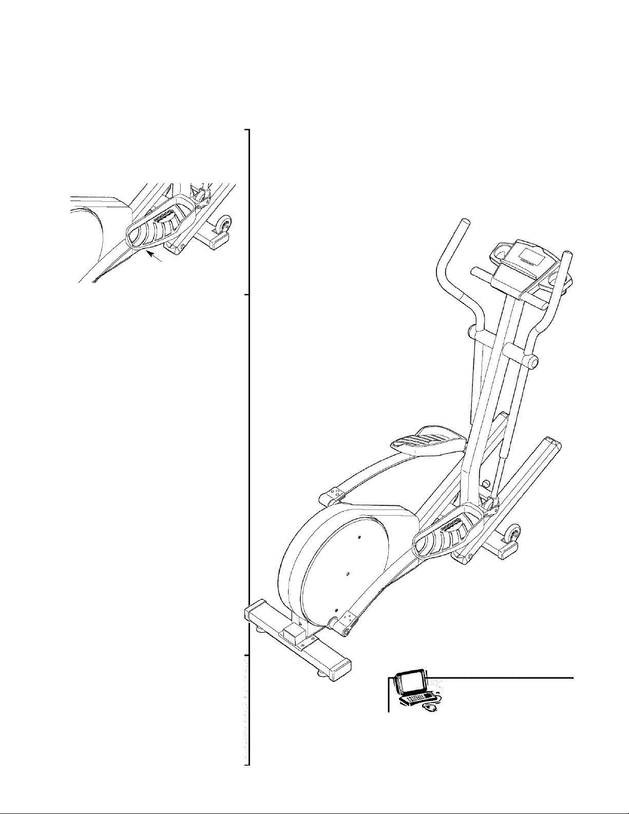
BEFORE YOU BEGIN
Congratulations for selecting the new NordicTrack®
CX 920 elliptical crosstrainer. The NordicTrack® CX 920
is an incredibly smooth exerciser that moves your feet
in a natural elliptical path, minimizing the impact on
your knees and ankles. And the unique CX 920 fea
tures adjustable resistance and incline to help you get
the most from your exercise. Welcome to a whole new
world of natural, elliptical-motion exercise from
NordicTrack.
For your benefit, read this manuai carefuiiy before you use the eiiipticai crosstrainer. If you have addi-
tional questions, please call our Customer Service
Department toll-free at 1-888-825-2588, Monday
through Friday, 6 a.m. until 6 p.m. Mountain Time
(excluding holidays). To help us assist you, please
note the product model number and serial number
before calling. The model number is 831.283530. The
serial number can be found on a decal attached to the
elliptical crosstrainer (see the front cover of this man
ual for the location of the decal).
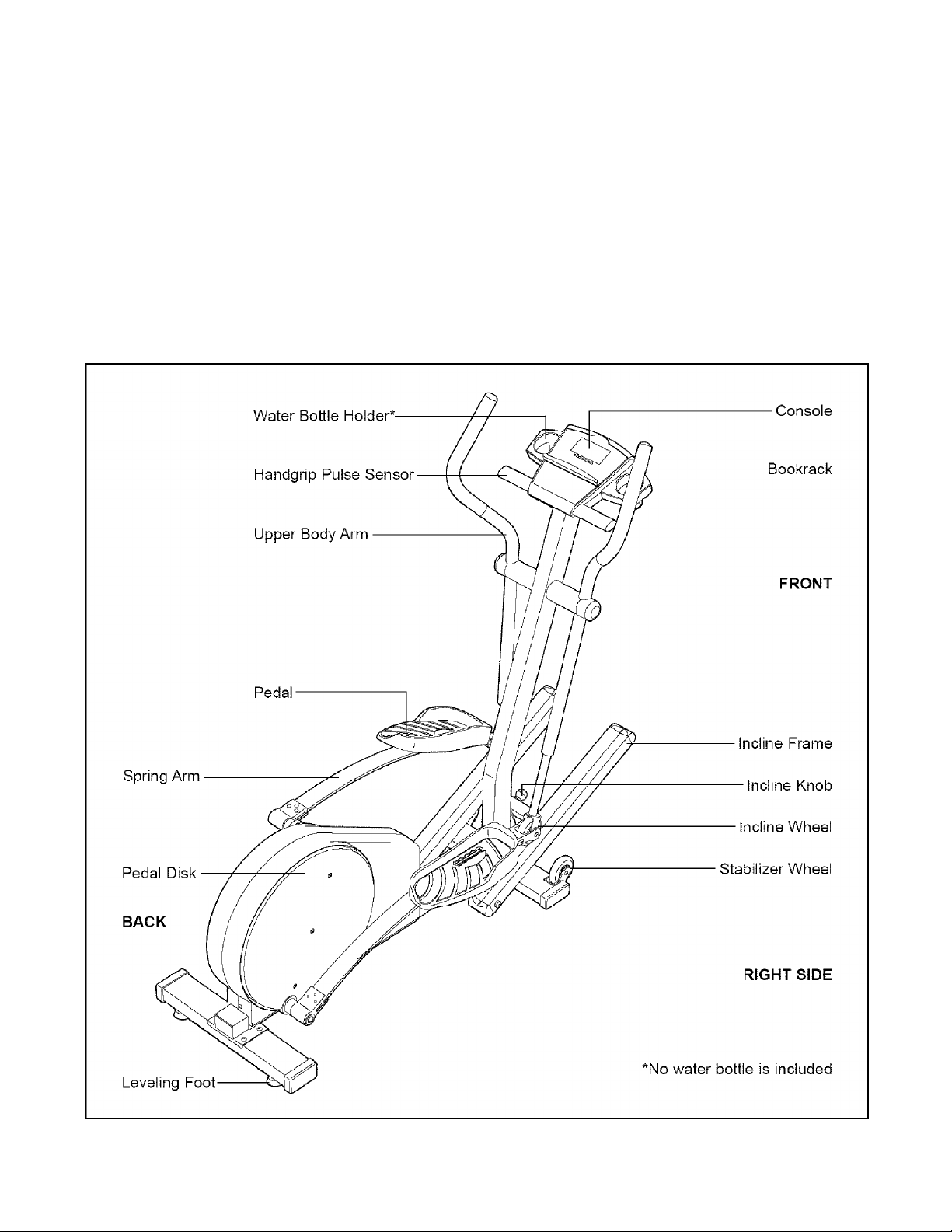
Before reading further, please familiarize yourself with
the parts that are labeled in the drawing below.

ASSEMBLY
Assembly requires two persons. Place all parts of the elliptical crosstrainer in a cleared area and remove the
packing materials. Do not dispose of the packing materials until assembly is completed. In addition to the
included alien wrenches, assembly requires a phillips screwdriver ^ , an adjustabie
wrench , a rubber mallet ,
As you assemble the elliptical crosstrainer, use the drawings below to identify the small parts used in assembly.
The number in parenthesis below each drawing refers to the key number of the part, from the PART LIST on
page 22. The second number refers to the quantity used in assembly. Note: Some small parts may have been
pre-assembled for shipping. If a part is not in the parts bag, check to see if it has been pre-assembied.
----------^_
|, and pliers
\ !
M8 Split
Washer (58)-2
M10 X 43mm Button Screw (97)-4
M10 X 56mm Button Screw (60)-4
M8 Washer (33)-2
M10 Split
Washer (22)-8
i \
M8 X 19mm Button
Screw (30)-2
Ml 0 X 33mm Carriage Bolt (61 )-2
Ml 0 Washer (63)-2
M10 Nylon Locknut (26)-4
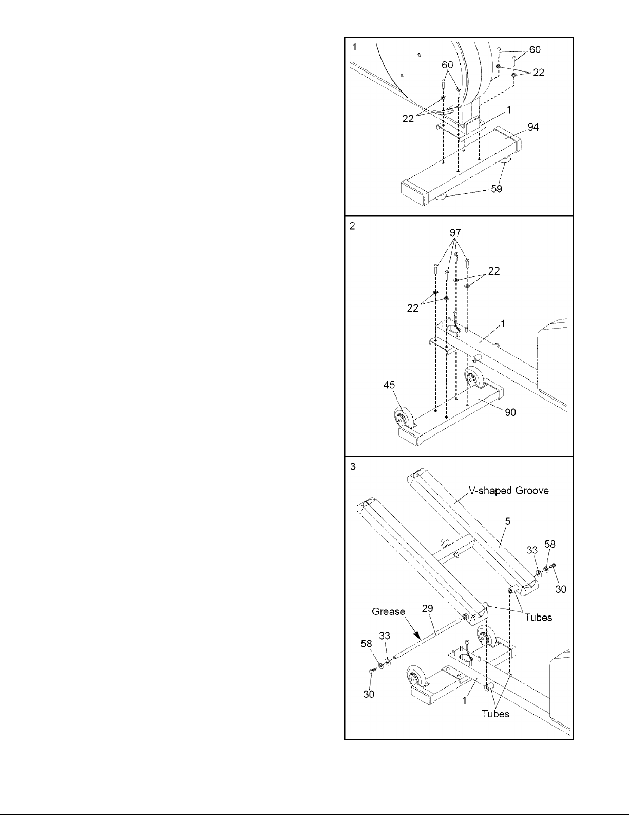
1. Identify the Rear Stabilizer (94), which has two Leveling
Feet (59) threaded into it. Turn the Rear Stabilizer so
the Leveling Feet are closer to the rear of the Frame
(1) as shown. Attach the Rear Stabilizer to the Frame
with the four MIO x 56mm Button Screws (60) and four
M10 Split Washers (22).
2. Attach the Front Stabilizer (90) to the Frame (1) with
the four M10 X 43mm Button Screws (97) and four
M10 Split Washers (22). Make sure that the Front
Stabilizer is turned so the Wheels (45) are not
touching the floor.
3. Slide an M8 Split Washer (58) and an M8 Washer (33)
onto an M8 X 19mm Button Screw (30). Tighten the
Button Screw into one end of the Incline Axle (29).
Next, apply a small amount of the included grease to
the Incline Axle,
Align the indicated tubes on the Incline Frame (5) with
the tubes on the Frame (1). Make sure that the
Incline Frame is turned so the V-shaped grooves
are on top. Insert the Incline Axle (29) through the
Incline Frame and the Frame. Note: It may be helpful
to tap the Incline Axle with a rubber mallet to insert it.
Slide an M8 Split Washer (58) and an M8 Washer (33)
onto the other IVI8 x 19mm Button Screw (30). Tighten
the Button Screw into the open end of the Incline Axle
(29).

4. The Console (87) requires four “D” batteries (not
included). Alkaline batteries are recommended. To
install batteries, turn the Console facedown and
remove the Battery Cover (84), as shown in the inset
drawing. Insert four batteries into the Console, Make
sure that the negative ends of the batteries
(marked “—”) are touching the springs in the
Console. Then, reattach the Battery Cover.
Connect the console wire harness to the Extension
Wire Harness (51). Carefully insert the slack in the
wire harnesses down into the Upright (2).
Attach the Console (87) to the Upright (2) with the four
Console Screws (35) and the four Console Washers
(93) packaged with the Console. Be careful to avoid
pinching the wire harnesses.
Snap the bookrack onto the Console (87) in the indi
cated location.
5. Remove the four MIO Nylon Locknuts (26) from the
welded bolts on the front of the Frame (1).
While a second person holds the Upright (2) near the
Frame (1), connect the Extension Wire Harness (51) to
the Wire Harness (85).
Align the four holes in the bracket on the lower end of
the Upright (2) with the welded bolts on the Frame (1).
Lower the Upright, feeding the slack in the
Extension Wire Harness (51) and Wire Harness (85)
into the Upright, until the welded bolts are inserted
into the bracket. Make sure that the Wire Harnesses
are not pinched. Tighten the four MIO Nylon Locknuts
(26) onto the welded bolts.
Adjust the Incline Frame (5) to the desired position
(see HOW TO ADJUST THE INCLINE FRAME on
page 9).
6. Identify the Left Pedal (41). Attach the Left Pedal to the
Left Spring Arm (3) with an MIO x 33mm Carriage Bolt
(61), an MIO Washer (63), and an Adjustment Knob
(77) as shown. Note: The Left Pedal can be attached
in any of five positions (see HOW TO ADJUST THE
PEDALS on page 9).
Attach the Right Pedal (not shown) in the same way.
Make sure that both Pedals are in the same position.

7. Apply a small amount of the included Teflon® lubricant
to a paper towel. Rub a thin film of the lubricant onto
the Chrome Tubes (21) on the Left and Right Spring
Arms (3, 4), Next, slide the Left Upper Body Arm (7),
which is marked with a sticker, onto the Chrome Tube
on the Left Spring Arm. Slide the Right Upper Body
Arm (75) onto the Chrome Tube on the Right Spring
Arm, Make sure that the Upper Body Arms are on
the correct sides—the upper ends should bend in
the direction shown by the arrows. Next, slide an
Axle Cover (74) onto the post on each Upper Body Arm.
Apply grease to the Arm Axle (19). Insert the Arm Axle
into the right Axle Cover (74) and the Right Upper Body
Arm (75). Next, insert the Arm Axle into the Upright (2)
until the left end of the Arm Axle is flush with the left
side of the Upright. Then, insert the Arm Axle into the
left Axle Cover (74) and the Left Upper Body Arm (7).
Center the Arm Axle (19). Using the included pedal
tool, tap two Push Nuts (15) about 1/8” onto each end
of the Arm Axle. Make sure that the Push Nuts are
turned as shown in the inset drawing. (Note: It may be
helpful if another person holds a block of wood against
one end of the Arm Axle while you tap Push Nuts onto
the other end.) Then, press an Axle Cap (34) onto each
end of the Arm Axle,
8. Make sure that all parts of the elliptical crosstrainer are properly tightened. Note: Some hardware may
be left over after assembly is completed.
INSTALLING THE RECEIVER FOR THE OPTIONAL CHEST PULSE SENSOR
If you purchase the optional chest pulse sensor (refer to
page 20), follow the steps below to install the receiver and
the short jumper wire included with the chest pulse sensor.
1. Remove the four indicated screws from the back of the
Console (87). Lift off the front of the Console.
2. Peel the paper off the adhesive pad on the back of the
receiver (A). Orient the receiver exactly as shown, and
press it onto the Console (87) in the indicated location.
Connect the short jumper wire (B) to the wire on the
receiver (A), Plug the other end of the short jumper wire
into either of the indicated jacks on the Console (87).
Note: The other wires included with the chest pulse sen
sor may be discarded.
Refer to step 1 above. Reattach the front of the
Console (87) with the four screws. Make sure that no
wires are pinched.
8
 Loading...