


MOTOROLA
SEMICONDUCTOR TECHNICAL DATA
Order this document by MC144110/D
Digital-to-Analog Converters with Serial Interface
CMOS LSI
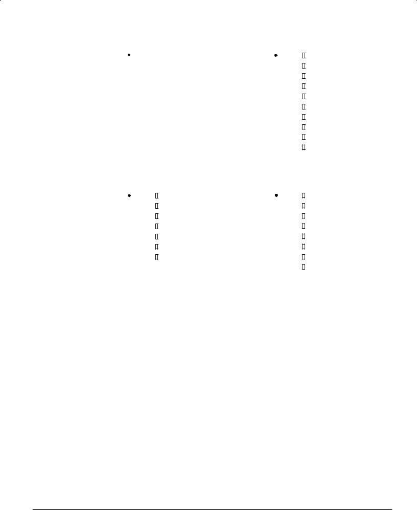
The MC144110 and MC144111 are low±cost 6±bit D/A converters with serial interface ports to provide communication with CMOS microprocessors and microcomputers. The MC144110 contains six static D/A converters; the MC144111 contains four converters.
Due to a unique feature of these DACs, the user is permitted easy scaling of the analog outputs of a system. Over a 5 to 15 V supply range, these DACs may be directly interfaced to CMOS MPUs operating at 5 V.
•Direct R±2R Network Outputs
•Buffered Emitter±Follower Outputs
•Serial Data Input
•Digital Data Output Facilitates Cascading
•Direct Interface to CMOS μP
•Wide Operating Voltage Range: 4.5 to 15 V
•Wide Operating Temperature Range: 0 to 85°C
•Software Information is Contained in Document M68HC11RM/AD
BLOCK DIAGRAM |
|
|
|
|||
VDD |
|
|
|
|
|
Qn Rn |
|
|
Q1 OUT |
|
R1 OUT |
OUT OUT |
|
2R |
|
|
|
|
|
|
|
R |
R |
R |
R |
R |
|
2R |
2R |
2R |
2R |
2R |
2R |
|
|
|
HEX BUFFER (INVERTING) |
|
|
||
MC144110
MC144111
MC144110
|
P SUFFIX |
|
PLASTIC DIP |
|
CASE 707 |
18 |
|
1 |
|
|
DW SUFFIX |
|
SOG PACKAGE |
20 |
CASE 751D |
|
|
1 |
|
MC144111 |
|
|
P SUFFIX |
|
PLASTIC DIP |
|
CASE 646 |
14 |
|
1 |
|
|
DW SUFFIX |
|
SOG PACKAGE |
16 |
CASE 751G |
1 |
|
ORDERING INFORMATION |
|
MC144110P |
Plastic DIP |
MC144110DW |
SOG Package |
MC144111P |
Plastic DIP |
MC144111DW |
SOG Package |
ENB |
|
CLK |
D * |
|
C Q |
Din
C |
HEX LATCH |
C |
6±BIT SHIFT REGISTER |
|
|
D |
Dout |
* Transparent Latch
REV 1 8/95
Motorola, Inc. 1995
MC144110P
|
Din |
|
1 |
18 |
|
VDD |
|
|
|
|
|||||
|
|
|
|||||
Q1 Out |
|
2 |
17 |
|
Dout |
||
|
|
||||||
R1 Out |
|
3 |
16 |
|
R6 Out |
||
Q2 Out |
|
4 |
15 |
|
Q6 Out |
||
|
|
||||||
R2 Out |
|
5 |
14 |
|
R5 Out |
||
|
|
||||||
Q3 Out |
|
6 |
13 |
|
Q5 Out |
||
|
|
||||||
R3 Out |
|
7 |
12 |
|
R4 Out |
||
|
|
||||||
|
|
|
|
8 |
11 |
|
Q4 Out |
|
ENB |
|
|
||||
|
|
|
|||||
|
VSS |
|
9 |
10 |
|
CLK |
|
|
|
|
|||||
|
|
|
|||||
MC144111P
|
Din |
|
1 |
14 |
VDD |
|
|
|
|||||
|
||||||
Q1 Out |
|
2 |
13 |
Dout |
||
|
||||||
R1 Out |
|
3 |
12 |
R4 Out |
||
Q2 Out |
|
4 |
11 |
Q4 Out |
||
|
||||||
R2 Out |
|
5 |
10 |
R3 Out |
||
|
||||||
|
|
|
|
|
|
|
ENB |
|
6 |
9 |
Q3 Out |
||
|
||||||
|
VSS |
|
7 |
8 |
CLK |
|
|
||||||
|
||||||
PIN ASSIGNMENTS
MC144110DW
|
Din |
|
1 |
20 |
VDD |
|
|
|
|||||
|
||||||
Q1 Out |
|
2 |
19 |
Dout |
||
|
||||||
R1 Out |
|
3 |
18 |
R6 Out |
||
Q2 Out |
|
4 |
17 |
Q6 Out |
||
|
||||||
R2 Out |
|
5 |
16 |
R5 Out |
||
|
||||||
Q3 Out |
|
6 |
15 |
Q5 Out |
||
|
||||||
|
|
|
|
7 |
14 |
R4 Out |
R3 Out |
|
|||||
|
||||||
|
|
|
8 |
13 |
Q4 Out |
|
ENB |
|
|||||
|
||||||
|
||||||
|
|
|
9 |
12 |
CLK |
|
|
VSS |
|
||||
|
||||||
|
NC |
|
10 |
11 |
NC |
|
|
|
|
|
|
|
|
MC144111DW
|
Din |
|
1 |
16 |
VDD |
|
|
|
|||||
|
||||||
Q1 Out |
|
2 |
15 |
Dout |
||
|
||||||
R1 Out |
|
3 |
14 |
R4 Out |
||
|
||||||
|
|
|
|
4 |
13 |
Q4 Out |
Q2 Out |
|
|||||
|
||||||
|
|
|
|
5 |
12 |
R3 Out |
R2 Out |
|
|||||
|
||||||
|
|
|
|
6 |
11 |
Q3 Out |
|
ENB |
|
||||
|
|
|||||
|
VSS |
|
7 |
10 |
CLK |
|
|
||||||
|
||||||
|
NC |
|
8 |
9 |
NC |
|
|
||||||
|
|
|
|
|
|
|
NC = NO CONNECTION
MC144110•MC144111 |
MOTOROLA |
2

MAXIMUM RATINGS* (Voltages referenced to VSS)
|
Parameter |
Symbol |
Value |
Unit |
|
|
|
|
|
DC Supply Voltage |
VDD |
± 0.5 to + 18 |
V |
|
Input Voltage, All Inputs |
Vin |
± 0.5 to VDD + 0.5 |
V |
|
DC Input Current, per Pin |
I |
± 10 |
mA |
|
|
|
|
|
|
Power Dissipation (Per Output) |
POH |
|
mW |
|
TA = 70°C, |
MC144110 |
|
30 |
|
|
MC144111 |
|
50 |
|
TA = 85°C, |
MC144110 |
|
10 |
|
|
MC144111 |
|
20 |
|
|
|
|
|
|
Power Dissipation (Per Package) |
PD |
|
mW |
|
TA = 70°C, |
MC144110 |
|
100 |
|
|
MC144111 |
|
150 |
|
TA = 85°C, |
MC144110 |
|
25 |
|
|
MC144111 |
|
50 |
|
|
|
|
|
|
Storage Temperature Range |
Tstg |
± 65 to + 150 |
°C |
|
* Maximum Ratings are those values beyond which damage to the device may occur.
This device contains protection circuitry to guard against damage due to high static voltages or electric fields; however, it is advised that precautions be taken to avoid application of voltage higher than maximum rated voltages to this high±impedance circuit. For proper operation it is recommended that Vin and Vout be constrained to the range VSS ≤
(Vin or Vout) ≤VDD.
Unused inputs must always be tied to an appropriate logic voltage level (e.g., either VSS or VDD).
ELECTRICAL CHARACTERISTICS (Voltages referenced to VSS, TA = 0 to 85°C unless otherwise indicated)
Symbol |
Parameter |
|
|
Test Conditions |
VDD |
Min |
Max |
Unit |
|
VIH |
High±Level Input Voltage (Din, ENB, CLK) |
|
5 |
3.0 |
Ð |
V |
|||
|
|
|
|
|
|
10 |
3.5 |
Ð |
|
|
|
|
|
|
|
15 |
4 |
Ð |
|
|
|
|
|
|
|
|
|
|
|
VIL |
Low±Level Input Voltage (Din, ENB, CLK) |
|
5 |
Ð |
0.8 |
V |
|||
|
|
|
|
|
|
10 |
Ð |
0.8 |
|
|
|
|
|
|
|
15 |
Ð |
0.8 |
|
|
|
|
|
|
|
|
|
|
|
IOH |
High±Level Output Current (Dout) |
Vout = VDD ± 0.5 V |
5 |
± 200 |
Ð |
μA |
|||
IOL |
Low±Level Output Current (Dout) |
Vout = 0.5 V |
5 |
200 |
Ð |
μA |
|||
IDD |
Quiescent Supply Current |
MC144110 |
Iout = 0 μA |
15 |
Ð |
12 |
mA |
||
|
|
|
MC144111 |
|
15 |
Ð |
8 |
|
|
|
|
|
|
|
|
|
|||
Iin |
Input Leakage Current (Din, ENB, CLK) |
Vin = VDD or 0 V |
15 |
Ð |
± 1 |
μA |
|||
Vnonl |
Nonlinearity Voltage (Rn Out) |
|
|
See Figure 1 |
5 |
Ð |
100 |
mV |
|
|
|
|
|
|
|
10 |
Ð |
200 |
|
|
|
|
|
|
|
15 |
Ð |
300 |
|
|
|
|
|
|
|
|
|
|
|
Vstep |
Step Size (Rn Out) |
|
|
See Figure 2 |
5 |
19 |
137 |
mV |
|
|
|
|
|
|
|
10 |
39 |
274 |
|
|
|
|
|
|
|
15 |
58 |
411 |
|
|
|
|
|
|
|
|
|
|
|
Voffset |
Offset Voltage from VSS |
|
|
Din = $00, See Figure 1 |
Ð |
Ð |
1 |
LSB |
|
IE |
Emitter Leakage Current |
|
|
VRn Out = 0 V |
15 |
Ð |
10 |
μA |
|
hFE |
DC Current Gain |
|
|
IE = 0.1 to 10.0 mA |
Ð |
40 |
Ð |
Ð |
|
|
|
|
|
|
TA = 25°C |
|
|
|
|
VBE |
Base±to±Emitter Voltage Drop |
|
|
IE = 1.0 mA |
Ð |
0.4 |
0.7 |
V |
|
MOTOROLA |
MC144110•MC144111 |
3
 Loading...