


Operation
Automatic Transfer Switches
Controls:
Decision-Makerr MPAC 1500
Transfer Switch Models:
KCS/KCP/KCC
KBS/KBP/KBC
KAS/KAP
KGS/KGP
KEP
TP-6883 4/21d
|
|
Table of Contents |
|
|
|
||
Safety Precautions and Instructions . . . . . . . . . . . . . . . . . . . . . . . . . . . . . . . . . . . . . . . . . . . . . . . . . . . . . . . . |
7 |
||
Introduction . . . . . . . . |
. . . . . . . . . |
. . . . . . . . . . . . . . . . . . . . . . . . . . . . . . . . . . . . . . . . . . . . . . . . . . . . . . . . . . . . . |
9 |
List of Related Materials . . . . . . . . . . . . . . . . . . . . . . . . . . . . . . . . . . . . . . . . . . . . . . . . . . . . . |
9 |
||
Service Assistance . . . |
. . . . . . . . |
. . . . . . . . . . . . . . . . . . . . . . . . . . . . . . . . . . . . . . . . . . . . . . . . . . . . . . . . . . . . . |
10 |
Section 1 Operation . . |
. . . . . . . . |
. . . . . . . . . . . . . . . . . . . . . . . . . . . . . . . . . . . . . . . . . . . . . . . . . . . . . . . . . . . . . |
11 |
1.1 |
Introduction . . . . . . . . . . . . . . . . . . . . . . . . . . . . . . . . . . . . . . . . . . . . . . . . . . . . . . . . . . |
11 |
|
1.2 |
Source Names . . . . . . . . . . . . . . . . . . . . . . . . . . . . . . . . . . . . . . . . . . . . . . . . . . . . . . . . |
11 |
|
1.3 |
User Interface Panel . . . . . . . . . . . . . . . . . . . . . . . . . . . . . . . . . . . . . . . . . . . . . . . . . . . |
11 |
|
|
1.3.1 |
Display . . . . . . . . . . . . . . . . . . . . . . . . . . . . . . . . . . . . . . . . . . . . . . . . . . . . . . |
12 |
|
1.3.2 |
Display Contrast . . . . . . . . . . . . . . . . . . . . . . . . . . . . . . . . . . . . . . . . . . . . . . |
12 |
|
1.3.3 |
Pushbuttons . . . . . . . . . . . . . . . . . . . . . . . . . . . . . . . . . . . . . . . . . . . . . . . . . . |
12 |
|
1.3.4 |
LED Indicators . . . . . . . . . . . . . . . . . . . . . . . . . . . . . . . . . . . . . . . . . . . . . . . . |
13 |
|
1.3.5 |
Lamp Test . . . . . . . . . . . . . . . . . . . . . . . . . . . . . . . . . . . . . . . . . . . . . . . . . . . . |
13 |
|
1.3.6 |
Examples . . . . . . . . . . . . . . . . . . . . . . . . . . . . . . . . . . . . . . . . . . . . . . . . . . . . |
13 |
1.4 |
Main Menu . . . . . . . . . . . . . . . . . . . . . . . . . . . . . . . . . . . . . . . . . . . . . . . . . . . . . . . . . . . |
15 |
|
1.5 |
Passwords . . . . . . . . . . . . . . . . . . . . . . . . . . . . . . . . . . . . . . . . . . . . . . . . . . . . . . . . . . . |
16 |
|
|
1.5.1 |
Changing Passwords . . . . . . . . . . . . . . . . . . . . . . . . . . . . . . . . . . . . . . . . . . |
16 |
|
1.5.2 |
Test Password Reset and Disable . . . . . . . . . . . . . . . . . . . . . . . . . . . . . . . |
16 |
1.6 |
Normal Operation Menus . . . . . . . . . . . . . . . . . . . . . . . . . . . . . . . . . . . . . . . . . . . . . . |
17 |
|
1.7 |
System Test . . . . . . . . . . . . . . . . . . . . . . . . . . . . . . . . . . . . . . . . . . . . . . . . . . . . . . . . . . |
18 |
|
|
1.7.1 |
Unloaded System Test . . . . . . . . . . . . . . . . . . . . . . . . . . . . . . . . . . . . . . . . . |
19 |
|
1.7.2 |
Loaded System Test . . . . . . . . . . . . . . . . . . . . . . . . . . . . . . . . . . . . . . . . . . . |
19 |
|
1.7.3 |
Closed-Transition Loaded Test . . . . . . . . . . . . . . . . . . . . . . . . . . . . . . . . . . |
19 |
|
1.7.4 |
Auto-Loaded System Test . . . . . . . . . . . . . . . . . . . . . . . . . . . . . . . . . . . . . . |
20 |
|
1.7.5 |
Sync Check (closed-transition) . . . . . . . . . . . . . . . . . . . . . . . . . . . . . . . . . . |
20 |
1.8 |
Automatic Operation Test . . . . . . . . . . . . . . . . . . . . . . . . . . . . . . . . . . . . . . . . . . . . . . |
20 |
|
1.9 |
Exercise |
. . . . . . . . . . . . . . . . . . . . . . . . . . . . . . . . . . . . . . . . . . . . . . . . . . . . . . . . . . . . . |
23 |
|
1.9.1 |
Unloaded Exercise . . . . . . . . . . . . . . . . . . . . . . . . . . . . . . . . . . . . . . . . . . . . |
23 |
|
1.9.2 |
Load Bank Control . . . . . . . . . . . . . . . . . . . . . . . . . . . . . . . . . . . . . . . . . . . . |
23 |
|
1.9.3 |
Loaded Exercise . . . . . . . . . . . . . . . . . . . . . . . . . . . . . . . . . . . . . . . . . . . . . . |
23 |
1.10 |
Warnings and Faults . . . . . . . . . . . . . . . . . . . . . . . . . . . . . . . . . . . . . . . . . . . . . . . . . . . |
24 |
|
|
1.10.1 |
Fault Reset . . . . . . . . . . . . . . . . . . . . . . . . . . . . . . . . . . . . . . . . . . . . . . . . . . . |
25 |
1.11 |
Accessory Module Faults . . . . . . . . . . . . . . . . . . . . . . . . . . . . . . . . . . . . . . . . . . . . . . |
25 |
|
|
1.11.1 |
Module Status Change . . . . . . . . . . . . . . . . . . . . . . . . . . . . . . . . . . . . . . . . . |
25 |
|
1.11.2 |
Module Status Conflict . . . . . . . . . . . . . . . . . . . . . . . . . . . . . . . . . . . . . . . . . |
26 |
1.12 |
Reset Data . . . . . . . . . . . . . . . . . . . . . . . . . . . . . . . . . . . . . . . . . . . . . . . . . . . . . . . . . . . |
27 |
|
|
1.12.1 |
Reset Maintenance Records . . . . . . . . . . . . . . . . . . . . . . . . . . . . . . . . . . . . |
27 |
|
1.12.2 |
Reset Event History . . . . . . . . . . . . . . . . . . . . . . . . . . . . . . . . . . . . . . . . . . . |
27 |
|
1.12.3 |
Reset Default Parameters . . . . . . . . . . . . . . . . . . . . . . . . . . . . . . . . . . . . . . |
28 |
|
1.12.4 |
Reset and Disable Test Password . . . . . . . . . . . . . . . . . . . . . . . . . . . . . . . |
28 |
Section 2 Sequence of Operation . . . . . . . . . . . . . . . . . . . . . . . . . . . . . . . . . . . . . . . . . . . . . . . . . . . . . . . . . . |
29 |
||
2.1 |
Controller Power-up/Reset . . . . . . . . . . . . . . . . . . . . . . . . . . . . . . . . . . . . . . . . . . . . . |
29 |
|
2.2 |
Sequence of Operation, Standard Transition Models . . . . . . . . . . . . . . . . . . . . . . . |
30 |
|
|
2.2.1 |
Preferred Source Loss and Return, Standard Transition . . . . . . . . . . . . |
30 |
|
2.2.2 |
Exerciser Operation, Standard Transition . . . . . . . . . . . . . . . . . . . . . . . . . |
30 |
|
2.2.3 |
Test Sequence, Standard Transition . . . . . . . . . . . . . . . . . . . . . . . . . . . . . |
31 |
2.3 |
Sequence of Operation, Programmed-Transition . . . . . . . . . . . . . . . . . . . . . . . . . . |
32 |
|
|
2.3.1 |
Preferred Source Loss and Return, Programmed Transition . . . . . . . . . |
32 |
|
2.3.2 |
Exerciser Operation, Programmed Transition . . . . . . . . . . . . . . . . . . . . . |
32 |
|
2.3.3 |
Test Sequence, Programmed Transition . . . . . . . . . . . . . . . . . . . . . . . . . . |
33 |
TP-6883 4/21 |
Table of Contents 3 |

Table of Contents, continued
2.4 Sequence of Operation, Closed-Transition Models . . . . . . . . . . . . . . . . . . . . . . . . . 34 2.4.1 Preferred Source Loss and Return, Closed Transition . . . . . . . . . . . . . . 34 2.4.2 Failure to Synchronize (Programmed-Transition Override) . . . . . . . . . . 34 2.4.3 Exerciser Operation, Closed Transition . . . . . . . . . . . . . . . . . . . . . . . . . . . 35 2.4.4 Test Sequence, Closed Transition . . . . . . . . . . . . . . . . . . . . . . . . . . . . . . . 35 2.4.5 Extended Transfer Time Relay . . . . . . . . . . . . . . . . . . . . . . . . . . . . . . . . . . 36
2.5 Sequence of Operation, Service Entrance Models . . . . . . . . . . . . . . . . . . . . . . . . . 37 2.5.1 Preferred Source Loss and Return, Service Entrance Models . . . . . . . 37
2.5.2Exerciser Operation,
Service Entrance Models . . . . . . . . . . . . . . . . . . . . . . . . . . . . . . . . . . . . . . . 37
2.5.3Test Sequence,
Service Entrance Models . . . . . . . . . . . . . . . . . . . . . . . . . . . . . . . . . . . . . . . 38
Section 3 View Screens . . . . . . . . . . . . . . . . . . . . . . . . . . . . . . . . . . . . . . . . . . . . . . . . . . . . . . . . . . . . . . . . . . . |
39 |
|
3.1 |
Introduction . . . . . . . . . . . . . . . . . . . . . . . . . . . . . . . . . . . . . . . . . . . . . . . . . . . . . . . . . . |
39 |
3.2 |
Main Screen . . . . . . . . . . . . . . . . . . . . . . . . . . . . . . . . . . . . . . . . . . . . . . . . . . . . . . . . . . |
39 |
3.3 |
View Screens . . . . . . . . . . . . . . . . . . . . . . . . . . . . . . . . . . . . . . . . . . . . . . . . . . . . . . . . . |
39 |
3.4 |
View Event History . . . . . . . . . . . . . . . . . . . . . . . . . . . . . . . . . . . . . . . . . . . . . . . . . . . . |
40 |
3.5 |
View Maintenance Records . . . . . . . . . . . . . . . . . . . . . . . . . . . . . . . . . . . . . . . . . . . . . |
40 |
3.6 |
View Exerciser Setup . . . . . . . . . . . . . . . . . . . . . . . . . . . . . . . . . . . . . . . . . . . . . . . . . . |
41 |
3.7 |
View Prime Power Setup . . . . . . . . . . . . . . . . . . . . . . . . . . . . . . . . . . . . . . . . . . . . . . . |
41 |
3.8 |
View System Setup . . . . . . . . . . . . . . . . . . . . . . . . . . . . . . . . . . . . . . . . . . . . . . . . . . . |
41 |
3.9 |
View Source Setup . . . . . . . . . . . . . . . . . . . . . . . . . . . . . . . . . . . . . . . . . . . . . . . . . . . . |
42 |
3.10 |
View Time Delays, Source 1 . . . . . . . . . . . . . . . . . . . . . . . . . . . . . . . . . . . . . . . . . . . . |
44 |
3.11 |
View Time Delays, Source 2 . . . . . . . . . . . . . . . . . . . . . . . . . . . . . . . . . . . . . . . . . . . . |
46 |
3.12 |
View Inputs/Outputs . . . . . . . . . . . . . . . . . . . . . . . . . . . . . . . . . . . . . . . . . . . . . . . . . . . |
48 |
3.13 |
View Common Alarms . . . . . . . . . . . . . . . . . . . . . . . . . . . . . . . . . . . . . . . . . . . . . . . . . |
48 |
3.14 |
View Communications Setup . . . . . . . . . . . . . . . . . . . . . . . . . . . . . . . . . . . . . . . . . . . |
49 |
3.15 |
View Control Parameters . . . . . . . . . . . . . . . . . . . . . . . . . . . . . . . . . . . . . . . . . . . . . . . |
49 |
Section 4 Setup . . . . . |
. . . . . . . . |
. . . . . . . . . . . . . . . . . . . . . . . . . . . . . . . . . . . . . . . . . . . . . . . . . . . . . . . . . . . . . . |
51 |
4.1 |
Introduction . . . . . . . . . . . . . . . . . . . . . . . . . . . . . . . . . . . . . . . . . . . . . . . . . . . . . . . . . . |
51 |
|
4.2 |
Setup Menus . . . . . . . . . . . . . . . . . . . . . . . . . . . . . . . . . . . . . . . . . . . . . . . . . . . . . . . . . |
51 |
|
4.3 |
Time/Date . . . . . . . . . . . . . . . . . . . . . . . . . . . . . . . . . . . . . . . . . . . . . . . . . . . . . . . . . . . . |
52 |
|
4.4 |
Exerciser . . . . . . . . . . . . . . . . . . . . . . . . . . . . . . . . . . . . . . . . . . . . . . . . . . . . . . . . . . . . |
53 |
|
|
4.4.1 |
Setting the Exerciser . . . . . . . . . . . . . . . . . . . . . . . . . . . . . . . . . . . . . . . . . . |
53 |
|
4.4.2 |
Source/Source Mode . . . . . . . . . . . . . . . . . . . . . . . . . . . . . . . . . . . . . . . . . . |
53 |
4.5 |
Prime Power Run . . . . . . . . . . . . . . . . . . . . . . . . . . . . . . . . . . . . . . . . . . . . . . . . . . . . . |
55 |
|
|
4.5.1 |
Prime Power Mode Setup . . . . . . . . . . . . . . . . . . . . . . . . . . . . . . . . . . . . . . |
55 |
|
4.5.2 |
Prime Power Mode Operation . . . . . . . . . . . . . . . . . . . . . . . . . . . . . . . . . . . |
55 |
4.6 |
Time Delays . . . . . . . . . . . . . . . . . . . . . . . . . . . . . . . . . . . . . . . . . . . . . . . . . . . . . . . . . . |
56 |
|
|
4.6.1 |
Time Delays . . . . . . . . . . . . . . . . . . . . . . . . . . . . . . . . . . . . . . . . . . . . . . . . . . |
56 |
|
4.6.2 |
Load Control Time Delays . . . . . . . . . . . . . . . . . . . . . . . . . . . . . . . . . . . . . . |
56 |
|
4.6.3 |
Set S1 Time Delays . . . . . . . . . . . . . . . . . . . . . . . . . . . . . . . . . . . . . . . . . . . |
57 |
|
4.6.4 |
Set S2 Time Delays . . . . . . . . . . . . . . . . . . . . . . . . . . . . . . . . . . . . . . . . . . . |
59 |
4.7 |
Load Control . . . . . . . . . . . . . . . . . . . . . . . . . . . . . . . . . . . . . . . . . . . . . . . . . . . . . . . . . |
61 |
|
|
4.7.1 |
Time-Based Load Control . . . . . . . . . . . . . . . . . . . . . . . . . . . . . . . . . . . . . . |
61 |
|
4.7.2 |
Current-Based Load Control . . . . . . . . . . . . . . . . . . . . . . . . . . . . . . . . . . . . |
63 |
4.8 |
Set Sources . . . . . . . . . . . . . . . . . . . . . . . . . . . . . . . . . . . . . . . . . . . . . . . . . . . . . . . . . . |
65 |
|
|
4.8.1 |
Phase Rotation . . . . . . . . . . . . . . . . . . . . . . . . . . . . . . . . . . . . . . . . . . . . . . . |
65 |
|
4.8.2 |
In-Phase Monitor . . . . . . . . . . . . . . . . . . . . . . . . . . . . . . . . . . . . . . . . . . . . . . |
65 |
|
4.8.3 |
Preferred Source Selection . . . . . . . . . . . . . . . . . . . . . . . . . . . . . . . . . . . . . |
65 |
|
4.8.4 |
System Voltage and Frequency . . . . . . . . . . . . . . . . . . . . . . . . . . . . . . . . . |
67 |
|
4.8.5 |
Voltage and Frequency Pickup and Dropout Settings . . . . . . . . . . . . . . . |
67 |
|
4.8.6 |
Set Sources . . . . . . . . . . . . . . . . . . . . . . . . . . . . . . . . . . . . . . . . . . . . . . . . . . |
68 |
4 Table of Contents |
TP-6883 4/21 |

Table of Contents, continued
4.9 |
Inputs and Outputs . . . . . . . . . . . . . . . . . . . . . . . . . . . . . . . . . . . . . . . . . . . . . . . . . . . . |
71 |
|
|
4.9.1 |
Controller Inputs and Outputs . . . . . . . . . . . . . . . . . . . . . . . . . . . . . . . . . . . |
71 |
|
4.9.2 |
Input/Output Modules . . . . . . . . . . . . . . . . . . . . . . . . . . . . . . . . . . . . . . . . . . |
71 |
|
4.9.3 |
Input Functions . . . . . . . . . . . . . . . . . . . . . . . . . . . . . . . . . . . . . . . . . . . . . . . |
72 |
|
4.9.4 |
Output Functions . . . . . . . . . . . . . . . . . . . . . . . . . . . . . . . . . . . . . . . . . . . . . . |
73 |
|
4.9.5 |
User-Defined I/O Descriptions . . . . . . . . . . . . . . . . . . . . . . . . . . . . . . . . . . |
74 |
4.10 |
Common Alarms . . . . . . . . . . . . . . . . . . . . . . . . . . . . . . . . . . . . . . . . . . . . . . . . . . . . . . |
75 |
|
|
4.10.1 |
Common Alarm Output . . . . . . . . . . . . . . . . . . . . . . . . . . . . . . . . . . . . . . . . |
75 |
|
4.10.2 |
Audible Alarm . . . . . . . . . . . . . . . . . . . . . . . . . . . . . . . . . . . . . . . . . . . . . . . . |
75 |
|
4.10.3 |
Chicago Alarm . . . . . . . . . . . . . . . . . . . . . . . . . . . . . . . . . . . . . . . . . . . . . . . . |
75 |
4.11 |
Set System . . . . . . . . . . . . . . . . . . . . . . . . . . . . . . . . . . . . . . . . . . . . . . . . . . . . . . . . . . |
76 |
|
|
4.11.1 |
Default Settings . . . . . . . . . . . . . . . . . . . . . . . . . . . . . . . . . . . . . . . . . . . . . . . |
76 |
|
4.11.2 |
Source Type/Source Type . . . . . . . . . . . . . . . . . . . . . . . . . . . . . . . . . . . . . . |
76 |
|
4.11.3 |
Transition Type . . . . . . . . . . . . . . . . . . . . . . . . . . . . . . . . . . . . . . . . . . . . . . . |
76 |
|
4.11.4 |
Service Entrance . . . . . . . . . . . . . . . . . . . . . . . . . . . . . . . . . . . . . . . . . . . . . . |
78 |
|
4.11.5 |
Rated Current . . . . . . . . . . . . . . . . . . . . . . . . . . . . . . . . . . . . . . . . . . . . . . . . |
78 |
|
4.11.6 |
Three Source Engine Start Mode . . . . . . . . . . . . . . . . . . . . . . . . . . . . . . . . |
78 |
|
4.11.7 |
Transfer Commit . . . . . . . . . . . . . . . . . . . . . . . . . . . . . . . . . . . . . . . . . . . . . . |
78 |
|
4.11.8 |
Remote Test Loading . . . . . . . . . . . . . . . . . . . . . . . . . . . . . . . . . . . . . . . . . . |
78 |
|
4.11.9 |
Peak Shave TD Bypass . . . . . . . . . . . . . . . . . . . . . . . . . . . . . . . . . . . . . . . . |
78 |
4.12 |
Three-Source Systems . . . . . . . . . . . . . . . . . . . . . . . . . . . . . . . . . . . . . . . . . . . . . . . . |
79 |
|
|
4.12.1 |
Three Source Engine Start Mode . . . . . . . . . . . . . . . . . . . . . . . . . . . . . . . . |
79 |
|
4.12.2 |
Preferred Source Toggle . . . . . . . . . . . . . . . . . . . . . . . . . . . . . . . . . . . . . . . |
79 |
|
4.12.3 |
Three Source System Test and Exercise . . . . . . . . . . . . . . . . . . . . . . . . . |
79 |
|
4.12.4 |
Three-Source System Setup . . . . . . . . . . . . . . . . . . . . . . . . . . . . . . . . . . . . |
81 |
|
4.12.5 |
ATS1 and ATS2 System Setup . . . . . . . . . . . . . . . . . . . . . . . . . . . . . . . . . . |
81 |
4.13 |
Communications . . . . . . . . . . . . . . . . . . . . . . . . . . . . . . . . . . . . . . . . . . . . . . . . . . . . . . |
83 |
|
4.14 |
Set Passwords . . . . . . . . . . . . . . . . . . . . . . . . . . . . . . . . . . . . . . . . . . . . . . . . . . . . . . . |
83 |
|
4.15 |
Calibration . . . . . . . . . . . . . . . . . . . . . . . . . . . . . . . . . . . . . . . . . . . . . . . . . . . . . . . . . . . |
84 |
|
4.16 |
Setting the Current to Zero . . . . . . . . . . . . . . . . . . . . . . . . . . . . . . . . . . . . . . . . . . . . . |
84 |
|
4.17 |
Reset Data . . . . . . . . . . . . . . . . . . . . . . . . . . . . . . . . . . . . . . . . . . . . . . . . . . . . . . . . . . . |
84 |
|
Section 5 Communications . . |
. . . . . . . . . . . . . . . . . . . . . . . . . . . . . . . . . . . . . . . . . . . . . . . . . . . . . . . . . . . . . . |
85 |
|
5.1 |
Introduction . . . . . . . . . . . . . . . . . . . . . . . . . . . . . . . . . . . . . . . . . . . . . . . . . . . . . . . . . . |
85 |
|
5.2 |
Connections . . . . . . . . . . . . . . . . . . . . . . . . . . . . . . . . . . . . . . . . . . . . . . . . . . . . . . . . . . |
85 |
|
|
5.2.1 |
USB Port SiteTech Connection . . . . . . . . . . . . . . . . . . . . . . . . . . . . . . . . . . |
85 |
|
5.2.2 |
Modbus Connection . . . . . . . . . . . . . . . . . . . . . . . . . . . . . . . . . . . . . . . . . . . |
86 |
|
5.2.3 |
Ethernet Connection . . . . . . . . . . . . . . . . . . . . . . . . . . . . . . . . . . . . . . . . . . . |
86 |
5.3 |
Communications Setup . . . . . . . . . . . . . . . . . . . . . . . . . . . . . . . . . . . . . . . . . . . . . . . . |
87 |
|
|
5.3.1 |
Modbus Serial Communication Setup . . . . . . . . . . . . . . . . . . . . . . . . . . . . |
87 |
|
5.3.2 |
Network Communication Setup . . . . . . . . . . . . . . . . . . . . . . . . . . . . . . . . . |
87 |
|
5.3.3 |
Setup Using the Controller Keypad . . . . . . . . . . . . . . . . . . . . . . . . . . . . . . |
87 |
|
5.3.4 |
Setup Using SiteTech . . . . . . . . . . . . . . . . . . . . . . . . . . . . . . . . . . . . . . . . . . |
87 |
5.4 |
Parameter Files . . . . . . . . . . . . . . . . . . . . . . . . . . . . . . . . . . . . . . . . . . . . . . . . . . . . . . . |
91 |
|
5.5 |
Controller Firmware Updates . . . . . . . . . . . . . . . . . . . . . . . . . . . . . . . . . . . . . . . . . . . |
91 |
|
Section 6 Scheduled Maintenance . . . . . . . . . . . . . . . . . . . . . . . . . . . . . . . . . . . . . . . . . . . . . . . . . . . . . . . . . . |
93 |
||
6.1 |
Introduction . . . . . . . . . . . . . . . . . . . . . . . . . . . . . . . . . . . . . . . . . . . . . . . . . . . . . . . . . . |
93 |
|
6.2 |
Testing . |
. . . . . . . . . . . . . . . . . . . . . . . . . . . . . . . . . . . . . . . . . . . . . . . . . . . . . . . . . . . . . |
94 |
|
6.2.1 |
Weekly Generator Set Exercise . . . . . . . . . . . . . . . . . . . . . . . . . . . . . . . . . |
94 |
|
6.2.2 |
Monthly Automatic Control System Test . . . . . . . . . . . . . . . . . . . . . . . . . . |
94 |
TP-6883 4/21 |
Table of Contents 5 |

Table of Contents, continued
6.3 |
Inspection and Service . . . . . . . . . . . . . . . . . . . . . . . . . . . . . . . . . . . . . . . . . . . . . . . . . |
94 |
|
|
6.3.1 |
External Inspection . . . . . . . . . . . . . . . . . . . . . . . . . . . . . . . . . . . . . . . . . . . . |
94 |
|
6.3.2 |
Internal Inspection . . . . . . . . . . . . . . . . . . . . . . . . . . . . . . . . . . . . . . . . . . . . . |
95 |
|
6.3.3 |
SPD Inspection . . . . . . . . . . . . . . . . . . . . . . . . . . . . . . . . . . . . . . . . . . . . . . . |
95 |
|
6.3.4 |
Other Inspections and Service . . . . . . . . . . . . . . . . . . . . . . . . . . . . . . . . . . |
95 |
|
6.3.5 |
Model KGS/KGP Bypass/Isolation Switches . . . . . . . . . . . . . . . . . . . . . . |
95 |
6.4 |
Service Schedule . . . . . . . . . . . . . . . . . . . . . . . . . . . . . . . . . . . . . . . . . . . . . . . . . . . . . |
96 |
|
Section 7 Accessories . . . . . . |
. . . . . . . . . . . . . . . . . . . . . . . . . . . . . . . . . . . . . . . . . . . . . . . . . . . . . . . . . . . . . . |
97 |
|
7.1 |
Introduction . . . . . . . . . . . . . . . . . . . . . . . . . . . . . . . . . . . . . . . . . . . . . . . . . . . . . . . . . . |
97 |
|
7.2 |
Accessory Modules . . . . . . . . . . . . . . . . . . . . . . . . . . . . . . . . . . . . . . . . . . . . . . . . . . . |
97 |
|
|
7.2.1 |
Input/Output (I/O) Modules . . . . . . . . . . . . . . . . . . . . . . . . . . . . . . . . . . . . . |
98 |
|
7.2.2 |
External Battery Supply Module (EBSM/BOB) . . . . . . . . . . . . . . . . . . . . . |
99 |
|
7.2.3 |
Alarm Module . . . . . . . . . . . . . . . . . . . . . . . . . . . . . . . . . . . . . . . . . . . . . . . . |
100 |
7.3 |
Controller Disconnect Switch . . . . . . . . . . . . . . . . . . . . . . . . . . . . . . . . . . . . . . . . . . . |
102 |
|
7.4 |
Current Sensing . . . . . . . . . . . . . . . . . . . . . . . . . . . . . . . . . . . . . . . . . . . . . . . . . . . . . . |
103 |
|
7.5 |
Digital Meter . . . . . . . . . . . . . . . . . . . . . . . . . . . . . . . . . . . . . . . . . . . . . . . . . . . . . . . . . . |
105 |
|
7.6 |
Heater . . |
. . . . . . . . . . . . . . . . . . . . . . . . . . . . . . . . . . . . . . . . . . . . . . . . . . . . . . . . . . . . . |
105 |
7.7 Line-to-Neutral Voltage Monitoring . . . . . . . . . . . . . . . . . . . . . . . . . . . . . . . . . . . . . . . 106 7.8 Load Shed (Forced Transfer to OFF) . . . . . . . . . . . . . . . . . . . . . . . . . . . . . . . . . . . . 106 7.8.1 Description . . . . . . . . . . . . . . . . . . . . . . . . . . . . . . . . . . . . . . . . . . . . . . . . . . . 106 7.8.2 Customer Connection . . . . . . . . . . . . . . . . . . . . . . . . . . . . . . . . . . . . . . . . . . 107
7.9 Supervised Transfer Control Switch . . . . . . . . . . . . . . . . . . . . . . . . . . . . . . . . . . . . . . 108 7.9.1 Manual Transfer . . . . . . . . . . . . . . . . . . . . . . . . . . . . . . . . . . . . . . . . . . . . . . 108 7.9.2 Automatic Transfer Switches . . . . . . . . . . . . . . . . . . . . . . . . . . . . . . . . . . . . 108 7.9.3 Non-Automatic Transfer Switches . . . . . . . . . . . . . . . . . . . . . . . . . . . . . . . 109
7.10 Surge Protection (SPD) . . . . . . . . . . . . . . . . . . . . . . . . . . . . . . . . . . . . . . . . . . . . . . . . 110 7.10.1 SPD Status Indicators . . . . . . . . . . . . . . . . . . . . . . . . . . . . . . . . . . . . . . . . . 112 7.10.2 SPD Remote Status Indicator . . . . . . . . . . . . . . . . . . . . . . . . . . . . . . . . . . . 112 7.10.3 SPD Replacement . . . . . . . . . . . . . . . . . . . . . . . . . . . . . . . . . . . . . . . . . . . . 112
|
7.11 User Interface Cover . . . . . . . . . . . . . . . . . . . . . . . . . . . . . . . . . . . . . . . . . . . . . . . . . . |
113 |
Appendix A |
Abbreviations . . . . . . . . . . . . . . . . . . . . . . . . . . . . . . . . . . . . . . . . . . . . . . . . . . . . . . . . . . . . . . . . |
115 |
Appendix B |
Screen Summaries . . . . . . . . . . . . . . . . . . . . . . . . . . . . . . . . . . . . . . . . . . . . . . . . . . . . . . . . . . . |
117 |
6 Table of Contents |
TP-6883 4/21 |

Safety Precautions and Instructions
IMPORTANT SAFETY INSTRUCTIONS.
Electromechanical equipment, including generator sets, transfer switches, switchgear, and accessories, can cause bodily harm and pose life-threatening danger when improperly installed, operated, or maintained. To prevent accidents be aware of potential dangers and act safely. Read and follow all safety precautions and instructions. SAVE THESE INSTRUCTIONS.
This manual has several types of safety precautions and instructions: Danger, Warning, Caution, and Notice.
DANGER
DANGER indicates a hazardous situation which, if not avoided, will result in death or serious injury.
WARNING
WARNING indicates a hazardous situation which, if not avoided, could result in death or serious injury.
CAUTION
CAUTION indicates a hazardous situation which, if not avoided, could result in minor or moderate injury.
NOTICE
NOTICE is used to address practices not related to physical injury.
Safety decals affixed to the equipment in prominent places alert the operator or service technician to potential hazards and explain how to act safely. The decals are shown throughout this publication to improve operator recognition. Replace missing or damaged decals.
Accidental Starting
WARNING
Accidental starting.
Can cause severe injury or death.
Disconnect the battery cables before working on the generator set. Remove the negative (- ) lead first when disconnecting the battery. Reconnect the negative (- ) lead last when reconnecting the battery.
Disabling the generator set. Accidental starting can cause severe injury or death. Before working on the generator set or equipment connected to the set, disable the generator set as follows:
(1) Move the generator set master switch to the OFF position.
(2) Disconnect the power to the battery charger. (3) Remove the battery cables, negative (- ) lead first. Reconnect the negative (- ) lead last when reconnecting the battery. Follow these precautions to prevent starting of the generator set by an automatic transfer switch, remote start/stop switch, or engine start command from a remote computer.
Disabling the generator set. Accidental starting can cause severe injury or death. Before working on the generator set or equipment connected to the set, disable the generator set as follows:
(1)Press the generator set off/reset button to shut down the generator set.
(2)Disconnect the power to the battery charger, if equipped. (3) Remove the battery cables, negative (- ) lead first. Reconnect the negative (- ) lead last when reconnecting the battery. Follow these precautions to prevent the starting of the generator set by the remote start/stop switch.
Hazardous Voltage/
Moving Parts
DANGER
Hazardous voltage.
Will cause severe injury or death.
Disconnect all power sources before opening the enclosure.
DANGER
Hazardous voltage.
Will cause severe injury or death.
Only authorized personnel should open the enclosure.
Grounding electrical equipment. Hazardous voltage will cause severe injury or death. Electrocution is possible whenever electricity is present. Ensure you comply with all applicable codes and standards. Electrically ground the generator set, transfer switch, and related equipment and electrical circuits. Turn off the main circuit breakers of all power sources before servicing the equipment. Never contact electrical leads or appliances when standing in water or on wet ground because these conditions increase the risk of electrocution.
Short circuits. Hazardous voltage/current will cause severe injury or death. Short circuits can cause bodily injury and/or equipment damage. Do not contact electrical connections with tools or jewelry while making adjustments or repairs. Remove all jewelry before servicing the equipment.
TP-6883 4/21 |
Safety Precautions and Instructions |
7 |
Servicing the transfer switch. Hazardous voltage will cause severe injury or death. Deenergize all power sources before servicing. Turn off the main circuit breakers of all transfer switch power sources and disable all generator sets as follows: (1) Move all generator set master controller switches to the OFF position. (2) Disconnect power to all battery chargers. (3) Disconnect all battery cables, negative (- ) leads first. Reconnect negative (- ) leads last when reconnecting the battery cables after servicing. Follow these precautions to prevent the starting of generator sets by an automatic transfer switch, remote start/stop switch, or engine start command from a remote computer. Before servicing any components inside the enclosure: (1) Remove all jewelry. (2) Stand on a dry, approved electrically insulated mat. (3) Test circuits with a voltmeter to verify that they are deenergized.
Making line or auxiliary connections. Hazardous voltage will cause severe injury or death. To prevent electrical shock deenergize the normal power source before making any line or auxiliary connections.
Servicing the transfer switch controls and accessories within the enclosure. Hazardous voltage will cause severe injury or death.
Disconnect the transfer switch controls at the inline connector to deenergize the circuit boards and logic circuitry but allow the transfer switch to continue to supply power to the load. Disconnect all power sources to accessories that are mounted within the enclosure but are not wired through the controls and
deenergized by inline connector separation. Test circuits with a voltmeter to verify that they are deenergized before servicing.
Testing live electrical circuits. Hazardous voltage or current will cause severe injury or death. Have trained and qualified personnel take diagnostic measurements of live circuits. Use adequately rated test equipment with electrically insulated probes and follow the instructions of the test equipment manufacturer when performing voltage tests. Observe the following precautions when performing voltage tests: (1) Remove all jewelry.
(2) Stand on a dry, approved electrically insulated mat. (3) Do not touch the enclosure or components inside the enclosure. (4) Be prepared for the system to operate automatically.
(600 volts and under)
Heavy Equipment
WARNING
Unbalanced weight.
Improper lifting can cause severe injury or death and equipment damage.
Use adequate lifting capacity. Never leave the transfer switch standing upright unless it is securely bolted in place or stabilized.
Notice
NOTICE
Improper operator handle usage.
Use the manual operator handle on the transfer switch for maintenance purposes only. Return the transfer switch to the normal position. Remove the manual operator handle, if used, and store it in the place provided on the transfer switch when service is completed.
NOTICE
Electrostatic discharge damage.
Electrostatic discharge (ESD) damages electronic circuit boards. Prevent electrostatic discharge damage by wearing an approved grounding wrist strap when handling electronic circuit boards or integrated circuits. An approved grounding wrist strap provides a high resistance (about 1 megohm), not a direct short, to ground.
8 |
Safety Precautions and Instructions |
TP-6883 4/21 |

Introduction
This manual provides operation instructions for the Kohlerr Decision-Makerr MPAC 1500 automatic transfer switch controller and related accessories.
The Decision-MakerrMPAC 1500 controller is available for the transfer switch models shown below.
Model |
Description |
|
|
KCS |
Standard-Transition Any Breaker ATS * |
|
|
KCP |
Programmed-Transition Any Breaker ATS * |
|
|
KCC |
Closed-Transition Any Breaker ATS [ |
|
|
KBS |
Standard-Transition Bypass/Isolation ATS [ |
|
|
KBP |
Programmed-Transition Bypass/Isolation ATS [ |
|
|
KBC |
Closed-Transition Bypass/Isolation ATS [ |
|
|
KAS |
Standard-Transition Electrically Operated |
|
Bypass/Isolation ATS [ |
|
|
KAP |
Programmed-Transition Electrically Operated |
|
Bypass/Isolation ATS [ |
|
|
KGS |
Standard-Transition Bypass/Isolation ATS [ |
|
|
KGP |
Programmed-Transition Bypass/Isolation ATS [ |
|
|
KEP |
Service Entrance ATS [ |
|
|
* Available with automatic or non-automatic controller [ Available with automatic controller only
For Bypass/Isolation models, refer to the Installation Manual for instructions to bypass and isolate the transfer switch. See List of Related Materials for document part numbers.
Information in this publication represents data available at the time of print. Kohler Co. reserves the right to change this literature and the products represented
without notice and without any obligation or liability whatsoever.
The equipment service requirements are very important to safe and efficient operation. Inspect parts often and perform required service at the prescribed intervals. Obtain service from an authorized service distributor/ dealer to keep equipment in top condition.
Read this manual and carefully follow all procedures and safety precautions to ensure proper equipment operation and to avoid bodily injury. Read and follow the Safety Precautions and Instructions section at the beginning of this manual. Keep this manual with the equipment for future reference.
List of Related Materials
A separate transfer switch installation manual provided with the unit contains instructions for transfer switch installation instructions, manual operation procedures, and bypass/isolation instructions, if applicable.
Literature Item |
Part Number |
|
|
Specification Sheet, MPAC 1500 Controller |
G11-128 |
|
|
Installation Manual, Model KCS/KCP/KCC |
TP-6833 |
|
|
Installation Manual, Model KBS/KBP/KBC |
TP-6835 |
|
|
Installation Manual, Model KGS/KGP |
TP-6836 |
|
|
Installation Manual, Model KEP |
TP-6946 |
|
|
Installation Manual, Model KAS/KAP |
TP-7190 |
|
|
Operation Manual, Modbus Protocol |
TP-6113 |
TP-6883 4/21 |
Introduction |
9 |

Service Assistance
For professional advice on generator set power requirements and conscientious service, please contact your nearest Kohler distributor or dealer.
D Visit the Kohler Co. website at KOHLERPower.com.
DLook at the labels and decals on your Kohler product or review the appropriate literature or documents included with the product.
D Call toll free in the US and Canada 1-800-544-2444.
DOutside the US and Canada, call the nearest regional office.
Headquarters Europe, Middle East, Africa
(EMEA)
Kohler EMEA Headquarters Netherlands B.V. Kristallaan 1
4761 ZC Zevenbergen The Netherlands Phone: (31) 168 331630 Fax: (31) 168 331631
Asia Pacific
Kohler Asia Pacific Headquarters
Singapore, Republic of Singapore
Phone: (65) 6264-6422
Fax: (65) 6264-6455
China
North China Regional Office, Beijing
Phone: (86) 10 6518 7950
(86) 10 6518 7951
(86) 10 6518 7952
Fax: (86) 10 6518 7955
East China Regional Office, Shanghai
Phone: (86) 21 6288 0500
Fax: (86) 21 6288 0550
India, Bangladesh, Sri Lanka
India Regional Office
Bangalore, India
Phone: (91) 80 3366208
(91) 80 3366231
Fax: (91) 80 3315972
Japan, Korea
North Asia Regional Office
Tokyo, Japan
Phone: (813) 3440-4515
Fax: (813) 3440-2727
10 Service Assistance |
TP-6883 4/21 |
Section 1 Operation
1.1Introduction
This section contains operation instructions, including:
DUser interface panel, with display, pushbuttons, and LED indicators
D Main menu
D System status, warnings, and faults
D Passwords
D Tests
D Warnings and Faults
D Reset Data
The Preferred Source is the source that will be used if both sources are available. Typically, this is the normal utility source 1. If the transfer switch is equipped with the optional alarm module, the Set Preferred Source menu allows the operator to select either source as the preferred source. Source 2 (connected to the emergency side of the contactor) can be set as the preferred source using this menu. See Section 4.8.3 for more information about preferred source selection.
Other applications may use different configurations, such as the gen-gen configuration which uses two generator set sources and no utility.
1.2Source Names
Throughout this manual, the sources are referred to as follows. Source 1 (S1) is connected to the Normal side of the transfer switch and is also referred to as Source N. Source 2 (S2) is connected to the Emergency side of the transfer switch and is also called Source E. The engine start contacts are associated with Source 2.
1.3User Interface Panel
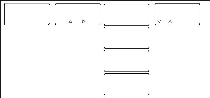
The user interface panel is located on the transfer switch door. Figure 1-1 shows the user interface pushbuttons and LED indicators.
|
|
|
|
|
|
|
|
1 |
|
|
|
|
|
|
|
2 |
|||||||
|
3 |
4 |
|||||
|
|
|
|
|
|
|
|
|
|
|
|
|
|
|
5
9
6
7
GM85884
8
1. |
Source N Available LED |
4. |
Source E Available LED |
6. |
System Alert LED |
8. |
Pushbuttons (4) |
2. |
Source N Position LED |
5. |
USB port for SiteTecht |
7. |
Not in Auto LED |
9. |
Display |
3. |
Source E Position LED |
|
connection |
|
|
|
|
Figure 1-1 User Interface Panel
TP-6883 4/21 |
Section 1 Operation 11 |

1.3.1Display
The four-line display indicates transfer switch status and setup, including the following:
D System status
D Faults and warnings D Active time delays D Source voltages
D Source frequency (Hz) D Current (amps)
D Source setup information D Time and date
D Time and date of next scheduled exercise
The display also identifies the pushbutton functions, which can change from menu-to-menu.
1.3.2Display Contrast
To adjust the display contrast, press and hold the second button until two rows of asterisks (*) appear. Then press the up arrow button to increase the contrast or the down arrow button to decrease the contrast. The display will return to the main menu after a few seconds if no buttons are pressed.
1.3.3Pushbuttons
The user interface panel has four pushbuttons below the display. Pushbutton functions are shown above each button in the last line of the display and can change from menu-to-menu. The pushbutton functions are defined in Figure 1-2.
Note: The current can be set to zero (0) by pressing the first and last pushbuttons together. See section 4.16 for instructions.
BDown arrow (closed). Step down to the next menu or scroll through a list.
YUp arrow (closed). Step back to the previous menu.
"Right arrow (closed). Move to the next submenu.
|
Up arrow (open). Increases the selected |
|
numerical value. |
|
Down arrow (open). Decreases the selected |
|
numerical value. |
|
Right arrow (open). Steps to the next digit in a |
|
selected numerical value. |
Back |
Steps back to the previous menu or submenu. |
End |
Ends the current time delay. |
Delay |
|
End |
Ends an active test sequence. See |
Test |
Section 2.2.3. |
OK |
Enters the displayed numerical value |
|
(password or setting). |
Main |
Returns to the main menu. |
Next |
Steps to the next parameter in an item with |
|
multiple settings (for example, in Exerciser |
|
Setup). |
Reset |
Reset the fault condition shown on the display, |
|
or reset an accessory module after connection. |
Save |
Saves settings shown on the display. |
Set |
From the main menu, moves to the first |
|
setup menu. |
Start |
From the Test menu, starts the test sequence. |
Test |
From the main menu, moves to the test |
|
sequence menus. See Section 1.7. |
View |
From the main menu, moves to the first |
|
view menu. |
Figure 1-2 Pushbutton Functions
12 Section 1 Operation |
TP-6883 4/21 |
1.3.4LED Indicators
LEDs on the user interface indicate contactor position, source availability, faults, and other conditions. The table in Figure 1-3 describes the functions of the LED indicators.
See Section 1.10 for more information about warnings and faults.
Some programmable inputs will trigger the LEDs to light or flash. See Section 4.9.
LED Indicator |
Condition |
|
|
Source N Available, |
Source N is available. |
Green |
|
|
|
Source E Available, Red |
Source E is available. |
|
|
Position A, Green |
Contactor is in Normal position. |
|
|
Position B, Red |
Contactor is in Emergency position. |
|
|
System Alert, Red |
Fault. Identify and correct the cause |
|
of the fault condition, then reset faults |
|
at the controller. See Section 1.10. |
|
|
|
Input active: Low Battery Voltage or |
|
Remote Common Alarm. See |
|
Section 4.9. |
Not in Auto, Red |
ATS is not set for automatic |
|
operation or a load shed (forced |
|
transfer to OFF) sequence is active. |
|
|
|
Flashes for manual transfer waiting. |
|
|
|
Input active: Inhibit Transfer, Forced |
|
Transfer to OFF. See Section 4.9. |
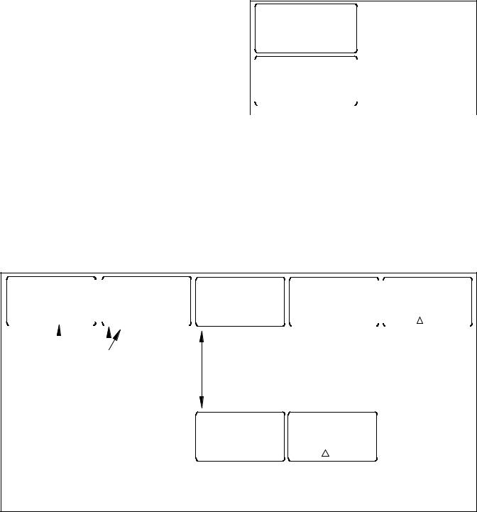
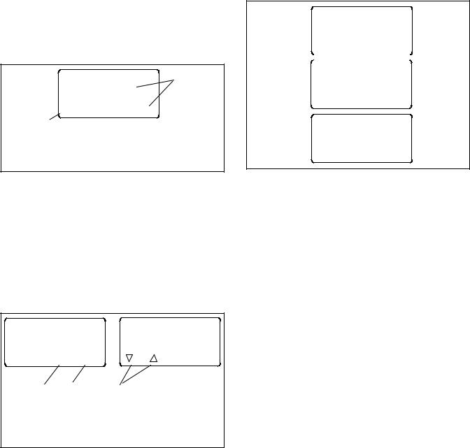
1.3.5Lamp Test
To test the LEDs on the controller’s user interface, go to the Main menu. Press the down arrow button once, then press the Lamp Test button and verify that the LCD menu and all 6 LEDs on the user interface illuminate. See Figure 1-4.
System Ready
LD Exer 12/14 @ 16:00
Norm 480V Emer 480V Press the down arrow button.
B View Set Test
|
|
Norm AB |
BC |
AC |
|
||
|
|
##Hz ###V |
###V ###V |
Press and hold the |
|||
|
|
|
|
Lamp |
|
|
Lamp Test button. |
|
|
|
|
|
|
|
|
|
|
B |
Y |
Test |
Main |
|
|
|
|
|
|||||
|
|
|
|
|
|
|
|
Figure 1-4 |
Lamp Test |
||||||
1.3.6Examples
Figure 1-5 illustrates navigation through the menus.
Figure 1-6 illustrates how to use the pushbuttons to step through menus and change settings. This example shows setting the time.
Figure 1-3 User Interface LED Indicators
Set Common Alarms |
|
|
|
Set Common Alarms |
|||||
|
|
|
|
|
|
|
|
Alarm Group 1 |
|
B |
Y |
" Main |
|
|
B Y |
" Back |
|||
|
|
|
|
|
|
|
|
|
|
|
|
|
|||||||
|
|
|
|
||||||
Press the right arrow |
Press the up and down |
||||||||
button to enter the |
arrow buttons to step |
||||||||
Set Common Alarms |
between alarm groups 1 |
||||||||
menu. |
|
|
|
|
and 2. |
|
|||
Press the right arrow to modify settings in the displayed group.
Modify Alarm
B Y " Back
Press the up and down arrow buttons to select Modify Alarm or Remove All Alarms
Remove All Alarms
B Y " Back
Alarm Description |
|
|
Alarm Description |
|||
Common |
Audible |
|
|
Common Y |
Audible N |
|
|
|
|
|
|
||
B Y |
" Back |
|
|
Back |
Save |
|
|
|
|||||
|
|
|
|
|
|
|
Press the up and down arrow buttons to step through the alarm descriptions. Then press the right arrow to change the common and audible assignments for that function.
Remove All Alarms
Yes/No
Press the up arrow button to step through all combinations of yes and no for common and audible.
Press Save to save the common and audible alarm settings.
Back Save
Press the up arrow button to toggle yes or no. If Yes is displayed, pressing Save will remove all alarms from the selected group (1 or 2).
Pressing Back exits without executing the Remove command.
Figure 1-5 Example: Set Common Alarms
TP-6883 4/21 |
Section 1 Operation 13 |

1 |
|
|
|
|
|
|
|
System OK |
|
|
|
|
|
|
||||||
|
|
|
|
|
|
|
|
|
|
|||||||||||
|
|
|
|
|
LD Exer ##/## @ ##:## |
|
|
|||||||||||||
|
|
|
|
|
|
|||||||||||||||
|
|
|
|
|
Norm ###V Emer |
###V |
|
|
||||||||||||
|
|
|
|
|
B |
|
View Set |
Test |
|
|
||||||||||
|
|
|
|
|
|
|
|
|
|
|
|
|
|
|
|
|
|
|
|
|
|
|
|
|
|
|
|
|
|
|
|
|
|
|
|
|
|
|
|
|
|
|
|
|
|
|
|
|
|
|
|
|
|
|
|
|
|
|
|
|
|
|
|
|
|
|
|
|
|
|
|
|
|
|
|
|
|
|
|
|
|
|
|
|
|
|
|
|
|
|
|
|
|
|
|
|
|
|
|
|
|
|
|
|
|
|
|
|
|
|
|
|
|
|
|
|
|
|
|
|
|
|
|
|
|
Press the SET button.
2 |
Enter Password |
|
Time to Enter #:## |
|
? ? ? ? |
|
OK |
Press the open UP arrow button to increase the first digit of the password from 0 through 9.
Note: The default password is 0000.
3 |
Enter Password |
|
Time to Enter #:## |
|
|
|
0 ? ? ? |
OK
Press the open RIGHT arrow button to move to the next digit. Repeat Steps 2 and 3 until the correct password is displayed.
4 |
Enter Password |
|
Time to Enter #:## |
|
|
|
0 0 0 0 |
OK
Press OK to enter the password.
5 |
|
|
|
|
|
|
Set Time/Date |
|||||||||
|
|
|
|
|
|
|
|
|
|
|
|
|
|
|
|
|
|
|
|
B Y " Main |
|||||||||||||
|
|
|
|
|
|
|
|
|
|
|
|
|
|
|
|
|
|
|
|
|
|
|
|
|
|
|
|
|
|
|
|
|
|
|
|
|
|
|
|
|
|
|
|
|
|
|
|
|
|
|
|
|
|
|
|
|
|
|
|
|
|
|
|
|
|
|
|
|
|
|
|
|
|
|
|
|
|
|
|
|
|
|
|
|
|
|
|
|
|
|
|
|
|
|
|
|
|
|
|
|
|
Press the right arrow button to enter the Set Time/Date submenu.
6
Set Time
B Y " Back
Press the right arrow button to enter the Set Time submenu.
7
Set Time ##:##
Back Save
Press the open up arrow button to increase the first digit. (Use 00:00 to 23:59 for time.)
8
Set Time 1#:##
Back Save
Press the open right arrow button to step to the next digit. Repeat steps 7 and 8 until the correct time is displayed.
9
Set Time 14:37
Back Save
Press Save.
Figure 1-6 Example: Setting the Time
14 Section 1 Operation |
TP-6883 4/21 |

1.4Main Menu
The main menu appears at system startup and displays the following information (see Figure 1-7):
D System Status (see Figure 1-8)
DDate and time of the next scheduled exercise run (if programmed)
D Measured source voltages
D Pushbutton functions
Pressing the down arrow button steps to the normal operation menus shown in Section 1.6. Step through these menus to check the measured frequency, line voltages, current (if the current sensing accessory is installed), and other system information.
Some parameters will appear only under certain conditions. For example:
DIf no exercise runs are scheduled, the second line of the main menu is blank.
DThe Daylight Saving Time settings are displayed only if DST is enabled.
D Phase rotation and in-phase monitoring are displayed only for three-phase systems.
DSome parameters and time delays appear only for programmed-transition models.
D The menus displayed during a test or exercise sequence will vary depending on the time delay settings.
Pressing the View button steps to the view menus shown in Section 3.3.
Passwords are required to enter the setup and test modes. See Section 1.5 for more information about passwords.
Press the Set button to enter the setup mode. A password is required. See Section 4.2 for system setup menus.
Press the Test button to enter the Test mode. A password is required. See Section 1.7.
The display returns to the main menu after 10 minutes of no activity (no buttons pressed).
|
|
|
|
|
|
|
|
|
|
|
|
1 |
|
|
|||
|
|
|
|
2 |
||||
|
|
|
|
|
|
|
||
|
|
|
|
|
|
|
|
|
|
System Ready |
|
|
|
|
|||
|
|
|
|
|
|
3 |
||
|
LD Exer 12/14 @ 16:00 |
|
|
|
|
|||
Norm 480V Emer 480V |
|
|
|
|
||||
B |
View |
Set |
Test |
|
|
|
|
|
|
|
|
|
|
|
|
|
|
6446
1.System status message
2.Next scheduled exercise, if programmed
3.Source voltages detected
Figure 1-7 Main Menu
System Status Messages
Aux Switch Fault
Aux Switch Open
Exerciser Active
External Battery Low
Fail to Acquire Pref
Fail to Acquire Stby
Fail to Transfer
In Phase Waiting
Inhibit Transfer
Low Battery Voltage
Maint DIP Switch
Module Lost Comm
New Module
Peak Shave Active
Phase Rotation Error
Remote Common Alarm
System Ready
Test Mode Active
Figure 1-8 System Status Messages
TP-6883 4/21 |
Section 1 Operation 15 |
1.5Passwords
Passwords are required to enter the Test and Setup menus. Passwords are 4-digit numbers. See Figure 1-9 for instructions to enter the password using the pushbuttons on the controller’s user interface.
There are two passwords:
Setup Password. The setup password controls access to the system setup menus, which allow changes to system settings, time delays, etc.
For closed-transition models, the setup password is required to initiate a transfer when the programmed transition override function is set to manual. See Section 1.7.3.
Test Password. The test password controls access to the test sequence menus. The test password is required to initiate a loaded, unloaded, or auto-loaded test, and also to initiate a sync check test on closed-transition models.
If the correct password is not entered within 30 seconds, the display returns to the main menu.
The factory default password is 0000. Change the password to allow only authorized personnel to start and end tests or change settings.
1.5.1Changing Passwords
Use the Passwords Setup Menu to change passwords. See Section 4.14.
1.5.2Test Password Reset and Disable
The test password can be reset to the default value or disabled. Use the Setup MenuReset Data menu. See Figure 1-26.
Note: Disable the test password only during service unless the transfer switch is located in a secure location.
Disabling the test password allows any user to initiate a test sequence from the controller’s user interface without entering a password. Initiating a test starts the generator set and, if a loaded test is selected, transfers the load.
Note: The factory default password is 0000.
Enter Password Time to Enter #:## > ? ? ? ? <
OK
Press the open up arrow button to increase the first digit of the password from 0 to 9.
Enter Password Time to Enter #:## > 0 ? ? ? <
OK
Press the open right arrow button to step to the next digit. Repeat for all four digits.
Enter Password Time to Enter #:## > 0 0 0 0 <
OK
Press the OK button to enter the password.
Incorrect Password
If the wrong password is entered, the Incorrect Password message appears. Check the password and try again.
Figure 1-9 Entering a Password
16 Section 1 Operation |
TP-6883 4/21 |
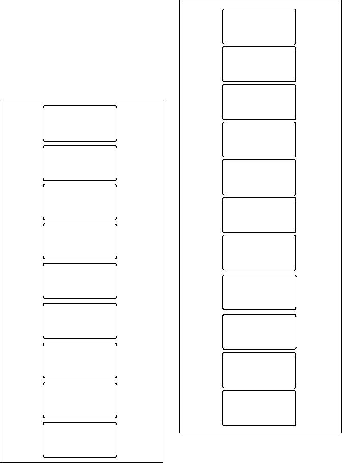
1.6Normal Operation Menus
During normal transfer switch operation, the screens |
|
System Ready |
|
||||||
LD Exer 12/14 @ 16:00 |
|||||||||
shown in Figure 1-10 or Figure 1-11 are displayed. Use |
Norm 480V Emer 480V |
||||||||
the up and down arrow buttons to view the system status |
B |
View |
Set |
Test |
|||||
information as shown. Press Main to return to the main |
|||||||||
|
|
|
|
||||||
menu from any screen. |
|
|
|
Norm |
AB |
BC |
AC |
||
The Sequence of Operation descriptions in Sections 2.2 |
##Hz |
###V |
###V |
###V |
|||||
|
|
Lamp |
|
||||||
through 2.4 describe |
the |
transfer switch normal |
B |
Y |
Test |
Main |
|||
operation for standard, programmed, and closed |
|
|
|
|
|||||
transition models. |
|
|
|
|
Norm |
AN |
BN |
CN |
|
|
|
|
|
|
##Hz |
###V |
###V |
###V |
|
|
System Ready |
B |
Y |
|
Main |
||||
LD Exer 12/14 @ 16:00 |
|
||||||||
|
|
|
|
||||||
Norm 480V Emer 480V |
Emer |
AB |
BC |
AC |
|||||
|
View |
Set |
Test |
||||||
B |
##Hz |
###V |
###V |
###V |
|||||
Norm |
L1 |
L2 |
B |
Y |
|
Main |
|||
##Hz |
###V |
###V |
|
|
|
|
|||
|
|
Lamp |
|
Emer |
AN |
BN |
CN |
||
B |
Y |
Test |
Main |
##Hz |
###V |
###V |
###V |
||
Emer |
L1 |
L2 |
B |
Y |
|
Main |
|||
|
|
|
|
||||||
##Hz |
###V |
###V |
Amps |
LA |
LB |
LC |
|||
|
|
|
|
|
|||||
B |
Y |
|
|
Main |
|
#### |
#### |
#### |
|
|
|
|
|
|
|
||||
Amps |
L1 |
L2 |
B |
Y |
|
Main |
|||
|
|
|
|
||||||
|
|
#### |
#### |
|
Time/Date |
|
|||
|
|
|
|
|
|
|
|||
B |
Y |
|
|
Main |
09:10 DST 01/13/06 |
||||
|
|
|
|
|
|
||||
|
Time/Date |
|
B |
Y |
|
Main |
|||
|
|
|
|
|
|
||||
|
09:10 DST 01/13/06 |
Daylight Saving Time |
|||||||
|
|
|
|
|
|||||
B |
Y |
|
|
Main |
Clock Ahead 1 Hour |
||||
|
|
|
Sun |
03/12/06 |
|||||
|
|
|
|
|
|
||||
|
|
|
|
|
B |
Y |
|
Main |
|
|
Daylight Saving Time |
|
|
|
|
||||
|
Clock Ahead 1 Hour |
Daylight Saving Time |
|||||||
|
Sun |
03/12/06 |
|||||||
|
Clock Back 1 Hour |
||||||||
B |
Y |
|
|
Main |
|||||
|
|
|
Sun |
11/05/06 |
|||||
|
|
|
|
|
|
||||
|
|
|
|
|
B |
Y |
|
Main |
|
|
Daylight Saving Time |
|
|
|
|
||||
|
Clock Back 1 Hour |
Normal Preferred |
|||||||
|
Sun |
11/05/06 |
Util-Gen Operation |
||||||
B |
Y |
|
|
Main |
No Commit Transfer |
||||
|
Normal Preferred |
B |
Y |
|
Main |
||||
|
|
|
|
|
|||||
|
Util-Gen Operation |
|
Standard Transition |
||||||
|
No Commit Transfer |
Phase Rotation ABC |
|||||||
B |
Y |
|
|
Main |
|
In Phase Enabled |
|||
|
|
|
|
|
|
||||
|
|
|
|
|
B |
Y |
|
Main |
|
|
Standard Transition |
|
|
|
|
||||
|
|
|
|
|
Figure 1-11 Three-Phase Operation |
||||
B |
Y |
|
|
Main |
|
|
|
|
|
Figure 1-10 Single-Phase Operation
TP-6883 4/21 |
Section 1 Operation 17 |
1.7System Test
Use the system test feature to:
D Start and run the generator set.
DSimulate a preferred source failure, resulting in a transfer to the standby source.
D Check source synchronization (closed-transition models only).
See Figure 1-12 for the test sequence menus. From the main menu, press the Test button and then enter the password. The password ensures that only authorized personnel can start a test.
Press the down arrow button to navigate to the desired test sequence. Press the Start button to start the test.
Figure 1-13 shows the menus displayed during the test run. Menus are dependent on the system settings and
time delays. See Figure 1-16 for Sync Check menus for closed-transition models.
Press the End Test designated pushbutton to end the test. Time delays will execute as programmed when the test is ended. Press the End Delay button to end the currently displayed time delay, if desired.
To check the source voltage and frequency while a test is running, press the Main button. Press the Test button to return to the test sequence menus.
If the emergency source is lost during a system test, the fail to acquire standby signal is indicated immediately, and the test is terminated. If the contactor is in the standby position, it transfers immediately to the preferred position.
See Section 4.9.3 for additional information about the remote test input.
|
System Ready |
|
|
|
|
Enter Password |
|
LD Exer ##/## @ ##:## |
|
|
Time to Enter #:## |
||
|
Norm ###V Emer ###V |
|
> ? ? ? ? < |
|||
B |
View Set |
Test |
|
|
OK |
|
|
|
|
|
|
|
|
Press the Test button to enter the
Test mode. A password is required.
|
Type of Test |
|
Auto Load Test |
|
|
Auto Load |
|
Enter Time |
|
|
Time :## min |
|
Time ?? min |
|
B |
Main |
" |
Start |
Back OK |
|
Type of Test |
|
|
|
|
|
Loaded |
|
|
B |
Main |
|
Start |
|
|
Type of Test |
|
|
|
|
Unloaded |
|
|
|
B |
Main |
|
Start |
|
|
Type of Test |
|
|
|
|
Sync Check |
|
|
|
B |
Main |
|
Start |
|
Figure 1-12 Test Selection Menus
18 Section 1 Operation |
TP-6883 4/21 |

Engine Start in ##:## Norm ###V Emer ###V
|
End |
End |
Main |
Delay |
Test |
|
|
|
LD# Disc in ##:## Norm ###V Emer ###V
|
End |
End |
Main |
Delay |
Test |
|
|
|
|
|
|
Xfr to Off in ##:## Norm ###V Emer ###V
|
End |
End |
Main |
Delay |
Test |
|
|
|
Xfr to Emer in ##:## Norm ###V Emer ###V
|
End |
End |
Main |
Delay |
Test |
|
|
|
Add LD# in ##:## Norm ###V Emer ###V
|
End |
End |
Main |
Delay |
Test |
|
|
|
|
|
|
System on Test Norm ###V Emer ###V
|
End |
End |
Main |
Delay |
Test |
 LD# Disc in ##:## Norm ###V Emer ###V
|
End |
End |
Main |
Delay |
Test |
|
|
|
|
|
|
Xfr to Off in ##:## Norm ###V Emer ###V
|
End |
End |
Main |
Delay |
Test |
Xfr to Norm in ##:## Norm ###V Emer ###V
|
End |
End |
Main |
Delay |
Test |
Add LD# in ##:## Norm ###V Emer ###V
|
End |
End |
Main |
Delay |
Test |
Eng Cooldown ##:## Norm ###V Emer ###V
|
End |
End |
Main |
Delay |
Test |
Appears if load control time delays are set
Programmed-transition models only
Appears if load control time delays are set
Appears if load control time delays are set
Programmed-transition models only
Appears if load control time delays are set
Note: See Figure 1-16 for Sync Check menus.
Figure 1-13 Test Sequence Menus
1.7.1Unloaded System Test
When an unloaded test is initiated, the controller immediately signals the generator to start, without waiting for the engine start time delay to expire. The contactor does not change position during an unloaded test, but if the normal source should fail, the contactor will transfer to the emergency source.
The unloaded test feature is available only with the Util-Genset and Genset-Genset modes of operation.
The load bank control output is active during an unloaded exercise or unloaded system test. If the contactor transfers to the standby position during the test, the load bank control is deactivated. (The standby source supplies power to the load.)
1.7.2Loaded System Test
A loaded test simulates a preferred source failure, except that the engine start time delay is bypassed. The generator set is signaled to start immediately upon test activation. Load control signals are issued prior to transfer with their associated time delays. Since the loaded test transfer will be between two live sources, the in-phase monitor or closed transition feature will be activated if it is enabled. If the preferred source is lost during a loaded test with the contactor in the standby position, the test will continue to be active, even on restoration of preferred. If the standby source is lost and the preferred source is available, the test will be terminated, and the transfer switch will immediately transfer to the preferred source position, bypassing all time delays except the off-position requirements in a programmed-transition system.
When a loaded test is terminated normally, the retransfer sequence operates as though the preferred source has been restored after a failure. All time delays are executed and an in-phase transfer will occur if enabled. The loaded test feature is available with the Util-Genset, Util-Util and Genset-Genset modes of operation.
1.7.3Closed-Transition Loaded Test
When a loaded test is initiated on a closed-transition model, the generator set is signaled to start and the controller monitors the sources for synchronization. The load is transferred when the sources are synchronized.
TP-6883 4/21 |
Section 1 Operation 19 |
If the sources do not sync before the Fail to Sync time delay expires, the programmed-transition override function operates.
D If the override function is set to Automatic, a programmed-transition transfer will occur when the Fail to Sync time delay expires. The contactor stops in the OFF position for the length of the off-to standby time delay before proceeding to transfer to the standby source.
DIf the override function is set to manual, the user can either initiate a programmed-transition type transfer (setup password required) or cancel the test sequence. See Figure 1-14. If neither action is taken, the controller will continue to check for synchronization and transfer if the sources synchronize.
See Section 4.11.3 for instructions to set the programmed-transition override function.
Manual Transfer |
1 |
Password: |
|
Cancel 
 OK
OK
2
1.Use arrow buttons to enter the setup password and click OK to initiate a manual programmed-transition transfer. OR
2.Press the Cancel button to cancel the test.
Figure 1-14 Manual Transfer Menu for Programmed-Transition Override
1.7.4Auto-Loaded System Test
The auto-loaded test feature is a timed, loaded test. The auto-loaded time delay determines how long after the transfer to standby to terminate the test and transfer back to the preferred source. The time is defaulted to 30 minutes and can be adjusted from 1 minute to 60 minutes. See Figure 1-15.
Type of Test |
Auto Loaded Test |
||
Auto Loaded |
|||
Enter Time |
|||
Time :## min |
|||
Time: ?? min |
|||
|
|
||
B Main " |
Start |
Back OK |
|
1 |
3 |
2 |
|
1.Press right arrow button to go to the Enter Time menu.
2.Use the open arrow buttons to enter the duration time for the test. Then press OK.
3.Press Start to start the test.
Figure 1-15 Auto Loaded Test Menus
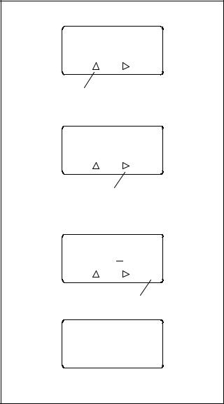
1.7.5Sync Check (closed-transition)
The Sync Check allows a test of the synchronization of two available sources without initiating a transfer. Navigate to the Type of Test, Sync Check menu and press the Start button to begin the test. The controller displays Syncing during the test, and the phase angle difference is shown between two arrows. For example, > 10 < indicates that the sources are 10 degrees out of phase. The arrows move closer together as the sources approach synchronization. When the sources synchronize, the controller indicates Synced and continues to monitor the source synchronization. The load is not transferred. See Figure 1-16. Press the End Test button to end the test.
Type of Test
Sync Check
B Main |
Start |
|
|
|
|
System on Test
Norm ###V Emer ###V
Syncing
End
Main > 102 < Test
System on Test
Norm ###V Emer ###V
Synced
End
Main >< Test
Figure 1-16 Sync Check Menus
1.8Automatic Operation Test
Note: Close and lock the enclosure door before starting the test procedure.
Preferred Source Selection. The test procedure assumes that Source N is the preferred source. If the ATS is equipped with the alarm board accessory, check the preferred source selection before proceeding with the automatic operation test. To check the preferred source selection, use the down arrow button to step down from the main screen until Normal Preferred or Emergency Preferred is displayed. See Figure 1-10 or Figure 1-11.
Supervised Transfer Switch. If the transfer switch is equipped with a supervised transfer switch, verify that it is set to the Auto position.
Follow the procedure below to start a loaded test. Verify that the ATS starts the generator set and transfers the load to the emergency source, executing all time delays that are set up to operate during a loss of the normal source. End the test and verify that the transfer switch transfers the load back to the normal source and removes the engine start signal, executing all
20 Section 1 Operation |
TP-6883 4/21 |
appropriate programmed time delays. Refer to Section 2.2.3 for a more detailed description of the test sequence of operation.
Load control time delay settings may affect the operation sequences.
Note: If the standby source fails during a loaded test, the ATS will immediately attempt to transfer to the preferred source.
Automatic Operation Test Procedure
1.Check the controller LED indicators to verify that the Position N and Source N Available indicators are lit.
2.Verify that the generator set master switch is in the AUTO position.
3.Refer to Figure 1-17. From the main screen, press the Test button. Enter the test password when prompted and press OK.
4.Press the down arrow button to display Type of Test Loaded.
5.Press the Start button.
6.Verify that the generator set starts and the Source E Available LED lights.
7.Verify that the switch transfers the load to Source E. Observe the controller LEDs and display as the time delays execute and the load is transferred.
a.Standard-Transition Models: After the preferred-to-standby transfer time delay, verify that the Position N LED turns off and the Position E LED lights, indicating that the switch has transferred the load to Source E.
b.Programmed-Transition Models: After the preferred-to-off time delay, verify that the Position N LED turns off. After the off-to-standby time delay, check that the Position E LED lights, indicating that the switch has transferred the load to Source E.
c.Closed-Transition Models: See Section 1.7.3. After the preferred-to-standby time delay, the controller monitors the sources for synchronization. When the sources are in sync, the ATS transfers the load to Source E and the Position E LED lights. Both sources will be connected for less than 100 milliseconds before Source N is disconnected and the Position N LED turns off.
If the sources do not synchronize before the fail to sync time delay expires, operation depends on the programmed transition override setting. If automatic override is enabled, the ATS will transfer the load using a programmedtransition transfer. If automatic override is not enabled, the ATS will continue to monitor the source synchronization and transfer when/if the sources synchronize. The operator can initiate a programmed-transition transfer (password required) or cancel the transfer.
8.Press the End Test button.
9.Verify that the switch transfers the load back to Source N.
a.Standard-Transition Models: After the standby-to-preferred time delay, verify that the Position E LED goes out and the Position N LED lights, indicating that the switch has transferred the load to Source N.
b.Programmed-Transition Models: After the standby-to-off time delay, verify that the Position E LED goes out. After the off-to- preferred time delay, check that the Position N LED lights, indicating that the switch has transferred the load to Source N.
c.Closed-Transition Models: See Section 1.7.3. After the standby-to-preferred time delay, the controller monitors the sources for synchronization. When the sources are in sync, the ATS transfers the load to Source N and the Position N LED lights. Both sources will be connected for less than 100 milliseconds before Source E is disconnected and the Position E LED turns off.
If the sources do not synchronize before the fail to sync time delay expires, operation depends on the programmed transition override setting. If automatic override is enabled, the ATS will transfer the load using a programmedtransition transfer. If automatic override is not enabled, the ATS will continue to monitor the source synchronization and transfer when/if the sources synchronize. The operator can initiate a programmed-transition transfer (password required).
10.After the engine cooldown time delay expires, the engine start signal is removed. Verify that the generator set stops.
Note: The generator set may have an engine cooldown time delay that causes the generator set engine to run after the transfer switch engine start signal is removed.
TP-6883 4/21 |
Section 1 Operation 21 |
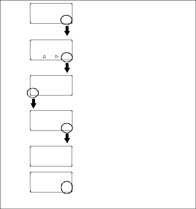
System OK
LD Exer ##/## @ ##:## Norm ###V Emer ###V
B View Set Test
Enter Password Time to Enter #:## > ? ? ? ? <
OK
Type of Test
Auto Load
Time :## min
B Main " Start
Type of Test
Loaded
B Main |
Start |
Engine Start in ##:## Norm ###V Emer ###V
End End
Delay Test
System on Test Norm ###V Emer ###V
|
End |
Main |
Test |
On the main screen, press the Test button.
Use the open arrow buttons to enter the Test password. See Section 1.5 for instructions. Then press the OK button.
Press the down arrow button to step to the loaded test screen.
Press the Start button to initiate the test sequence.
Additional test sequence screens may appear, depending on the system settings.
Press the Main button to return to the main screen during the test, if desired. From the main screen, press Test to return to the test screen.
Press the End Test button to end the test.
Figure 1-17 Starting and Stopping the Automatic Operation Test
22 Section 1 Operation |
TP-6883 4/21 |
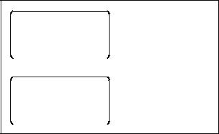
1.9Exercise
Schedule exercise runs through the Set Exercise menus. See Section 4.4. To run the generator set at a time other than a scheduled exercise sequence, use the Test function. See Section 1.7 for instructions.
When a scheduled exercise is running, the menus shown in Figure 1-18 appear. Press Main to return to the main menu, if desired. Press the End button to end the exercise sequence before the scheduled stop time, if necessary.
If a system test or peak shave is active when the exercise is scheduled to occur, the exercise is skipped. A preferred-source failure during an exerciser period causes the exercise to be terminated and normal ATS operation to resume.
An exercise event can be temporarily disabled to prevent its execution and then re-enabled later using the enable/disable setting in the Set Exercise menus. See Section 4.4.
1.9.1Unloaded Exercise
An unloaded exercise starts and runs the generator set without transferring the load.
1.9.2Load Bank Control
The load bank control output is active during an unloaded exercise or unloaded system test. If the
contactor transfers to the standby position, the load bank control will be deactivated. (The standby source supplies power to the load.)
1.9.3Loaded Exercise
A loaded exercise starts the generator set and transfers the load from the normal source to the standby source.
On closed-transition models, transfer will occur when the sources are synchronized. If the sources do not sync, press Cancel to end the exercise.
Exerciser Active Fail to Acquire 00:59 Norm ###V Emer ###V
Main |
End |
|
|
Exerciser Active
Time Remaining 00:29 Norm ###V Emer ###V
Main |
End |
|
|
Display during generator set engine start or if engine does not start immediately.
Display during exercise run.
Figure 1-18 Exercise Sequence Menus
TP-6883 4/21 |
Section 1 Operation 23 |
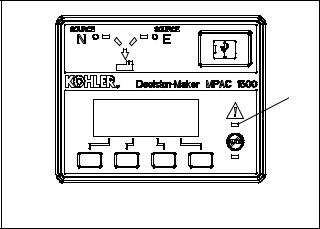
1.10 Warnings and Faults
When a fault exists, the System Alert indicator flashes, a designated output and the common fault output are turned on, and an appropriate message is displayed to indicate the fault. See Figure 1-19 for the location of the System Alert indicator.
1
1. System Alert LED |
GM85888 |
ATS warnings and faults are shown in Figure 1-20. There are three types of warning/fault conditions:
Warning. Warnings automatically reset with a source availability change or a transfer request.
Fault Requiring Manual Reset. Under these conditions, normal ATS operation is halted. Active modes are turned off. If the contactor is in the preferred source position, the engine cooldown time delay executes and the engine start contacts open, allowing the generator set to shut down. See Section 1.10.1 for instructions to reset faults.
Self Resetting Faults. Under these conditions, active modes are turned off. If the contactor is in the preferred source position, the engine cooldown time delay executes and the engine start contacts open, allowing the generator set to shut down. When the fault condition is corrected, the fault is automatically cleared from the controller and normal ATS operation continues.
Figure 1-19 Fault Indication
Condition |
Type |
Description |
|
|
|
|
|
Failure to Acquire Standby Source |
Warning |
The source voltage did not reach the acceptable range within a set |
|
|
|
time (see Time Delays). For example, the standby source generator |
|
Failure to Acquire Preferred Source |
Warning |
||
set did not start. |
|||
|
|
|
|
IPM Synching |
Warning (status) |
The two sources did not come into phase within the Fail to |
|
(In-Phase Monitor Synching) |
|
Synchronize time delay. |
|
|
|
Note: If the sources do come into phase after the time delay |
|
|
|
expires, the warning is automatically cleared and normal ATS |
|
|
|
operation continues. |
|
|
|
|
|
External Battery Low |
Warning |
The voltage of the battery connected to the external battery supply |
|
|
|
module (EBSM) is low. |
|
|
|
|
|
Failure to Transfer |
Warning |
The signal to transfer is sent to the contactor and the main shaft |
|
|
|
auxiliary switch fails to indicate a complete ATS position change. |
|
|
|
The controller will attempt to transfer the unit three times before the |
|
|
|
fault is indicated. |
|
Src N (or Src E) Rotation Err |
Self-Resetting Fault |
The detected phase rotation of one or both sources does not match |
|
|
|
the preselected setting. |
|
|
|
|
|
I/O Module Lost Comm |
Self-Resetting Fault |
An I/O device has stopped communicating or does not have a |
|
|
|
correct address specified. Fault resets if communication is |
|
|
|
reestablished. |
|
Auxiliary Switch Fault |
Manual Reset Fault |
The main shaft auxiliary switches indicate that the ATS is in more |
|
|
|
than one position, or the position changed when no signal was sent |
|
|
|
to initiate the change. |
|
|
|
|
|
Auxiliary Switch Open |
Manual Reset Fault |
The main shaft auxiliary switches indicate that the ATS is in neither |
|
|
|
position (all inputs are open). |
|
|
|
|
|
Source1/Source2 Breaker Trip |
Manual Reset Fault |
The Source1 or Source2 circuit breaker in the service entrance |
|
(service entrance models only) |
|
transfer switch has tripped due to an overcurrent condition. Identify |
|
|
|
and correct the cause of the fault before resetting the controller. |
|
|
|
|
|
Module Status Change |
Manual Reset Fault |
An accessory module has been disconnected OR a new module is |
|
|
|
detected. See Section 1.11.1 to reset. |
|
|
|
|
|
Module Status Conflict |
Manual Reset Fault |
An accessory module has been replaced with a different type of |
|
|
|
module with the same address. See Section 1.11.2 to reset. |
|
|
|
|
|
External Fault |
Self-Resetting Fault |
The external input dedicated to this condition is closed. |
|
Figure 1-20 Warnings and Faults |
|
|
24 Section 1 Operation |
TP-6883 4/21 |
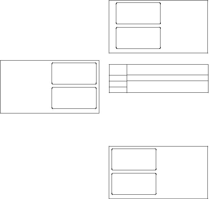
1.10.1 Fault Reset
To clear a fault or warning condition and reset the System Alert LED, go to the Main menu and press the down arrow button to open the Reset menu. See Figure 1-19 and Figure 1-21. Then press the button labeled Reset. A fault reset does not change the controller settings.
See Section 1.11, Accessory Module Faults, for instructions to correct and reset faults related to the I/O modules and other accessory modules.
When a fault message is displayed, press the down arrow (B) button on the Main menu to step to the Reset Fault menu.
Then press the Reset button.
Fault Message
LD Exer ##/## @ ##:## Norm ###V Emer ###V
B View Set Test
Reset
Fault Description
B Y Reset Main
Figure 1-21 Fault Reset
1.11 Accessory Module Faults
Accessory modules are optional equipment.
1.11.1 Module Status Change
Connecting or disconnecting one or more accessory modules can cause the Module Status Change message to be displayed.
Module Connection (new or reconnected module)
Installing or reconnecting one or more accessory modules triggers the Module Status Change message. See Figure 1-22. Press the Reset button to display Reset New Module. Press the Reset button from that menu. The controller recognizes the module type(s). See Figure 1-23.
Navigate to the Set Input/Outputs>Set Aux I/O menu to check that the controller has recognized the connected modules.
See Section 4.9 for instructions to assign programmable inputs and outputs to I/O modules. Go to Section 4.10 for instructions to assign functions to the audible alarm for an Alarm Module.
Module Status Change |
|
|||
Norm ###V Emer ###V |
Press Reset. |
|||
|
||||
Reset |
View |
Set |
Test |
|
|
Reset |
|
|
|
|
New Module |
|
Press Reset. |
|
|
|
|
|
|
B |
Y |
Reset Main |
|
|
Figure 1-22 Menus after Module Connection
Module
Type Description
AOB Switch/Alarm Module (alarm option board) SOB Standard I/O Module (standard option board) POB High-Power I/O Module (power option board)
Figure 1-23 Module Types
Disconnected Module
If one or more accessory modules are disconnected from the controller, the message Module Status Change appears. See Figure 1-24. Pressing the Reset button displays the message Check Module Setup to Clear Fault. Use the following Module Uninstall Procedure to uninstall modules after disconnection.
Module Status Change
Norm ###V Emer ###V |
Press Reset. |
||
|
|||
Reset |
View |
Set Test |
|
Check Module Setup |
Press Main and follow |
||
|
to Clear Fault |
Module Uninstall |
|
|
|
|
Procedure. |
B |
Y |
Reset Main |
|
Figure 1-24 Menus after Module Disconnection
TP-6883 4/21 |
Section 1 Operation 25 |
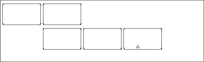
Module Uninstall Procedure
1.Press Main to return to the main menu.
2.Press Set to enter setup mode.
3.Enter the setup password.
4.Press the down arrow to step to the Set Inputs/ Outputs menu.
5.Navigate to the Set Auxiliary I/O menu. See Figure 1-25. Press the right arrow button to see the status of module 1. Press the down arrow to step to the next module, if necessary, until the menu shows Status: Lost.
6.Press the right arrow button to move to the Uninstall Module menu. Verify that the menu says Uninstall Module Yes. (Press the open arrow button to toggle no/yes, if necessary.)
7.When Yes is displayed, press Save to uninstall the module.
8.Repeat the uninstall procedure for additional modules, if necessary.
Other Module Status Change Conditions
A Module Status Change message that cannot be cleared as described in this section may indicate a failure of the controller’s real-time clock. Carefully follow the Module Connection or Module Uninstall procedures to attempt to reset the fault. If the fault cannot be reset, the controller’s logic board may need to be replaced. Contact an authorized distributor/dealer for service.
1.11.2 Module Status Conflict
The message Module Status Conflict appears if one type of module is replaced with another type of module that has the same address. Follow the procedure below to resolve the conflict.
Procedure to Clear a Module Status Conflict
1.Disconnect power to the transfer switch.
2.Disconnect the module.
3.Close the enclosure door and reconnect power to the ATS. The display will show Module Status Change.
4.Press the button labeled Reset. The display will show Check Module Setup to Clear Fault.
5.Follow the procedure in Section 1.11.1 to uninstall the module through the ATS controller keypad.
6.Disconnect power to the ATS.
7.Connect the new module.
8.Close the enclosure door and reconnect power to the ATS. The display will show Module Status Change. See Figure 1-22.
9.Press the button labeled Reset to display Reset New Module. Press the reset button from that menu. The controller will now recognize the new module type.
10.Navigate to the Set Auxiliary I/O menu to check the status and settings for the new module. See Figure 1-25. Press the right arrow button to see the status of module 1. Press the down arrow to step to the next module, if necessary,
|
Set |
Set Inputs/Outputs |
Main Board I/O |
B Y " Main B |
Y |
" Back |
|
|
|
|
Set |
Module 1 |
Module 1 |
|
Auxiliary I/O |
Type POB Addr 1 |
Uninstall Module |
|
|
|
|
Status: Lost |
Yes |
B |
Y |
" Back |
B Y " Back |
Save Back |
 Press the down arrow button to step to the next module, if necessary.
Figure 1-25 Uninstall Module
26 Section 1 Operation |
TP-6883 4/21 |
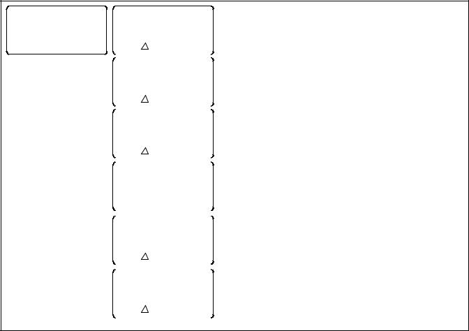
1.12 Reset Data
Be sure to read and understand the information in this section before resetting records or parameters.
Note: Resetting to the default parameters will reset all parameters to a factory default setting.
Use the Reset Data menus to set records or parameters back to factory default settings. See Figure 1-26.
1.Use the black arrow buttons to step to the desired menu.
2.Press the open up arrow button to toggle Yes or No until Yes is displayed.
3.Press Save to reset the records or parameters to the factory defaults. Pressing Back exits the menu without resetting.
1.12.1 Reset Maintenance Records
Reset the maintenance records after transfer switch service to update the last maintenance date and totals since reset that are displayed in the maintenance records menu.
1.12.2 Reset Event History
Resetting the event history clears the events from the event history log. The history lists the 100 most recent transfer switch events, including transfers and DIP switch setting changes as well as faults and alarms.
Reset Data
B Y " Main
Reset
Maintenance Records
|
Yes/No |
|
B |
Save |
Back |
|
|
|
|
|
|
|
Reset |
|
|
Event History |
|
|
Yes/No |
|
B |
Save |
Back |
|
|
|
|
|
|
Reset
Default Parameters
Yes/No
B |
Save |
Back |
|
|
|
|
|
|
|
Reset |
|
|
Exerciser Setup |
|
|
Yes/No |
|
B |
Save |
Back |
|
|
|
|
|
|
|
Reset |
|
|
Test Password |
|
|
Yes/No |
|
B |
Save |
Back |
|
|
|
|
|
|
|
Disable |
|
|
Test Password |
|
|
Yes/No |
|
B |
Save |
Back |
|
|
|
Note: Resetting to the default parameters will reset all parameters, including the system voltage and frequency, to a factory default setting. The transfer switch will not operate correctly if the system voltage and frequency do not match the sources.
Note: Disable the test password only during service unless the transfer switch is installed in a secure location.
Figure 1-26 Reset Data
TP-6883 4/21 |
Section 1 Operation 27 |
1.12.3 Reset Default Parameters
Resetting to the default parameters will reset all parameters, including the system voltage and frequency, to a factory default setting. The default system voltage and frequency settings may not match the settings for your application.
The transfer switch will not operate correctly if the system voltage and frequency do not match the sources. Use the Set Sources menu to set the system voltage and frequency after resetting to the default parameters. See Section 6 for instructions.
Check the system operation to verify the settings after resetting.
1.12.4 Reset and Disable Test Password
Reset the Test password to return the test password to the default, 0000.
Note: Disable the test password only during service unless the transfer switch is installed in a secure location.
Disabling the test password allows any user to initiate a test sequence from the controller’s user interface without entering a password. Initiating a test starts the generator set and, if a loaded test is selected, transfers the load.
28 Section 1 Operation |
TP-6883 4/21 |

Section 2 Sequence of Operation
This section explains the transfer switch sequence of operation during the following events:
D Controller power-up or reset
D Preferred source loss and return
D Test
D Exercise
D Emergency source loss and return
The Sequence of Operation descriptions in Sections 2.2 through 2.4 describe the transfer switch normal operation for standard, programmed, and closed transition models. Operation can be affected by faults such as the normal or emergency contacts failing to open or close when signaled to do so.
2.1Controller Power-up/Reset
Following is an explanation of the sequence of operation for the Decision-Makerr MPAC 1500 ATS Controller when power is initially applied to the controller or a controller reset occurs.
1.Controller self test is executed.
2.System parameters are downloaded from nonvolatile memory.
3.Contactor position and source availability are determined.
4.If neither source is acceptable, the contactor does not change position.
5.If both sources are available, the controller immediately transfers the contactor to the preferred source.
6.If only one source is available, the controller immediately transfers the contactor to that source, executing only the off-position and load control time delays.
If the available source is the preferred source, and the contactor is in the standby position, the contactor transfers to preferred, the engine cooldown time delay runs, and then the engine start contacts open.
If the available source is the preferred source and the contactor is already in the preferred position, the engine start contacts open immediately, bypassing the engine cooldown time delay.
TP-6883 4/21 |
Section 2 Sequence of Operation |
29 |
2.2Sequence of Operation, Standard Transition Models
Operation can be affected by faults such as the normal or emergency contacts failing to open or close when signaled to do so.
2.2.1Preferred Source Loss and Return, Standard Transition
Following is an explanation of the transfer switch sequence of operation when Preferred Source failure is detected.
Preferred Source Fails
1.Load control contacts open.
2.Engine start time delay expires.
3.The generator is signaled to start.
4.The generator starts and the standby source becomes available.
5.Preferred-to-standby time delay expires.
6.Contactor transfers to standby.
7.Post-transfer load control sequences run.
8.Load control contacts close.
Preferred Source Returns
1.Standby-to-preferred and pre-transfer load control time delays expire.
2.Load control contacts open.
3.Contactor transfers to preferred source.
4.Post-transfer load control sequences and engine cooldown time delay expire.
5.Load control contacts close.
6.The engine start contacts open, signaling the generator to stop.
2.2.2Exerciser Operation, Standard Transition
Unloaded Exercise Sequence Starts
1.Exerciser timer begins.
2.The generator is signaled to start.
3.The generator starts and the standby source becomes available.
4.The load bank control is activated.
Unloaded Exercise Sequence Ends
1.The load bank control is deactivated.
2.Engine cooldown time delay expires.
3.The engine start contacts open, signaling the generator to stop.
Loaded Exercise Sequence Starts
1.Exerciser timer begins.
2.The generator is signaled to start.
3.The generator starts and the standby source becomes available.
4.Preferred-to-standby time delay and pre-transfer load control sequences run.
5.Load control contacts open.
6.Contactor transfers to standby.
7.Post-transfer load control sequences run.
8.Load control contacts close.
Emergency Source Fails (Normal Source is available)
1.Exerciser is deactivated.
2.Load control contacts open.
3.Contactor immediately transfers to preferred.
4.Immediate failure to acquire standby alarm.
5.Post-transfer load control sequences and engine cooldown time delay expire.
6.Load control contacts close.
7.Engine start contacts open.
30 |
Section 2 Sequence of Operation |
TP-6883 4/21 |
 Loading...