


96M1119
Instruction
Manual
Ultra High Accuracy Laser Displacement Meter
LC-2400 Series

Safety Precautions
This manual describes how to install the LC-2400 Series as well as its operating procedures and precautions. Please read this manual carefully to get the best from your LC-2400 Series.
Symbols
The following symbols alert you to important messages. Be sure to read these messages carefully.

 WARNING

 CAUTION
Note
Failure to follow instructions may lead to injury. (electric shock, burn, etc.)
Failure to follow instructions may lead to product damage.
Provides additional information on proper operation.
General Precautions

 CAUTION
•At startup and during operation, be sure to monitor the functions and performance of the LC-2400 series.
•We recommend that you take substantial safety measures to avoid any damage in the event a problem occurs.
•Do not open or modify the LC-2400 series or use it in any way other than described in the specifications.
•When the LC-2400 series is used in combination with other instruments, functions and performance may be degraded, depending on operating conditions and the surrounding environment.
•Do not use the LC-2400 series for the purpose of protecting the human body.
Turn the power OFF when connecting or disconnecting the sensor head connector, power supply cables, or any of the optional boards. Otherwise, the laser diode or other electronic components may become degraded or damaged.
i

Contents of the Package The LC-2400 series includes the following items. Check that none of the items are missing or damaged.
●Display unit model: LC-D1A/LC-D1W (Qty: 1)
If the control unit was ordered separately, the display unit is not included.
●Control unit model:
LC-C1A / LC-C1W/LC-C2(1)
If the display unit was ordered, the control unit is incorporated in the display unit.
● Sensor head1.
Check that the requested sensor head is included in the contents.
model: LC-2420 |
model: LC-2440 |
LC-2430 |
LC-2450 |
● 3-m connecting cable (1) 1., 2. |
● 2-m power cable (1) |
● Ferrite core |
● Ferrite core |
ESD-SR-25 (TOKIN) for RS-232C |
ZCAT3035-1330 (TDK) for CON- |
cable (2) 3. |
TROL I/O cable (2) 3. |
● Power supply key (2) |
● 24-pin control I/O connector (1) |
● 4-pin laser remote grounding |
● Instruction manual (1) |
plug (1) |
|
Inserting this plug into the LASER |
|
REMOTE connector on the rear panel |
LC–2400 Series |
enables laser emission. (See page 15.) |
|
|
Instruction Manual |
1.Depends on quantity ordered
2.5-m or 10-m cable is also available.
(To use a 5-m or 10-m cable with the LC-2400 series that has been calibrated for a 3-m cable the unit must be recalibrated by KEYENCE. We also offer the LC2400 series configured for 5-m and 10-m cables.)
3.Included with the LC-2400W series.
Note
• The 5-m or 10-m cable is not available for the LC-2400W series.
• The LC-C1W cannot be used seperately from the display unit.
ii

WARRANTIES AND DISCLAIMERS
Sea page 113.
Conventions |
The following symbols are used in this manual: |
|
|
|
Failure to follow instructions may lead to injury. |
|
WARNING |
|
|
(electric shock, burn, etc.) |
|
|
|
|

 CAUTION
Note
Cautions against procedures which may result in malfunctions or measurement errors as well as hazardous operating conditions. Be sure to read this information carefully.
Turn to this page for more detailed information on a given subject.
Read here for more details or for reference information on a given subject. This information can be read as required.
LC-2400 operation keys.
iii

How to Use This Instruction Manual
Chapter Guide
This instruction manual is composed of 9 chapters. An introduction to each chapter is given below:
Users who are using the LC-2400 series for the first time are encouraged to read through the entire instruction manual.
1.LASER SAFETY PRECAUTIONS
This chapter describes the safety precautions for dealing with the laser in the LC-2400 series.
2.SYSTEM CONFIGURATION
This chapter introduces the LC-2400 series measurement system. A "Quick Reference Table" is also included to help you quickly locate the information and procedures that you require.
3.PART NAMES AND FUNCTIONS
This chapter identifies parts used in the LC-2400 series.
4.OPERATING INSTRUCTIONS
This chapter explains in detail how to operate the LC controller. Please read and follow the instructions in this chapter carefully before operating the LC.
5.CONNECTIONS
This chapter explains the procedures for installing a sensor and connecting it to the LC controller.
6.SETTING UP
This chapter explains how to set the parameters quickly and easily for obtaining accurate measurements with the LC-2400 series. Read how to set the parameters in this chapter after checking the system setup against the table given in Chapter 2-4 "Quick Reference Table".
7.MEASUREMENT PROCEDURE
This chapter explains measurement procedures using various targets.
8.EXTERNAL I/O FUNCTIONS
This chapter explains how to communicate with external I/O devices such as a personal computer.
9.APPENDIX
The appendix includes a troubleshooting guide, a glossary, and a description of the expansion I/Os.
iv

TABLE OF CONTENTS
|
CHAPTER 1 |
LASER SAFETY PRECAUTIONS |
1 |
|
|
|
|
|
|
|
|
1-1 |
Classification ................................................................................... |
2 |
|
|
1-2 |
Warning Label ................................................................................. |
2 |
|
|
1-3 |
Label Location ................................................................................ |
3 |
|
|
1-4 |
Safety Consideration ...................................................................... |
3 |
|
|
1-5 Safety Features Provided with the LC-2400 Series ........................ |
4 |
|
|
|
|
|
|
|
CHAPTER 2 |
SYSTEM CONFIGURATION |
5 |
|
|
|
|
|
|
|
|
2-1 |
Basic System Configuration ............................................................ |
6 |
|
|
2-2 |
Expansion System Configuration .................................................... |
7 |
|
|
2-3 Sensor Head Types and Functions ................................................ |
8 |
|
|
|
2-4 |
Quick Reference Table ................................................................... |
9 |
|
|
|
|
|
|
CHAPTER 3 |
PART NAMES AND FUNCTIONS |
11 |
|
|
|
3-1 |
Controller ...................................................................................... |
12 |
|
|
|
Front Panel .............................................................................. |
12 |
|
|
|
Rear Panel ............................................................................... |
14 |
|
|
3-2 |
Sensor Head ................................................................................. |
16 |
|
|
|
|
|
|
CHAPTER 4 |
OPERATING INSTRUCTIONS |
17 |
|
|
|
|
|
|
|
|
4-1 Instructions for Using Controller and Sensor Head ...................... |
18 |
|
|
|
|
After Receiving the LC-2400 Series ........................................ |
18 |
|
|
|
Daily Maintenance Instructions ................................................ |
18 |
|
|
|
Replacing Battery .................................................................... |
19 |
|
|
|
Instructions for Sensor Setup .................................................. |
20 |
|
|
|
Hints on Correct Use ............................................................... |
10 |
|
|
|
|
|
|
CHAPTER 5 |
CONNECTIONS |
21 |
|
|
|
|
|
|
|
|
5-1 Connecting Controller to Sensor Head ......................................... |
22 |
|
|
|
5-2 Connecting Power Supply Cable .................................................. |
22 |
|
|
|
|
Connecting Controller to Sensor Head |
|
|
|
|
When Using the Display Unit ................................................. |
22 |
|
|
|
Connecting the Power Supply Unit |
|
|
|
|
to a Separate Control Unit .................................................... |
23 |
|
|
5-3 |
Grounding Controller .................................................................... |
23 |
|
|
|
Grounding the Controller |
|
|
|
|
When Using the Display Unit ................................................. |
23 |
|
|
|
Grounding the Control Unit ...................................................... |
23 |
|
|
5-4 Installing LC-B3 Board (2CH Sensor Head Board) ....................... |
24 |
|
|
|
5-5 Installing GP-IB or DIGITAL I/O Board ......................................... |
24 |
|
|
|
5-6 Adjusting Sensor Head Position ................................................... |
25 |
|
v

|
CHAPTER 6 |
SETTING UP |
27 |
||
|
|
6-1 |
Basic Operation of Controller ........................................................ |
28 |
|
|
|
6-2 |
Selecting Measurement Mode ...................................................... |
30 |
|
|
|
6-3 |
Calibrating Sensitivity (Gain Selection) ......................................... |
30 |
|
|
|
6-4 |
Selecting the Display/Output Mode .............................................. |
31 |
|
|
|
6-5 |
Correcting Measurement Error (Calibration) ................................. |
32 |
|
|
|
6-6 |
Offset Values ................................................................................ |
35 |
|
|
|
6-7 |
Reducing Variation in Measurement Data |
|
|
|
|
|
(Setting Number of Averaging Measurements) .......................... |
36 |
|
|
|
6-8 |
Reducing the Effect of Target Surface Irregularities |
|
|
|
|
|
(Setting Low-pass Filter Value) ................................................... |
36 |
|
|
|
6-9 |
Setting Range for Light Intensity (INT. LIMIT) .............................. |
37 |
|
|
|
6-10 |
Setting Upper/Lower Limits for Measurements |
|
|
|
|
|
(Setting Tolerance) ..................................................................... |
39 |
|
|
|
6-11 |
Setting Number of Digits Displayed .............................................. |
40 |
|
|
|
6-12 |
Storing and Loading Settings (Programming) ............................... |
41 |
|
|
|
|
|
|
|
|
CHAPTER 7 |
MEASUREMENT PROCEDURE |
43 |
||
|
|
|
|
|
|
|
|
7-1 |
Measuring with One Sensor Head ................................................ |
44 |
|
|
|
7-2 |
Measuring with Two Sensor Heads .............................................. |
45 |
|
|
|
|
|
|
|
|
CHAPTER 8 |
EXTERNAL INPUT/OUTPUT |
49 |
||
|
|
|
|
|
|
|
|
8-1 |
........................................................................RS-232C Interface |
50 |
|
|
|
8-2 |
Control I/O (Standard Equipment on Display Unit) ....................... |
71 |
|
|
|
8-3 |
Analog Voltage Output (Standard Equipment) ............................. |
73 |
|
|
|
8-4 |
Digital I/O (Standard Equipment on Control Unit) ......................... |
74 |
|
|
|
|
|
|
|
|
CHAPTER 9 |
APPENDIX |
|
|
79 |
|
|
|
|
|
|
|
|
9-1 |
Trouble-Shooting Guide ................................................................ |
80 |
|
|
|
9-2 |
Hints on Highly Accurate Measurement ....................................... |
83 |
|
|
|
9-3 |
Specifications ................................................................................ |
84 |
|
|
|
9-4 |
Dimensions ................................................................................... |
85 |
|
|
|
9-5 |
Characteristics .............................................................................. |
87 |
|
|
|
9-6 |
Initial Setting List ........................................................................... |
89 |
|
|
|
9-7 |
Glossary ........................................................................................ |
90 |
|
|
|
9-8 |
Expansion I/O (Optional) .............................................................. |
94 |
|
|
|
9-9 |
Index ........................................................................................... |
111 |
|
|
|
|
|||
|
WARRANTIES AND DISCLAIMERS |
|
113 |
||
|
|
|
|
|
|
vi

CHAPTER 1
LASER SAFETY PRECAUTIONS
1-1 |
Classification ................................................................... |
2 |
1-2 |
Warning Labels ................................................................ |
2 |
1-3 |
Label Location ................................................................. |
3 |
1-4 |
Safety Consideration ....................................................... |
3 |
1-5 Safety Features Provided with the LC-2400 Series ......... |
4 |
|

1-1 Classification
1-2 Warning Labels
1-1 Classification
The LC-2400 series employs a visible semiconductor laser as its light source classified as follows:
|
|
Model |
LC-2420 |
LC-2430 |
LC-2440 |
LC-2450 |
||
|
||||||||
|
|
|
|
|
|
|
|
|
|
|
Class |
FDA (CDRH) |
|
Class II |
|
||
|
|
|
|
|
|
|
|
|
|
|
|
|
IEC/EN 60825-1:1993+ |
|
Class 2 |
|
|
|
|
|
|
A2: 2001 |
|
|
||
|
|
|
|
|
|
|
|
|
|
|
|
|
|
|
|
|
|
|
|
|
|
DIN EN 60825-1 2001 |
|
Klasse 2 |
|
|
|
|
|
|
|
|
|
|
|
|
|
|
|
|
|
|
|
|
1-2 Warning Labels
Warning Labels |
1) Warning labels |
||
|
FDA Class II |
||
|
|
|
|
|
|
CAUTION |
|
|
|
LASER RADIATION- |
|
|
|
DO NOT STARE INTO BEAM |
|
|
|
SEMICONDUCTOR LASER 670nm |
|
|
|
MAXIMUM OUTPUT |
1.9mW |
|
|
(AVERAGE OUT PUT |
950 W) |
|
|
PULSE DURATION |
10 SEC |
CLASS II LASER PRODUCT
IEC Class 2
AVOID EXPOSURE |
AVOID EXPOSURE |
LASER RADIATION |
LASER RADIATION |
IS EMITTED FROM |
IS EMITTED FROM |
THIS APERTURE. |
THIS APERTURE. |
AVOID EXPOSURE
LASER RADIATION
IS EMITTED FROM
THIS APERTURE.
CAUTION
LASER RADIATION-
DO NOT STARE INTO BEAM SEMICONDUCTOR LASER 670nm
MAXIMUM OUTPUT |
1.9mW |
(AVERAGE OUT PUT |
950 W) |
PULSE DURATION |
10 SEC |
CLASS II LASER PRODUCT
IEC (French) Classe 2
DIN
Klasse 2
2 |
CHAPTER 1 Laser Safety Precautions |
|

1-3 Label Locations
1-4 Safety Consideration
1-3 Label Location
FDA
• LC–2420/2430


 LC–2420
CAUTION
LASER RADIATION- |
|
AVOID EXPOSURE |
|
LASER RADIATION |
|
DO NOT STARE INTO BEAM |
||
SEMICONDUCTOR LASER 670nm |
IS EMITTED FROM |
|
MAXIMUM OUTPUT |
1.9mW |
THIS APERTURE. |
(AVERAGE OUT PUT |
950 W) |
|
PULSE DURATION |
10 SEC |
|
CLASS II LASER PRODUCT
FDA Warning labels are attached to the sensor head as shown below. The IEC/DIN Warning labels are packaged with the LC-2400 Series. Affix the Warning labels on the sensor head as shown below.


 LC–2420
CAUTION
AVOID EXPOSURE |
LASER RADIATION- |
|
|
LASER RADIATION |
DO NOT STARE INTO BEAM |
||
SEMICONDUCTOR LASER 670nm |
|||
IS EMITTED FROM |
|||
MAXIMUM OUTPUT |
1.9mW |
||
THIS APERTURE. |
(AVERAGE OUT PUT |
950 W) |
|
PULSE DURATION |
10 SEC |
||
CLASS II LASER PRODUCT
CAOTION-LASER RADIATION WHEN OPEN
DO NOT STARE INTO BEAM
• LC–2440/2450
|
|
LC–2440 |
CAUTION |
AVOID EXPOSURE |
|
LASER RADIATION- |
|
|
|
LASER RADIATION |
|
DO NOT STARE INTO BEAM |
||
SEMICONDUCTOR LASER 670nm |
IS EMITTED FROM |
|
MAXIMUM OUTPUT |
1.9mW |
THIS APERTURE. |
(AVERAGE OUT PUT |
950 W) |
|
PULSE DURATION |
10 SEC |
|
CLASS II LASER PRODUCT
|
LC–2440 |
|
|
AVOID EXPOSURE |
CAUTION |
||
LASER RADIATION- |
|
||
LASER RADIATION |
DO NOT STARE INTO BEAM |
||
SEMICONDUCTOR LASER 670nm |
|||
IS EMITTED FROM |
|||
MAXIMUM OUTPUT |
1.9mW |
||
THIS APERTURE. |
(AVERAGE OUT PUT |
950 W) |
|
PULSE DURATION |
10 SEC |
||
CLASS II LASER PRODUCT
CAOTION-LASER RADIATION WHEN OPEN
DO NOT STARE INTO BEAM
Aperture |
Aperture |
IEC/DIN
• LC–2420/2430 |
|
• LC–2440/2450 |
|
LC–2420 |
LC–2420 |
LC–2440 |
LC–2440 |
Aperture |
Aperture |
1-4 Safety Consideration

 CAUTION

 WARNING
Use of controls or adjustments or the performance of procedures other than those specified herein may result in hazardous radiation exposure.
The laser beam is not harmful to the skin. There is, therefore, no danger in exposing arms or hands to the beam. The only possible health hazard is in exposing the eyes to the laser beam. Damage to the eyes can occur if the operator stares directly into the beam.
Follow the safety precautions below to ensure operator safety:
•Operate the LC-2400 series only according to the procedures described in this instruction manual.
Otherwise, injury may occur due to expose to the laser beam.
•Do not disassemble the sensor head.
Laser emission from the LC-2400 series is not automatically stopped if the sensor head is disassembled. If you disassemble the sensor head for inspection or repair, you may be exposed to the laser beam. If the LC-2400 series malfunctions, contact KEYENCE immediately.
•Do not look directly at the laser beam.
Looking directly at the laser beam may result in serious eye injury.
CHAPTER 1 Laser Safety Precautions |
3 |
|
1-5 Safety Features Provided with the LC-2400 Series
•Protective enclosure
We recommend that you install a protective enclosure around the sensor head to prevent any person from getting near the sensor head during operation.
•Protective goggles
We recommend that you wear protective goggles when using the LC2400 series.
Note |
The intense light from this laser can be harmful to the eyes during prolonged |
||
viewing. Normal reflex blinking is usually enough to prevent any eye dam- |
|||
|
|
||
|
|
||
|
|
age. However, it is best to wear laser protective glasses whenever working |
|
|
|
around a sensor head. |
|
1-5 Safety Features Provided with the LC-2400 Series
The LC-2400 series comes with the following safety features:
■ Laser ON alarm LED
Both the sensor head and the controller panel have a visible LED that lights when laser is ready to be and is being emitted.
Note LEDs can be checked to see if they are lit even when you are wearing laser protective glasses.
 Reference: Laser ON alarm LED (p.12, 14, 16)
■ Delay of laser beam emission
To prevent an operator from being exposed to the laser beam, the laser beam is emitted three seconds after the laser ON alarm LED lights.
■ Laser emission remote control input connector
The laser emission control connector is located on the rear panel of the control unit. The laser can be turned on or off by a remote control signal through this connector.
 Reference: Laser Remote Grounding Connector (p.15)
■ Key-operated power switch
The controller power switch can be locked using the attached key. When the LC-2400 controller is OFF, the key can be removed.
■ Laser beam shield
The sensor head transmitter comes with a laser beam shield.
Precautions for parameter setup and measurements
If there is a danger of an operator looking into the laser beam when working in front of the sensor head, close the laser beam shield as shown below before starting operations.
Close or open the laser beam shield as shown below:
• |
Regular-reflective sensor head |
• Diffuse-reflective sensor head |
|
(LC-2420/LC-2430) |
(LC-2440/LC-2450) |
Open |
Close |
Open |
|
|
Close |
4 |
CHAPTER 1 Laser Safety Precautions |
|

CHAPTER 2
SYSTEM CONFIGURATION
2-1 |
Basic System Configuration ............................................ |
6 |
2-2 |
Expansion System Configuration .................................... |
7 |
2-3 |
Sensor Head Types and Functions ................................. |
8 |
2-4 |
Quick Reference Table .................................................... |
9 |

2-1 Basic System Configuration
The LC-2400 series is equipped with I/O ports for connecting to external equipment and a slot for installing an optional expansion board. By connecting personal computers or other devices to the LC-2400 series, measurement data obtained with the LC-2400 series can be used for various applications.
2-1 Basic System Configuration
The LC controller consists of a display unit and control unit. If required, the control unit can be used separately from the display unit. There are also two expansion slots; one for the optional LC-B3 board which, when installed, allows the use of a second sensor head and a second slot for either a DIGITAL I/O board or GP-IB board.
However, the LC-2400W series does not incorporate these expansion slots.
Display unit
(model: LC-D1A/LC-D1W)
Control unit
(model: LC-C1A/LC-C1W/LC-C2)
Expansion slot for
DIGITAL I/O board* |
1., *2. |
(model: LC-B1) |
or GP-IB board*(model: LC-B2)
Expansion |
slot for |
|
LC-B3 2CH |
sensor |
1., *2. |
head board* |
||
1CH sensor head port: for LC-2420/LC-2430/LC-2440/LC-2450
*1. Optionally available from KEYENCE
*2. Cannot be used with the LC-2400W series.
6 |
CHAPTER 2 System Configuration |
|
2-2 Expansion System Configuration
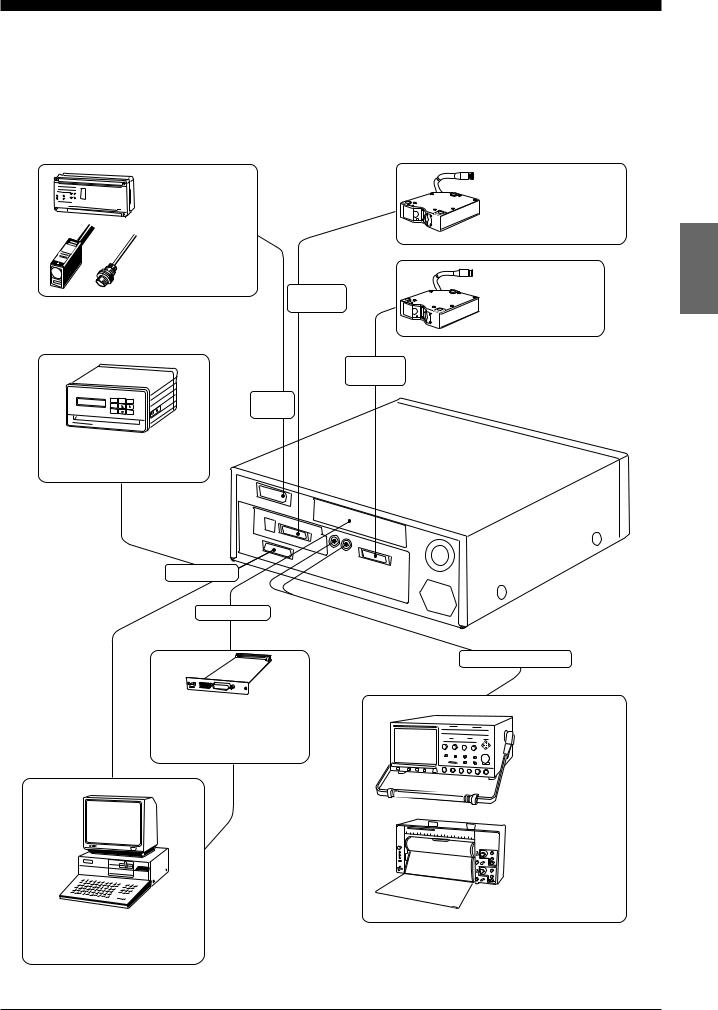
2-2 Expansion System Configuration
For flexible expansion, a variety of external equipment can be connected to the LC-2400 series, as shown below.
Connect a PLC |
, |
*1. |
|
|
|
||
photoelectric sensor , |
*1. |
||
or proximity sensor . |
|
*1. |
|
This port is used to switch memory banks, input auto-zero and hold signals, and output alarm signals.
Control
I/O port
With a commercially available printer connected, you can record measurement results.
RS-232C port
Expansion slot
With the DIGITAL I/O board (model: LC-B1) or GP-IBboard (model: LC-B2), you can send data to and receive it from
a personal computer.
You can send data to and receive it from a personal computer through one of the interface (RS-232C,
*1. |
GP-IB |
*1. |
DIGITAL I/O , |
). |
2ch sensor head port
1ch sensor head port
With the optionally available 2CH board (model:*1., *2. LC-B3), you can connect the second sensor head (model: LC-2420
/-2430/-2440/-2450) to the controller.
Connect the first sensor head (model: LC-2420
/-2430/-2440/-2450).
Analog voltage output
*1., *2.
*1., *2.
With an oscilloscope or pen recorder connected, you can monitor changes
in light intensity and target displacement through analog voltage signals.
*1. Optionally available from KEYENCE
*2. Cannot be used with the LC-2400W series.
CHAPTER 2 System Configuration |
7 |
|
2-3 Sensor Head Types and Functions
2-3 Sensor Head Types and Functions
The LC-2400 Series gives you a choice of 4 sensor head models.
LC-2420/LC-2430: Regular-reflective sensor heads
Regular-reflective sensor heads are used to measure targets having a highly reflective or mirror-like surface.
LC-2440/LC-2450: Diffuse-reflective sensor heads
Diffuse-reflective sensor heads are used to measure targets having a lowreflective or opaque surface.
8 |
CHAPTER 2 System Configuration |
|

2-4 Quick Reference Table
2-4 Quick Reference Table
Sensor setup, cable connections, and various parameters must be set before starting measurement. However, some of the parameters are not necessary, depending on system configuration and the type of measurements being done. The following table shows the procedures to follow, in
sequential order, before starting measurement. Find the items pertaining to your setup in the table to determine which sections of the manual are required reading.
Type of measurement
Trial measurement
Measuring height
Measuring eccentricity |
|
|
|
|
|
|
|
|
|
|
|
|
|
||
|
|
|
|
|
|
|
|
|
|
|
|
|
|
||
Measuring thickness |
|
|
|
|
|
|
|
|
|
|
|
|
|
||
Measuring difference in height |
|
|
|
|
|
|
|
|
|
|
|
|
|
||
|
|
Section No. |
|
|
Page No. |
|
|
|
|
|
|
|
|
||
5-1 |
|
Connecting Controller to Sensor Head |
p.22 |
R |
|
R |
R |
|
R |
|
R |
|
|
|
|
|
|
|
|
|
|
|
|
|
|
|
|
|
|
|
|
5-2 |
|
Connecting Power Supply Cable |
p.22 |
|
R |
R |
R |
|
R |
|
R |
|
|
|
|
|
|
|
|
|
|
|
|
|
|
|
|
|
|
|
|
5-3 |
|
Grounding Controller |
|
p.23 |
|
R |
R |
|
R |
|
R |
|
|
R |
|
5-4 |
|
Installing LC-B3 Board (2CH Sensor Head Board) |
p.24 |
R |
|
R |
|
|
|
|
|
|
|
|
|
|
|
|
|
|
|
|
|
|
|
|
|
|
|
|
|
5-5 |
Installing GP-IB or DIGITAL I/O Board |
|
p.24 |
|
|
|
|
|
|
|
|
|
|
||
|
|
|
|
|
|
|
|
|
|
|
|
|
|
|
|
5-6 |
|
Adjusting Sensor Head Position |
p.25 |
|
R |
R |
|
R |
|
R |
R |
|
|
||
|
|
|
|
|
|
|
|
|
|
|
|
|
|
|
|
6-1 |
Basic Operation of Controller |
p.28 |
|
R |
|
R |
|
R |
R |
|
|
|
|
||
|
|
|
|
|
|
|
|
|
|
|
|
|
|
|
|
6-2 |
Selecting Measurement Mode |
p.30 |
|
R |
R |
R |
|
R |
|
R |
|
|
|
|
|
6-3 |
Calibrating Sensitivity (Gain Selection) |
p.30 |
|
R |
R |
|
R |
|
R |
|
|
|
|
||
|
|
|
|
|
|
|
|
|
|
|
|
|
|
||
6-4 |
|
Selecting the Display/Output Mode |
p.31 |
R |
R |
|
|
|
|
|
|
|
|
||
|
|
|
|
|
|
|
|
|
|
|
|
|
|
|
|
6-5 |
|
Correcting Measurement Error (Calibration) |
p.32 |
R |
|
R |
R |
|
R |
|
|
|
|
|
|
|
|
|
|
|
|
|
|
|
|
|
|
|
|
|
|
6-6 |
Offset Values |
|
p.35 |
|
O |
|
O |
|
O |
|
|
O |
|
||
|
|
|
|
|
|
|
|
|
|
|
|
|
|
|
|
6-7 |
Reducing Variation in Measurement Data |
|
|
|
p.36 |
|
|
R |
R |
R |
R |
|
|||
|
|
(Setting Number of Averaging Measurements) |
|
|
|
|
|
|
|||||||
|
|
|
|
|
|
|
|
|
|
|
|
|
|
|
|
6-8 |
|
Reducing the Effect of Target Surface Irregularities |
|
|
|
p.36 |
|
|
O |
O |
O |
O |
|
||
|
|
(Setting Low-pass Filter Value) |
|
|
|
|
|
|
|||||||
|
|
|
|
|
|
|
|
|
|
|
|
|
|
|
|
6-9 |
|
Setting Range for Light Intensity (INT. LIMIT) |
p.37 |
|
O |
|
O |
|
O |
|
O |
|
|
|
|
|
|
|
|
|
|
|
|
|
|
|
|
|
|
||
6-10 Setting Upper/Lower Limits for Measurements |
|
|
|
p.39 |
|
|
O |
|
O |
O |
O |
|
|||
|
|
(Setting Tolerance) |
|
|
|
|
|
|
|
||||||
|
|
|
|
|
|
|
|
|
|
|
|
|
|
|
|
|
|
|
|
|
|
|
|
|
|
|
|
|
|
||
6-12 Storing and Loading Settings (Programming) |
p.41 |
R |
R |
R |
|
R |
|
|
|
|
|
|
|
||
|
|
|
|
|
|
|
|
|
|
|
|
|
|
|
|
7-1 |
Measuring with One Sensor Head |
p.44 |
|
|
|
|
|
R |
|
R |
|
|
|
|
|
7-2 |
Measuring with Two Sensor Heads |
p.45 |
|
R |
R |
|
|
|
|
|
|
|
|
|
|
R: Required reading
O: Optional reading
CHAPTER 2 System Configuration |
9 |
|

|
|
|
|
|
|
10 |
CHAPTER 2 System Configuration |
|

CHAPTER 3
PART NAMES AND FUNCTIONS
3-1 |
Controller ....................................................................... |
12 |
3-2 |
Sensor Head .................................................................. |
16 |

3-1 Controller
3-1 |
Controller |
|
|
|
|
|
|
|
|
|
|
|
|
|
|
|
|
|
Front Panel |
|
|
|
|
|
|
Display unit |
|
|
|
|
|
|
|
|
|
||
|
|
|
|
|
|
|
|
|
|
|
|
|
|
|
|
|
||
|
|
|
Display |
|
|
|
|
|
Operation keys |
|
|
|
|
|
LC-2400A |
|||
|
|
|
|
|
|
|
|
|
|
|
|
|
|
|
|
|
|
|
|
|
|
|
|
|
|
|
|
|
|
|
|
|
|
|
|
|
OFF |
|
|
|
|
|
|
|
|
|
|
|
LASER |
DISPLACEMENT |
METER |
LC-2400A |
|
|
|
|
|
|
|
|
|
|
|
|
mm |
NORMAL |
P–P |
PEAK |
BOTTOM |
|
|
ON |
|||
|
|
|
|
|
|
|
|
|
|
|
|
|
||||||
|
|
|
|
|
|
|
|
|
m |
|
|
|
|
|
|
|
|
POWER |
|
|
|
|
|
|
|
|
|
|
GAIN |
1CH |
2CH |
ADD |
SUB |
|
|
||
|
|
|
AUTO |
1 |
2 |
3 |
4 |
|
GAIN |
|
|
|
||||||
|
|
HIGH |
|
|
|
|
|
|
|
|
|
|
|
|
|
|
|
|
|
|
|
|
|
|
INT. ANALOG BAUD |
|
|
2–HEAD |
|
|
|
|
|
|
|
||
|
|
GO |
LIMIT |
OFFSET CAL |
LIMIT RATIO RATE DIGIT |
PRM |
|
|
|
|
|
|
|
|
|
|||
|
|
|
|
|
|
|
|
PRM |
AVERAGE |
FILTER |
INTENSITY |
ZERO |
|
|
LC-2400W |
|||
|
|
|
|
|
|
|
|
|
|
|
|
|||||||
|
|
LOW |
1 |
2 |
3 |
4 |
5 |
PROGRAM |
|
|
|
|
|
|
|
|
||
|
|
|
|
|
|
|
|
|
|
|
||||||||
|
|
|
|
|
|
|
|
|
|
|
|
|
|
|
|
|||
|
|
LASER |
ON |
|
|
|
|
LOCK |
LOAD |
|
|
|
|
HOLD |
|
|
STAND-BY |
|
|
|
|
|
|
|
|
|
|
|
|
|
|
||||||
|
OFF |
|
|
|
|
|
|
|
|
|
|
|
|
|
|
|
|
|
|
|
|
|
|
|
|
|
|
|
SAVE |
|
|
|
|
|
|
|
ON |
|
ON |
|
|
|
|
|
|
|
|
PROGRAM |
|
|
|
|
|
|
|
|
|
POWER |
|
|
|
|
|
|
|
|
|
|
|
|
|
|
|
|
|
|
|
|
|
|
|
|
|
|
|
|
|
|
|
|
|
|
|
POWER |
Key-operated power switch |
|
|
|
|
|
|
|
|
|
|
|
|
|
|
|
|
Reference: Refer to P.44. |
|
Display |
|
|
|
|
|
|
|
|
|
|
|
|
1 |
|
|
|
|
|
|
|
|
|
|
|
|
|
|
|
|
|
|
|
|
|
|
|
mm |
|
|
|
|
|
|
|
|
|
|
|
|
|
|
|
|
|
|
m |
|
|
|
|
|
9 |
|
|
|
|
|
AUTO |
1 |
|
2 |
3 |
4 |
|
GAIN |
|
|
|
|
|
|
|
HIGH |
|
|
|
|
|
|
|
|
|||
|
|
|
|
|
|
|
|
|
|
|
|
|
|
|
|
2 |
||
|
|
|
|
|
8 |
|
|
|
|
|
|
|
|
|
INT. |
ANALOG BAUD |
|
|
|
|
|
|
|
|
|
|
|
|
LIMIT |
OFFSET |
CAL |
DIGIT |
|
||||
|
|
|
|
|
|
|
|
GO |
|
LIMIT |
RATIO RATE |
PRM |
||||||
|
|
|
|
|
|
|
|
|
|
|
|
|
|
|
|
|||
|
|
|
|
|
|
|
|
|
|
|
|
|
|
|
|
|
||
|
|
|
|
|
7 |
|
|
|
|
|
|
|
|
|
|
|
|
3 |
|
|
|
|
|
|
|
LOW |
|
1 |
2 |
|
3 |
4 |
5 |
PROGRAM |
|||
|
|
|
|
|
|
|
|
|
|
|||||||||
|
|
|
|
|
|
|
|
|
|
|
|
|
|
|
||||
|
|
|
|
|
|
|
|
|
|
|
|
|
|
|
|
|
|
4 |
|
|
|
|
|
|
|
|
LASER |
ON |
|
|
|
|
|
|
|
|
LOCK |
|
|
|
|
|
6 |
|
|
|
|
|
|
|
|
|
|
|
|
5 |
No. |
Name |
|
|
|
|
|
|
|
|
|
|
Function |
|
|
Ref. page |
|||
1 |
Display panel |
|
Displays measured values, preset values and error mes- |
|
|
p.82 |
||||||||||||
|
|
|
|
|
|
sages. |
|
|
|
|
|
|
|
|
|
|||
|
|
|
|
|
|
|
|
|
|
|
|
|
|
|
|
|||
2 |
GAIN LEDs |
|
|
Indicates the receiver sensitivity. One of the four LEDs |
|
|
|
|||||||||||
|
|
|
|
|
|
corresponding to the current sensitivity will be lit. |
|
|
p.30 |
|||||||||
|
|
|
|
|
|
When the receiver sensitivity is set to AUTO, one of the four |
|
|||||||||||
|
|
|
|
|
|
|
|
|||||||||||
|
|
|
|
|
|
LEDs and the AUTO LED will be lit. |
|
|
|
|
|
|
||||||
3 |
PARAMETER LEDs |
Lights when setting parameters such as upper/lower toler- |
|
|
|
|
||||||||||||
|
|
|
|
|
|
ance limits, offset, calibration, intensity limit, analog ratio, |
|
p.28 |
||||||||||
|
|
|
|
|
|
baud rate and display digit. The LED corresponding to the |
|
|||||||||||
|
|
|
|
|
|
|
|
|||||||||||
|
|
|
|
|
|
parameter currently being changed lights. |
|
|
|
|
|
|||||||
4 |
PROGRAM LEDs |
|
The LED corresponding to the selected program number will |
|
|
|
p.41 |
|||||||||||
|
|
|
|
|
|
be lit. The LEDs blink during program selection. |
|
|
||||||||||
|
|
|
|
|
|
|
|
|
||||||||||
5 |
PANEL LOCK LED |
|
Lights when the operation keys are disabled. |
|
|
|
|
|
|
p.55 |
||||||||
6 |
Laser ON alarm LED |
|
Lights when the laser beam is ready to be and is being |
|
|
|
p.4., 26 |
|||||||||||
|
|
|
|
|
|
emitted from the sensor head. |
|
|
|
|
|
|
||||||
|
|
|
|
|
|
|
|
|
|
|
|
|
||||||
7 |
LOW LED |
|
Lights when a measured value falls below the preset lower |
|
|
p.39 |
||||||||||||
|
|
|
|
|
|
limit in each measurement mode. |
|
|
|
|
|
|
||||||
|
|
|
|
|
|
|
|
|
|
|
|
|
||||||
8 |
GO LED |
|
|
Lights when a measured value is within the preset tolerance |
|
|
p.39 |
|||||||||||
|
|
|
|
|
|
range of that measurement mode. |
|
|
|
|
|
|
||||||
|
|
|
|
|
|
|
|
|
|
|
|
|
||||||
9 |
HIGH LED |
|
|
Lights when a measured value exceeds the preset upper limit |
|
|
p.39 |
|||||||||||
|
|
|
|
|
|
of that measurement mode. |
|
|
|
|
|
|
|
|||||
|
|
|
|
|
|
|
|
|
|
|
|
|
|
|||||
12 |
CHAPTER 3 Part Names and Functions |
|
|
|
|
|
|
|
|
|
|
|
|
|
|
|
|
|
|
|
|
|
|
3-1 Controller |
|
|
|
|
|
|
|
|
|
|
|
|
|
|
|
|
|
|
|
|
|
|
|
|
|
|
|
Operation Keys |
|
|
|
|
|
|
|
|
|
|
|
|
|
|
|
|
|
|
|
|
|
|
|
|
|
|
|
|
|
|
0 |
|
|
A |
B |
C |
D |
|
|
|
|
||||||||
|
|
|
|
|
|
|
|
|
|
|
|
|
|
|
|
|
|
|
|
|
|
|
|
|
|
|
|
|
|
|
|
|
|
|
|
|
|
|
|
|
|
|
|
|
|
|
|
|
|
|
|
|
|
|
|
NORMAL |
|
|
P–P |
|
PEAK |
BOTTOM |
|
|
|
|
||||||||
|
|
|
R |
|
|
|
|
|
|
|
|
|
|
|
|
|
|
|
|
|
E |
|
|
|
|
|
|
|
|
|
|
|
|
|
|
|
|
|
|
|
|
|
|
|
|
|
|||
|
|
|
Q |
|
|
|
|
|
|
|
|
|
|
|
|
|
|
|
|
|
F |
|
|
|
|
|
|
|
|
|
|
|
|
|
|
|
|
|
|
|
|
|
|
|
|
|
|||
|
|
|
|
|
GAIN |
1CH |
2CH |
|
ADD |
SUB |
|
|
||||||||||||
|
|
|
|
|
|
|
|
|
|
|
||||||||||||||
|
|
|
P |
|
|
|
2–HEAD |
|
|
|
|
|
|
|
|
|
|
G |
|
|
||||
|
|
|
|
|
|
|
|
|
|
|
|
|
|
|
|
|
|
|
||||||
|
|
|
O |
|
|
|
|
|
|
|
|
|
|
|
|
|
H |
|
|
|||||
|
|
|
|
|
PRM |
AVERAGE |
FILTER |
|
INTENSITY |
ZERO |
|
|
|
|||||||||||
|
|
|
|
|
|
|
|
|||||||||||||||||
|
|
|
|
|
|
|
|
|
|
|
|
|
|
|
|
|
|
|
|
|
I |
|
|
|
|
|
|
|
|
|
|
|
|
|
|
|
|
|
|
|
|
|
|
|
|
|
|
||
|
|
|
|
|
|
|
|
|
|
|
|
|
|
|
|
|
|
|
|
|
|
|
||
|
|
|
N |
|
|
LOAD |
|
|
|
|
|
|
|
|
|
HOLD |
|
J |
|
|
||||
|
|
|
|
|
|
|
|
|
|
|
|
|
|
|
|
|
||||||||
|
|
|
M |
|
|
SAVE |
|
|
|
|
|
|
|
|
|
|
|
|
|
K |
|
|
||
|
|
|
|
|
|
|
|
|
|
|
|
|
|
|
|
|
|
|
||||||
|
|
|
|
|
|
|
|
|
|
|
|
|
|
|
|
|
|
|
|
|||||
|
|
|
|
|
|
PROGRAM |
|
|
|
|
|
|
|
|
|
|
|
|
|
|
|
|
|
|
|
|
|
|
|
|
|
|
|
|
|
|
|
|
|
|
|
|
|
|
|
|
|
||
|
|
|
|
|
|
|
|
|
|
|
|
|
|
|
|
|
|
|
|
|
|
|
|
|
|
|
|
|
|
|
|
|
|
|
|
|
L |
|
|
|
|
|
|
|
|
|
|
|
|
|
|
|
|
|
|
|
|
|
|
|
|
|
|
|
|
|
|
|
|
|
|
|
|
|
No. |
Name |
|
|
|
|
|
|
|
|
|
Function |
|
|
|
|
|
|
|
|
Ref. page |
|
|
||
|
|
|
|
|
|
|
|
|
|
|
|
|
|
|
||||||||||
0 |
NORMAL key |
Press this key to measure targets in the NORMAL mode. |
|
p.30 |
|
|
|
|
|
|
|
|
||||||||||||
|
|
|
|
|
|
|
|
|
|
|
|
|
|
|
|
|
|
|
|
|
|
|||
A |
P-P key |
Press this key to measure targets in the Peak-to-Peak mode. |
|
|
p.30 |
|
|
|
|
|
|
|
|
|||||||||||
|
|
|
|
|
|
|
|
|
|
|
|
|
|
|
|
|
|
|
|
|
|
|||
B |
2CH key |
Press this key to measure targets with the second sensor |
|
|
|
|
|
|
|
|
p.31, 45 |
|
|
|||||||||||
|
|
|
head (2CH slot) when two sensor heads are connected. |
|
|
|
|
|
|
|
|
|
|
|||||||||||
|
|
|
|
|
|
|
|
|
|
|
|
|
|
|||||||||||
C |
PEAK key |
Press this key to measure target in the PEAK mode. |
|
|
p.30 |
|
|
|
|
|||||||||||||||
D |
BOTTOM key |
Press this key to measure target in the BOTTOM mode. |
|
p.30 |
|
|
|
|
|
|
|
|
||||||||||||
|
|
|
|
|
|
|
|
|
|
|
|
|
|
|
|
|
|
|
|
|||||
E |
ADD key |
Press this key to measure thickness using two sensor heads. |
p.31, 46 |
|
|
|
|
|||||||||||||||||
|
|
|
|
|
|
|
|
|
|
|
|
|
|
|
|
|
|
|
|
|
|
|||
F |
SUB key |
Press this key to measure height deviation using two sensor |
|
|
|
|
|
|
|
|
p.31, 47 |
|
|
|||||||||||
|
|
|
heads. |
|
|
|
|
|
|
|
|
|
|
|
|
|
|
|
|
|
|
|||
|
|
|
|
|
|
|
|
|
|
|
|
|
|
|
|
|
|
|
|
|
|
|||
|
|
|
|
|
|
|
|
|
|
|
|
|
|
|
|
|
|
|
|
|
|
|||
G |
FILTER key |
Press this key to set a (Low-pass) FILTER value. |
|
|
|
p.36 |
|
|
|
|
||||||||||||||
H |
ZERO key |
Press this key to reset a measured value to "0". |
|
|
|
p.29 |
|
|
|
|
||||||||||||||
|
|
|
|
|
|
|
|
|
|
|
|
|
|
|
|
|
|
|
|
|
||||
I |
INTENSITY key |
Press this key to display received laser beam intensity. |
|
|
p.29 |
|
|
|
|
|||||||||||||||
|
|
|
|
|
|
|
|
|
|
|
|
|
|
|
|
|
|
|
|
|
|
|
||
J |
HOLD key |
Press this key to hold a measured value. |
|
|
|
|
|
p.29 |
|
|
|
|
||||||||||||
|
|
|
|
|
|
|
|
|
|
|
|
|
|
|
|
|
|
|
|
|
|
|
||
K |
ENTER key. |
Press this key to enter the value you set. |
|
|
|
|
|
p.28 |
|
|
|
|
||||||||||||
|
|
|
|
|
|
|
|
|
|
|
|
|
|
|
|
|
|
|
|
|
|
|
|
|
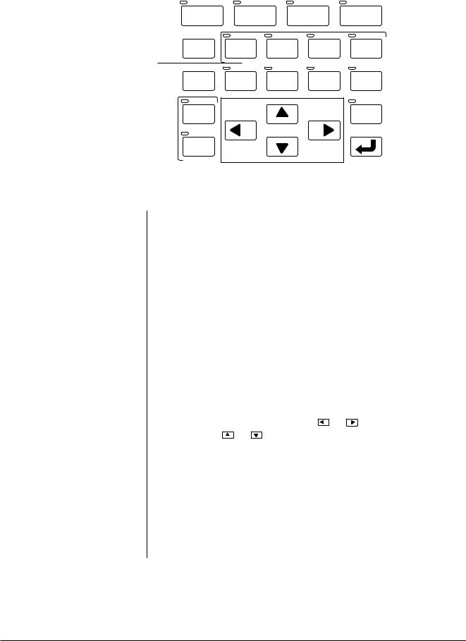
L |
Numeral change keys |
Press this key to change values. Press |
|
|
|
|
|
|
|
|
or |
|
to shift |
|
|
|
|
|||||||
|
|
|
digits and press |
or |
to increase or decrease values as |
|
p.28 |
|
|
|||||||||||||||
|
|
|
well as change signs. |
|
|
|
|
|
|
|
|
|
|
|
|
|
|
|
|
|
||||
M |
SAVE key |
Press this key to save a measured value. |
|
|
|
|
|
p.41 |
|
|
|
|
||||||||||||
|
|
|
|
|
|
|
|
|
|
|
|
|
|
|
|
|
|
|
|
|
|
|||
N |
LOAD key |
Press this key to load stored parameter settings. |
|
|
|
p.41 |
|
|
|
|
||||||||||||||
|
|
|
|
|
|
|
|
|
|
|
|
|
|
|
|
|
|
|
|
|
|
|
||
O |
PRM key |
Press this key to change parameter settings. |
|
|
|
|
|
p.28 |
|
|
|
|
||||||||||||
|
|
|
|
|
|
|
|
|
|
|
|
|
|
|
|
|
|
|
|
|
|
|||
P |
AVERAGE key |
Press this key to set the number of averaging measure- |
|
|
|
|
|
|
|
|
p.36 |
|
|
|||||||||||
|
|
|
ments. |
|
|
|
|
|
|
|
|
|
|
|
|
|
|
|
|
|
|
|||
|
|
|
|
|
|
|
|
|
|
|
|
|
|
|
|
|
|
|
|
|
|
|||
|
|
|
|
|
|
|
|
|
|
|
|
|
|
|
|
|
|
|
|
|
|
|
||
Q |
GAIN key |
Press this key to change receiver sensitivity. |
|
|
|
|
|
p.30 |
|
|
|
|
||||||||||||
R |
1CH key |
Press this key to use the first sensor head (1CH port) when |
|
|
|
|
|
|
|
|
p.31,44 |
|
|
|||||||||||
|
|
|
two sensor heads are connected. |
|
|
|
|
|
|
|
|
|
|
|
|
|||||||||
|
|
|
|
|
|
|
|
|
|
|
|
|
|
|
|
|||||||||
CHAPTER 3 Part Names and Functions |
13 |
|
3-1 Controller
Rear Panel
Display unit |
T |
|
U
Control unit
|
V |
X |
b |
S |
W |
||
|
|
|
POWER |
|
|
|
ON |
CONTROL I/O |
|
|
|
|
MONITOR |
|
|
HEAD No. |
HEAD No. |
|
OFF |
a
INTENSITY |
DISPLACEMENT |
100~240V AC |
|
||
RS-232C |
BATTERY LASER ON |
LASER |
|
|
REMOTE |


 LC–C1
LC–C1
|
|
|
FUSE 3.15A |
` |
] \ |
[ |
Z Y |
|
|
|
|
|
|
|
|
|
|
|
|
|
|
No. |
Name |
|
|
Function |
|
|
Ref. page |
|
|
S |
CONTROL I/O port |
|
Inputs signals (program, hold on/off, auto-zero on/off, etc.) |
|
p.71 |
||
|
|
|
|
|
|
from and outputs signals to external equipment. |
|
|
|
|
|
|
|
|
|
|
|
|
|
|
|
|
|
|
|
|
|
|
|
|
|
T |
INTENSITY output connector |
Outputs the laser beam intensity measured with the LC in |
|
|
p.74 |
||
|
|
|
|
|
|
analog voltage. |
|
|
|
|
|
|
|
|
|
|
|
|
|
|
|
|
|
|
|
|
|
|
|
|
|
U |
DISPLACEMENT output |
|
Outputs the measured displacement value as an analog |
|
|
p.73 |
|
|
|
|
connector |
|
voltage. |
|
|
||
|
|
|
|
|
|
|
|||
|
|
V |
Expansion I/O slot |
|
Install GP-IB board* or digital I/O board* in this slot. |
p.24, 95 |
|
||
|
|
W |
1CH sensor head connector |
|
Connect the 1CH sensor head to this connector. |
p.22 |
|
|
|
|
|
|
|
|
|
|
|
|
|
|
|
X |
Ventilating fan |
|
Radiates heat from the controller. |
|
p.16 |
|
|
|
|
|
|
|
|
|
|
|
|
|
|
Y |
Power supply connector |
|
Connect the power supply cable to this connector. |
p.22 |
|
|
|
|
|
|
|
|
|
|
|
|
|
|
|
Z |
F.G. terminal |
|
Ground the controller through this terminal. |
|
p.23 |
|
|
|
[ |
LASER REMOTE connector |
The LASER REMOTE connector is used to control laser |
|
|
|
|||
|
|
|
|
|
|
emission by an external input signal. When this connector |
|
p.11 |
|
|
|
|
|
|
|
is not used, be sure to connect the attached laser remote |
|
||
|
|
|
|
|
|
|
|
||
|
|
|
|
|
|
grounding plug to this connector. |
|
|
|
|
\ |
Laser ON alarm LED |
|
Lights when a laser beam is ready to be and is being |
|
|
p.18, 26 |
||
|
|
|
|
|
|
emitted from the sensor head. |
|
|
|
|
|
|
|
|
|
|
|
|
|
|
|
|
|
|
|
|
|
|
|
|
] |
BATTERY LED |
|
Lights when the internal backup battery is exhausted. |
|
p.15 |
|
||
|
|
|
|
|
|
|
|
|
|
|
^ |
RS-232C I/O port |
|
Connect a personal computer or other device to this port |
|
|
p.50 |
||
|
|
|
|
|
|
to externally control the LC. |
|
|
|
|
|
|
|
|
|
|
|
|
|
|
|
|
|
|
|
|
|
|
|
|
|
a |
LC-B3 board slot |
|
Install the optional LC-B3 board in this slot. |
|
p.24 |
|
|
|
|
|
|
|
|
The LC-B3 cannot be used with the LC-2400W series. |
|
|
|
|
|
|
|
|
|
|
|
|
|
|
|
b |
Power switch |
|
Use this switch to turn the main power supply on or off. |
|
|
||
|
|
|
|
|
|
(LC-2400W only) |
|
|
|
|
|
* Optionally available |
|
|
|
|
|
|
|
14 |
CHAPTER 3 Part Names and Functions |
3-1 Controller
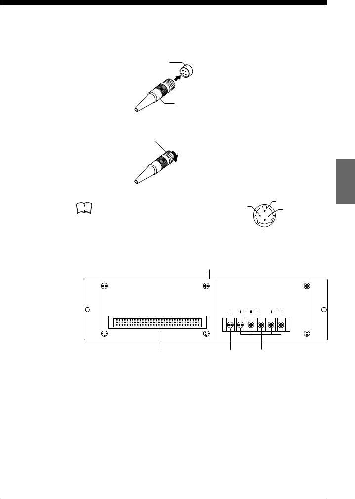
Laser Remote Grounding |
Follow the instructions below to insert this plug into the LASER REMOTE |
Plug |
connector. |
|
1. Check the connector’s orientation before insertion. |
|
LASER REMOTE |
|
connector |
Laser remote grounding plug
2. Turn the stopper clockwise to lock it in place.
|
Laser emission is enabled when pins 1 and 2 |
4 |
1 |
|
Note |
2 |
|||
of the connector are shorted. |
||||
|
|
|||
|
|
|
3 |
Control Unit Face
Control unit
DC |
|
DC |
|
DC |
DIGITAL I / O |
0V |
–15V |
+5V |
0V |
+15V |
b c d
No. |
Name |
|
Function |
Ref. page |
b |
96-pin DIGITAL I/O port |
The |
control unit is connected to the display unit via this |
|
|
|
|
connector. Digital signals are output through this connec- |
p.74 |
|
|
|
tor when the control unit is used separately from the |
|
|
|
|
|
|
|
|
|
display unit. |
|
|
|
|
|
|
c |
Earth ground terminal |
Ground the |
control unit through this terminal when using |
p.23 |
|
|
|
the control unit separately from the display unit. |
|
|
|
|
|
|
|
|
|
|
|
d |
Power supply terminals |
Connect the |
power supply cable to these terminals when |
p.23 |
|
|
|
using the control unit separately from the display unit. |
|
|
|
|
|
CHAPTER 3 Part Names and Functions |
15 |
|

3-2 Sensor Head
3-2 Sensor Head
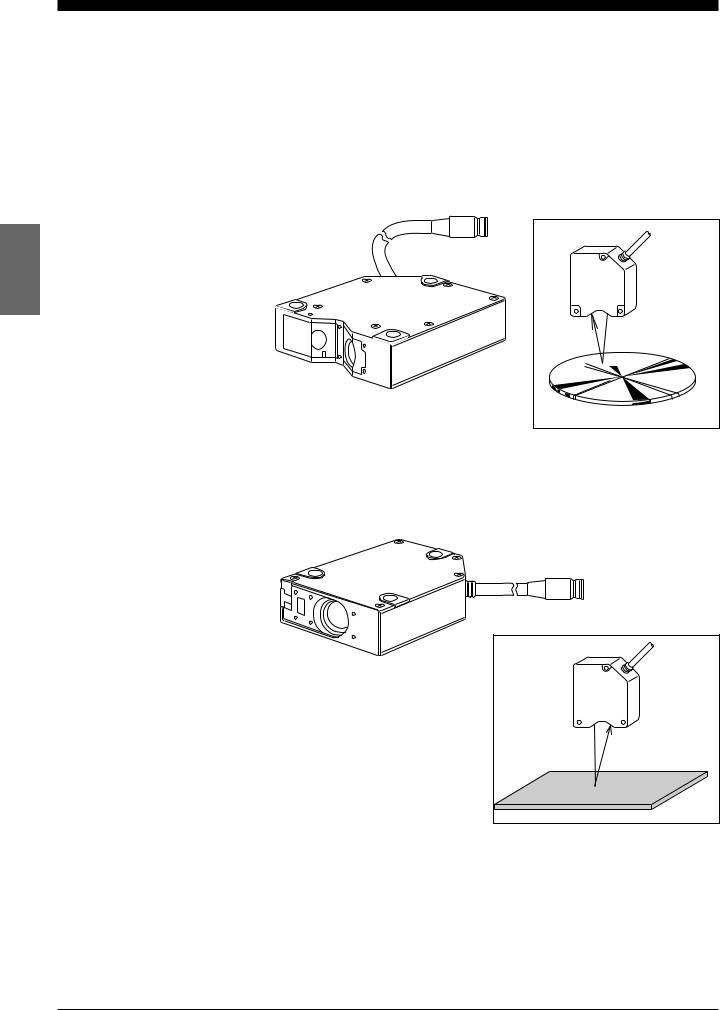
LC-2420/2430 (Regular-reflective)
h
i
e f g
LC-2440/2450 (Diffuse-reflective)
i
ef g h
No. |
Name |
|
Function |
|
|
Ref. page |
e |
Laser beam shield |
The laser |
beam shield is used to cover the laser beam |
|
|
|
|
|
|
transmitter. When operators are working near the sensor |
|
|
p.4 |
|
|
|
head, if there is a risk of looking directly at the laser beam, |
|
||
|
|
|
|
|
||
|
|
|
be sure to cover the transmitter with the shield. |
|
|
|
|
|
|
|
|
|
|
f |
Transmitter |
Emits |
laser beams. |
|
p.18 |
|
|
|
|
|
|
|
|
g |
Receiver |
Receives the reflected laser beam. |
|
p.18 |
|
|
|
|
|
|
|
|
|
h |
Cable connector |
Connects the sensor head cable to the controller. |
p.22 |
|
|
|
i |
Laser ON alarm LED |
Lights when a laser beam is ready to be and is being |
|
|
p.4, 26 |
|
|
|
|
emitted from the sensor head. |
|
|
|
|
|
|
|
|
|
|
16 |
CHAPTER 3 Part Names and Functions |

CHAPTER 4
OPERATING INSTRUCTIONS
4-1 |
Instructions for Using Controller and Sensor Head ............. |
18 |

4-1 Instructions for Using Controller and Sensor Head
Before operating the LC-2400 series, read the following instructions carefully. If you encounter any problems, please contact us.
4-1 Instructions for Using Controller and Sensor Head
After Receiving the
LC-2400 Series
Daily Maintenance
Instructions
•After receiving the LC, check the contents to see if any items were damaged during transportation.
•Check that all the items were included.
 Reference: Contents of the Package (p.ii)
• Before using the LC, be sure to read this instruction manual for details on the correct use of this product.
•Do not try to disassemble the LC or use a disassembled unit. Do not disassemble the sensor head in particular, since all of the sensor head parts have been factory-calibrated.
•Please handle the controller and sensor head with care. The precision optical components in the sensor head are especially susceptible to shock.
•The receiver and transmitter lenses are the critical components for accurate measurement. Any flaw or dust on the lenses may result in measurement errors. If dust has accumulated on the transmitter and receiver lenses, clean the lens surface by following the procedures given below.
1.Blow the dust off the receiver and transmitter lenses using a manual blower.
2.If dust persists, wipe the lens surface gently using a cotton swab dipped in alcohol.
18 |
CHAPTER 4 Operating Instructions |
4-1 Instructions for Using Controller and Sensor Head
Replacing Battery

 WARNING

 CAUTION
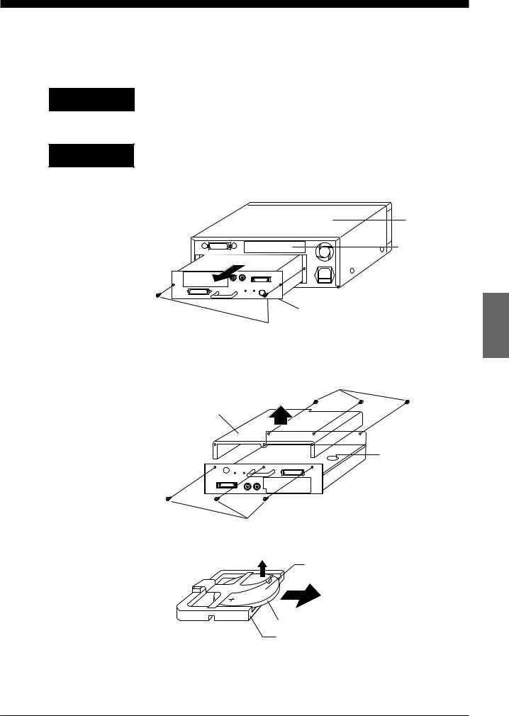
The LC controller has an internal backup battery for storing parameter settings. The expected battery life is 1 to 2.5 years. When the battery is exhausted, the BATTERY LED lights. When this LED is lit, replace the battery by following the procedure given below.
Danger of explosion if battery is incorrectly replaced. Replace only with the same or equivalent type recommended by the manufacturer. Dispose of
used batteries according to the manufacturer's instructions.
Turn the power OFF and unplug the power cable from the wall outlet.
1.Remove the two screws from the back of the display unit and remove the control unit.
Upper cover
Expansion slot
Control unit
Screws
2.Turn the control unit upside down, remove the six cover screws from the cover and then remove the cover.
Locate the battery holder in the control unit.
Screws
Cover
Battery holder
Screws
3. Remove the battery from the battery holder.
Positive side
Flat lithium battery: CR2032
Internal backup battery
Battery holder
4. Install the new battery in the battery holder with the positive side facing
up. When installing a new battery, be sure that the polarity of the battery is correct.
CHAPTER 4 Operating Instructions |
19 |
|

4-1 Instructions for Using Controller and Sensor Head
Instructions for Sensor Setup

 CAUTION
Hints on Correct Use
5.Put the cover back on the control unit and secure it with the six cover screws.
6.Reinsert the control unit into the display unit with the top of the control unit facing up, and secure the control unit with the two retaining screws.
Turn the power OFF when connecting or disconnecting the sensor head connector, power supply cables, or any of the optional boards. Otherwise, the laser diode or other electronic components may become degraded or damaged.
• Place the LC in a location that meets the following requirements:
Temperature: 0 |
to 40 |
° C |
Humidity: 35 |
to 85% RH (No condensation) |
|
Placing the LC in a location that does not meet these requirements may cause the controller and sensor head to malfunction.
Do not operate the LC in a location where extreme temperature variations are expected.
•Do not operate the LC where volatile flammable objects or corrosive gases are present.
•Do not expose the LC to extremely high humidity or water splashes.
•When using the control unit separately from the display unit, be sure to provide a protective cover for the control unit during operation.
•To prevent noise, keep the connection cables separate from the power cables. If this is not possible, shield or ground the connection cables.
•Insulate the sensor head if noise is transferred through the sensor head.
•Do not block the ventilation port or the ventilation fan of the controller. If they are blocked, the controller may overheat, resulting in a malfunction. Note also that a ventilation fan is not provided with the control unit. When using the control unit separately from the display unit, make sure that the room is sufficiently ventilated.
Ventilation port
Ventilation fan
•Keep the ambient temperature at a constant level during measurement.
•If the sensor head is operating in a location where there is thick fog or hot air, measurement errors may result.
•Be sure to leave the power on for at least 60 minutes before starting measurements.
20 |
CHAPTER 4 Operating Instructions |

CHAPTER 5
CONNECTIONS
5-1 |
Connecting Controller to Sensor Head .......................... |
22 |
5-2 |
Connecting Power Supply Cable ................................... |
22 |
5-3 |
Grounding Controller ..................................................... |
23 |
5-4 Installing LC-B3 Board (2CH Sensor Head Board) ....... |
24 |
|
5-5 |
Installing GP-IB or DIGITAL I/O Board .......................... |
24 |
5-6 Adjusting Sensor Head Position .................................... |
25 |
|
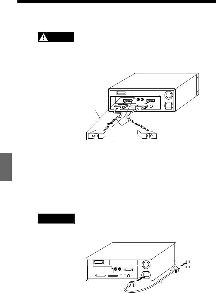
5-1 Connecting Controller to Sensor Head
5-2 Connecting Power Supply Cable
5-1 Connecting Controller to Sensor Head
The 2CH sensor head cannot be used with the LC-2400W series.
Turn the power OFF when connecting or disconnecting the sensor CAUTION head connector, power supply cables, or any of the optional boards.
Otherwise, the laser diode or other electronic components may become degraded or damaged.
Connect the controller to the sensor head using the supplied connecting
cable. At this time, make sure that the control unit and sensor head have the same serial number.
Options
Connecting cable
Sensor heads
2CH sensor head |
1CH sensor head |
If you purchase the LC-B3 and sensor head later, you can connect them to the controller without adjustment because the sensor head and the LC-B3 have been factory-calibrated as a pair.
5-2 Connecting Power Supply Cable
Connecting the Power
Supply Cable When
Using the Display Unit

 CAUTION
Turn OFF the LC controller before starting the following procedure. Plug the power supply cable into the power supply socket located on the rear of the display unit, and then into a wall outlet.
Power must be 100 to 240 VAC (50/60 Hz).
|
|
|
|
|
|
|
|
|
|
|
|
|
|
|
|
|
|
|
|
|
|
|
|
22 |
CHAPTER 5 Connections |
|
|
|
|

5-2 Connecting Power Supply Cable
5-3 Grounding Controller
Connecting the Power Supply Unit to a Separate Control Unit

 CAUTION

 CAUTION
Cannot be used with the LC-2400W series.
Turn OFF the power supply unit before starting the following procedure.
Connect the power supply unit to the power |
|
|
|
|
|
|
|
|
|
|
|
|
|
DC |
|
|
|
DC |
|
|
|
|
|
|
DC |
|
|
|
|
||||||||||||||||||||
supply terminals located on the front of the |
|
|
|
|
|
|
|
|
|
|
|
|
|
|
|
|
|
|
|
|
|
|
|
|
|
|
|
|
|
|
|
|
|
|
|
|
|
|
|
|
|
|
|
||||||
|
|
|
|
|
|
+15V |
0V |
|
–15V |
|
+5V |
|
|
|
|
||||||||||||||||||||||||||||||||||
control unit. |
|
|
|
|
|
|
|
|
|
|
|
|
|
|
|
|
|
||||||||||||||||||||||||||||||||
|
|
|
|
|
|
|
|
|
|
|
|
|
|
|
|
|
|
|
|
|
|
|
|
|
|
|
|
|
|
|
|
|
|
|
|
|
|
|
|
|
|
|
|
|
|
|
|||
|
|
|
|
|
|
|
|
|
|
|
|
|
|
|
|
|
|
|
|
|
|
|
|
|
|
|
|
|
|
|
|
|
|
|
|
|
|
|
|
|
|
|
|
|
|
|
|||
|
|
|
|
|
|
|
|
|
|
|
|
|
|
|
|
|
|
|
|
|
|
|
|
|
|
|
|
|
|
|
|
|
|
|
|
|
|
|
|
|
|
|
|
|
|
|
|||
|
|
|
|
|
|
|
|
|
|
|
|
|
|
|
|
|
|
|
|
|
|
|
|
|
|
|
|
|
|
|
|
|
|
|
|
|
|
|
|
|
|
|
|
|
|
|
|
|
|
|
|
|
|
|
|
|
|
|
|
|
|
|
|
|
|
|
|
|
|
|
|
|
|
|
|
|
|
|
|
|
|
|
|
|
|
|
|
|
|
|
|
|
|
|
|
|
|||
Note that the control unit uses the following types of power: |
|
|
|
|
|
|
|
|
|
|
|
|
|
|
|
|
|
|
|
|
|
|
|
|
|
|
|
|
|
|
|
|
|
|
|
|
|
|
|
|
|
|
|||||||
• |
± |
15 VDC ( |
± 3%), 0.5A |
|
|
|
|
|
|
|
|
|
|
|
|
|
|
|
|
|
|
|
|
|
|
|
|
|
|
|
|
|
|
|
|
|
|
|
|
|
|
|
|
|
|
||||
• |
± |
5 VDC ( |
± 5%), 3A, ripple (p-p): 100 mV max. |
|
|
|
|
|
|
|
|
|
|
|
|
|
|
|
|
|
|
|
|
|
|
|
|
|
|
|
|
|
|
|
|
|
|
|
|
|
|
|
|
|
|
||||
Be sure to supply ± 15 VDC and +5 VDC at the same time.
Supplying only +5 VDC may cause a malfunction.
5-3 Grounding Controller

 CAUTION
Grounding the
Controller When Using
the Display Unit
The controller can be grounded either by connecting the earth ground
terminal located on the rear of the display unit to a grounding electrode or by connecting the ground wire of the power supply cable to the ground screw of
a wall outlet. To prevent any risk of malfunction, ground the LC both ways as shown below.
Be sure to ground the controller separately from other devices.
Earth-ground the controller through the earth ground terminal located on the rear of the display unit with the ground wire of the power supply cable.
Grounding the Control |
Cannot be used with the LC-2400W series. |
|
|
|
|
|
|||||||
Unit |
Earth-ground the control unit through the earth ground terminal located on |
||||||||||||
|
|||||||||||||
|
the front of this unit. |
|
|
|
|
|
|||||||
|
|
|
DC DC |
|
|
DC |
|||||||
|
|
|
|
|
|
|
|
|
|
|
|
|
|
+15V 0V –15V +5V
CHAPTER 5 Connections |
23 |
|
 Loading...