


 Loading...
96M11664
Digital CMOS Laser Sensor
GV Series
Instruction Manual
Read this manual before using the software in order to achieve maximum performance.
Keep this manual in a safe place after reading it so that it can be used at any time.
Note |
|
The displayed values indicate guidelines for distances and should not |
be used in the actual applications for measurement.
Safety Precautions
|
• This product is only intended to detect object(s). Do not use this |
|
|
product for the purpose to protect a human body or part of a |
|
WARNING |
human body. |
|
• This product is not intended for use as an explosion-proof |
||
product. Do not use this product in a hazardous location and/or |
||
|
||
|
potentially explosive atmosphere. |
Safety Precautions on Laser Products
•This product employs a semiconductor laser for its light source.
•Use of controls or adjustments or performance of procedures other than those specified herein may result in hazardous radiation exposure.
•Follow the instructions mentioned in this manual. Otherwise, injury to the human body (eyes and skin) may result.
•Do not disassemble this product. Laser emission from this product is not automatically stopped when it is disassembled.
Precautions on class  /2 laser products
•Do not stare into the beam.
•Do not direct the beam at other people or into areas
WARNING |
where other people unconnected with the laser work |
might be present. |
•Be careful of the path of the laser beam.
If there is a danger that the operator may be exposed to the laser beam reflected by specular or diffuse reflection, block the beam by installing an enclosure with the appropriate reflectance.
•Install the products so that the path of the laser beam is not as the same height as that of human eye.
Precaution on class 1 laser products
• Do not stare into the beam.
Item |
Description |
||
Model |
|
GV-H45, GV-H130, |
GV-H45L, GV-H130L, |
|
GV-H450, GV-H1000 |
GV-H450L, GV-H1000L |
|
|
|
||
Wavelength |
|
655nm |
|
FDA (CDRH) |
Laser Class |
Class Laser Product |
Class 1 Laser Product* |
Part 1040.10 |
|
|
|
Output |
560μW |
220μW |
|
IEC 60825-1 |
Laser Class |
Class 2 Laser Product |
Class 1 Laser Product |
Output |
560μW |
220μW |
|
*The laser classification for FDA(CDRH) is implemented based on IEC60825-1 in accordance with the requirements of Laser Notice No.50.
Safety measures for the laser
Laser radiation emission indicator
The laser radiation emission indicator lights up after turning on the power and while the laser beam is being emitted.
Sensor amplifier |
Sensor head |
DATUM |
1 spot |
|
LASER |
|
|
1 |
|
SEL |
OUT |
|
|
2 |
|
|
SET |
|
MODE |
|
TIM |
|
|
|
|
BANK |
CLP |
series |
|
|
LASER |
|
1 |
|
OUT |
Laser radiation emission indicator |
2 |
Laser emission stop input
The laser emission stops when an emission stop (purple line) signal is input (for 20 ms or longer). The emission stops while the signal is input. The laser beam is emitted a maximum of 20 ms after the signal input is canceled. The control output functions according to the detection value even while laser emission stop is input.
Laser warning labels
The following diagrams show the type and position of laser warning labels according to the GV Series.
GV-H45(L)/GV-H130(L) GV-H450(L)/GV-H1000(L)
Aperture label |
|
Aperture label |
Aperture label |
|
|
Aperture label |
|
Laser |
|
transmitter |
Laser |
|
transmitter |
FDA (CDRH) |
FDA (CDRH) |
warning label (Class )* |
warning label (Class )* |
* Not included with GV-H45L/H130L/H450L/H1000L.
zAperture label
zFDA (CDRH) warning label (CLASS )
)
The FDA (CDRH) warning labels are only affixed to Class  laser products. z IEC warning/explanatory label (CLASS 2)
The IEC warning/explanatory labels are only included with Class 2 laser products.
When using this product in the countries and/or regions other than U.S., use the IEC warning/explanatory label in the package of this product.
In this case, it can be affixed on the FDA (CDRH) warning label, which has already been affixed to this product.
Checking the Package Contents
Check if the parts and equipment listed below are included in the package of the model you purchased before using the unit.
Sensor amplifier
GV-21/GV-21P (main unit) |
GV-22/GV-22P (expansion unit) |
|||||||
LASER |
DATUM |
|
|
LASER |
DATUM |
|
|
|
1 |
|
|
|
|
|
|||
OUT |
|
1spot |
|
1 |
|
1spot |
|
|
2 |
|
|
|
OUT |
|
|
|
|
SET |
|
|
|
2 |
|
|
|
|
1 |
|
|
SET |
|
|
|
|
|
|
2 |
|
|
|
1 |
|
|
|
|
|
|
|
|
2 |
|
|
|
|
BANK |
|
SEL |
|
BANK |
|
|
|
|
|
TIM |
|
|
|
SEL |
||
|
|
CLP |
|
|
|
TIM |
|
|
|
|
MODE |
|
|
CLP |
|
|
|
|
|
series |
|
|
|
|
MODE |
|
|
|
|
|
|
|
series |
||
|
|
|
|
|
|
|
||
Amplifier |
|
x1 |
Amplifier |
x1 |
|
|
||
Instruction manual |
x1 |
|
|
|
|
|
||
Sensor head |
|
|
|
|
|
|||
GV-H45(L)/H130(L) |
GV-H450(L)/H1000(L) |
|||||||
Sensor head |
x1 |
Sensor head |
x1 |
Insulating sheet |
x1 |
Insulating sheet |
X1 |
Mounting bracket |
x1 |
Mounting bracket |
x1 |
Board nut |
x1 |
Board nut |
x1 |
M3 x L30 screw |
x2 |
M4 x L35 screw |
x2 |
Laser warning sticker* x1 |
Laser warning sticker* x1 |
||
* This is not included with GV-H45L/H130L/H450L/H1000L.
We have thoroughly inspected the package contents before shipment. However, in the event of defective, broken or missing items, please contact your nearest KEYENCE office.
1 |
GV-IM-E |
Mounting and Wiring the Sensor Amplifier
Mounting the sensor amplifier
Mounting the GV-21/GV-21P (main unit)
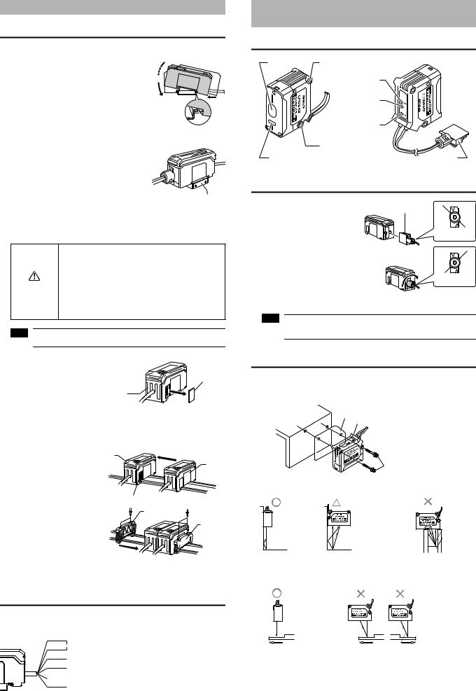
1 Align the claw at the bottom of the main body with the DIN rail. While pushing the main body in the direction of the arrow 1, slant it in the direction of the arrow 2.
2 To dismount the sensor, raise the main body in the direction of the arrow 3 while pushing the main body in the direction of the arrow 1.
When using the amplifier mounting bracket (OP-76877) (sold separately), mount it as shown in the diagram to the right.
(3) 
(2)
(1)
Amplifier mounting bracket
Mounting the GV-22/GV-22P (expansion unit)
Several expansion units can be used in connection with the main unit. Up to three expansion units can be connected to one main unit.
•When connecting multiple amplifiers (expansion units), first check to make sure that the power is turned off to all of the main and expansion units. Connecting the units with the power turned on may cause damage to the units.
• Push the amplifiers (expansion units) as far as possible into
CAUTION the main unit. If they are connected at a slant or not inserted securely, the units may be damaged.
•Only GV Series amplifier can be connected (DL Series cannot be connected). Connecting other amplifiers may cause damage to the units.
Note Expansion units with different output types (such as a PNP output main unit to an NPN output expansion unit) cannot be connected together.
1 Remove the expansion |
Expansion |
protective cover from the |
protective |
GV-21/GV-21P (main unit) |
cover |
|
GV-21/ |
|
GV-21P |
2 Install the amplifiers (expansion units) on the DIN rail.
For more information about mounting, see "Mounting the GV-21/GV-21P (main unit)".
3 Push the expansion unit into |
Main |
|
the main unit connector until |
unit |
Expansion |
a clicking sound can be |
|
unit |
heard. |
|
|
4 Install the end units |
|
Connector |
|
End |
|
(OP-26751: 2 units in a set) |
|
unit |
(sold separately) on either |
|
End |
side of the amplifiers (main or |
|
unit |
expansion units). Secure the |
|
|
end units in place with screws |
|
|
on top (2 on each end unit). |
|
|
The end units are mounted in the same way as the amplifiers.
Amplifier wiring
The following information shows the I/O cable.
For more information about the I/O circuit, see page 9 of this Instruction Manual.
Brown*1 |
|
|
|
*1 |
GV-22/GV-22P (expansion unit) do not |
|||
Blue*1 |
|
|
|
|
10-30 V DC |
|
have brown or blue lines. Power is supplied |
|
|
|
|
|
|
||||
Black |
|
|
|
|
to the expansion units through GV-21/GV- |
|||
|
|
Control output 1 |
|
21P (main unit). |
||||
White |
|
|
|
|
|
|||
|
|
Control output 2 |
*2 |
The external input switches as shown |
||||
|
|
|
|
|
||||
Pink*2 |
|
|
|
below depending on the amplifier |
||||
|
|
|
|
|||||
|
|
|
|
|
External input |
|
OPTIONAL settings. |
|
Purple |
|
|||||||
|
|
Laser emission |
|
• |
oFF ......... Input off |
|||
|
|
|
|
|
|
|||
|
|
|
|
|
stop input |
|
• |
SFt .......... External shift |
|
|
|
|
|
|
|
• |
bnK ......... Bank switching |
|
|
|
|
|
|
|
• |
tim ........... Timing input |
Connecting and Mounting the Sensor
Head
Sensor head part names
Laser receiver |
Mounting area |
|
LASER |
|
(Laser radiation |
|
emission indicator) |
|
OUT |
|
(Control output |
|
indicator) |
|
1spot |
|
(Spot reflection |
|
indicator) |
|
Mounting area |
Laser |
Connector |
Connecting the sensor head
1 Unlock the sensor head |
Connector |
connector and insert it into |
|
back of the amplifier. |
|
|
Unlocked |
2 Turn the round part of the
connector clockwise until a clicking sound is heard to lock it.
Locked
Note When shortening the sensor head cable, follow the instructions given in the "Sensor Head Connector Assembly Manual" included with the sensor head.
Mounting the sensor head
Use the dedicated mounting bracket to mount the sensor head.
When not using the dedicated mounting bracket, the included insulating sheet must be inserted between the mounting surface and the sensor head as shown in the diagram. (When using the dedicated mounting bracket, the insulating sheet is not necessary.)
Insulating sheet |
|
|
Sensor head |
|
Hexagon socket bolt |
|
(Accessory) |
z Mounting when detecting |
z Mounting when detecting |
targets close to a wall |
targets in a hole |
Receives little effect |
Variations in the detection |
The target cannot be detected |
from stray laser light. |
value with effects from |
when the transmitter or receiver |
|
stray laser light. |
are blocked. |
z When detecting uneven workpieces
• Stable detection |
• Incorrect values |
even on uneven |
can be detected |
areas. |
on the uneven |
|
areas. |
GV-IM-E |
2 |
Sensor Amplifier |
|
|
|
|
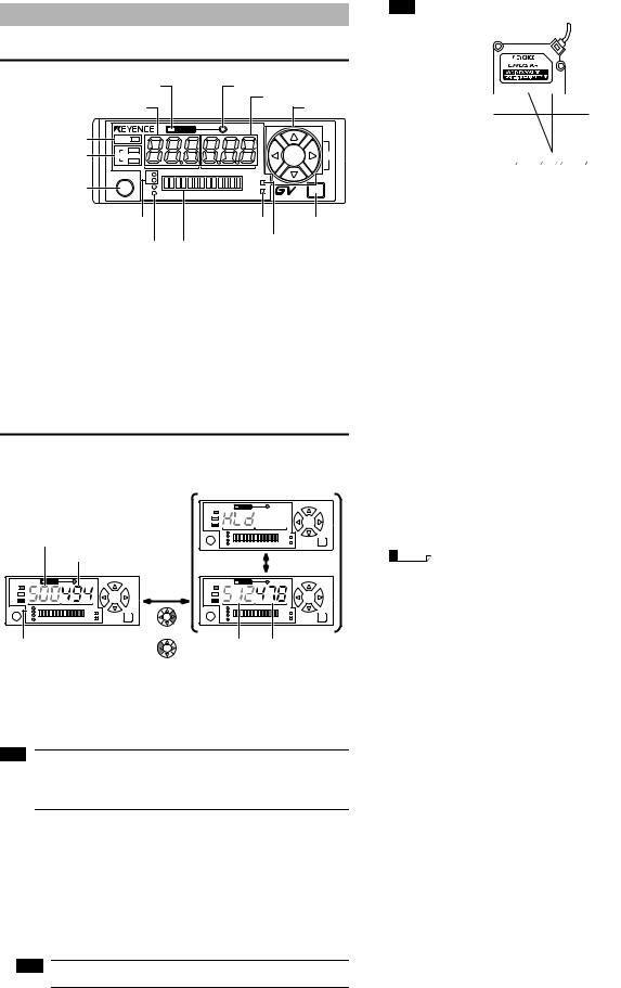
Sensor amplifier part names |
|
|
||
|
|
|
Spot reflection (1spot) indicator*2 |
|
Reference surface (DATUM) detection |
(green) |
|
||
indicator*1 (red) |
|
|
Current value display |
|
Setting value display (green) |
|
(red) |
Arrow |
|
|
|
|
|
buttons |
Laser radiation emission |
|
DATUM |
1 spot |
|
LASER |
|
|
|
|
indicator (green) |
1 |
|
|
|
Output status indicator |
|
|
SEL |
|
OUT |
|
|
||
(red) |
2 |
|
|
|
|
|
|
|
|
|
SET |
1 |
|
MODE |
[SET] button |
|
2 |
TIM |
|
|
|
|||
|
|
CLP |
|
|
|
|
BANK |
|
|
|
|
series |
|
|
|
|
|
|
|
|
Channel No. indicator (green) |
CLP function indicator*3 |
[MODE] button |
||||
|
Bank input indicator (green) |
|
|
|
(red) |
Timing input indicator*4 (red) |
|
|
|
|
|
LED bar |
|||
|
|
|
|||||
*1 |
The reference surface (DATUM) detection indicator lights up when |
||||||
|
performing reference surface detection. For more information, see |
||||||
|
"Reference surface detection (DATUM) method (Application)" on page 5 |
||||||
*2 |
of this Instruction Manual. |
|
|
|
|||
The spot reflection indicator lights up during normal detection and turns off |
|||||||
|
during multiple reflection (when multiple peaks of received light intensity |
||||||
|
occurs due to diffuse reflection), insufficient light intensity, and when the |
||||||
|
target is out of the detection range. |
|
|
|
|||
*3 |
For more information about the CLP (clamp) function indicator, see "4. |
||||||
|
Clamp function setting" on page 8 of this Instruction Manual. |
||||||
*4 |
For more information about the timing input indicator, see "8. External |
||||||
|
input setting" on page 8 of this Instruction Manual. |
|
|||||
Main screen
The main screen can be switched between "Current/setting value display" and "Peak/bottom value display". The main screen can be switched even during keylock.
Setting value (green) |
||
|
|
Current value (red) |
|
|
DATUM |
SET |
1 |
MODE |
2 |
||
or
|
|
DATUM |
SET |
1 |
MODE |
2 |
||
|
|
Alternate |
|
|
DATUM |
SET |
1 |
MODE |
2 |
Channel No. indicators |
Peak value (green) Bottom value (red) |
Setting value/current value display |
Peak value/bottom value display |
Pressing the [MODE] button switches |
Pressing the [UP] arrow button |
the channels (channel No. indicators). |
resets the peak and bottom values. |
Pressing the [Up] and [Down] arrow buttons simultaneously on the main screen forces the current value (red) to 0*.
*With the default settings. For details, see "9. Shift target value setting" on page 9 of this Instruction Manual.
Note When the channel No. 1 indicator is lit, the control output 1 (black line) setting value is displayed. When the channel No. 2 indicator is lit, the control output 2 (white line) setting value is displayed.
Operations are different in F-2 mode. (See page 5 of this Instruction Manual.)
zCurrent value and display resolution
In the default state, the current value shows 0 when the workpiece is located at the maximum detection distance. Bringing the workpiece closer to the sensor head gradually increases the value and displays it up to the minimum detection distance.
Item |
|
Current value |
|
||
GV-H45 (L) |
GV-H130 (L) |
GV-H450 (L) |
GV-H1000 (L) |
||
|
|||||
Detecting range (mm) |
20.0 to 45.0 |
55.0 to 130.0 |
160 to 450 |
200 to 1000 |
|
Digital display (initial) |
250 to 0 |
750 to 0 |
290 to 0 |
800 to 0 |
|
Display resolution |
1 |
2 |
1 |
5 |
|
Note The displayed values indicate guidelines for distances and should not be used in the actual applications for measurement.
Example When using sensor head GV-H130
Distance
0mm |
|
|
|
|
|
|
|
Current value |
|
||||
|
|
|
|
|
|
|
|
|
|||||
55mm |
|
|
|
|
|
|
|
|
750 |
Minimum detection distance |
|||
130mm |
|
|
|
|
|
|
|
|
|
|
0 |
Maximum detection distance |
|
|
|
|
|
|
|
|
|
|
|
|
|||
|
|
|
|
|
|
|
|
|
|
|
|
|
|
For example, when using the defaults with the setting value (green) at 500, the comparator output turns on when the current value is 500 or greater and turns off when it is less than 500.
If multiple reflection (when multiple peaks of received light intensity occurs due to diffuse reflection) occurs during F-1, F-2, or A-1 modes, the value immediately before the current value is held.
zSetting value
The following table shows the default setting values for each channel.
Operation |
Item |
|
Default value |
|
||
mode |
GV-H45 (L) |
GV-H130 (L) |
GV-H450 (L) |
GV-H1000 (L) |
||
|
||||||
|
Control output 1 (black) |
150 |
500 |
200 |
500 |
|
F-1, A-1, |
(Channel 1 lit) |
|||||
|
|
|
|
|||
A-2 |
Control output 2 (white) |
125 |
400 |
150 |
400 |
|
|
(Channel 2 lit) |
|||||
|
|
|
|
|
||
|
Control output 1 (black) HIGH |
150 |
500 |
200 |
500 |
|
|
(Channel 1 lit) |
|||||
|
|
|
|
|
||
|
Control output 1 (black) LOW |
100 |
300 |
100 |
300 |
|
F-2 |
(Channel 2 lit) |
|||||
|
|
|
|
|||
Control output 2 (white) HIGH |
125 |
400 |
150 |
400 |
||
|
||||||
|
(Channel 1 flashing) |
|||||
|
|
|
|
|
||
|
Control output 2 (white) LOW |
75 |
200 |
50 |
200 |
|
|
(Channel 2 flashing) |
|||||
|
|
|
|
|
||
zPeak/bottom values
Peak value: Resets when the detection value exceeds the setting value and holds the maximum value (peak value) until the detection value falls below the setting value again.
Bottom value: Resets when the detection value falls below the setting value and holds the minimum value (bottom value) until the detection value exceeds the setting value again.
Reference |
The held peak and bottom values can be cleared by pressing and hold |
|
the [Up] arrow button. |
3 |
GV-IM-E |
Loading...