


 Loading...
96104E
DeviceNet Compatible Network Unit
DL-DN1
User’s Manual (IB)
Read this manual before using the product in order to achieve maximum performance.
Keep this manual in a safe place for future reference.
Introduction
This manual describes the basic operations and hardware functions of the DL-DN1. Read the manual carefully to ensure safe performance and function of the DL-DN1.
Keep this manual in a safe place for future reference.
Ensure that the end user of this product receives this manual.
 Symbols
The following symbols alert you to matters concerning the prevention of injury and product damage.
|
|
|
It indicates a hazardous situation which, if not avoided, will result in |
|
DANGER |
|
|
|
|
death or serious injury. |
|
|
|
|
|
|
|
|
|
|
|
|
It indicates a hazardous situation which, if not avoided, could result |
|
WARNING |
|
|
|
|
in death or serious injury. |
|
|
|
|
|
|
|
|
|
|
|
|
It indicates a hazardous situation which, if not avoided, could result |
|
CAUTION |
|
|
|
|
in minor or moderate injury. |
|
|
|
|
|
|
|
|
|
|
|
|
It indicates a situation which, if not avoided, could result in product |
|
NOTICE |
|
damage as well as property damage. |
|
|
|
|
|
|
|
|
Important It indicates cautions and limitations that must be followed during operation.
 Point It indicates additional information on proper operation.

 Reference It indicates tips for better understanding or useful information.
Safety Precautions
General Precautions
•Before and while operating this product, confirm that it provides its functions and performance correctly.
•Implement sufficient safety measures to prevent human and physical damages in case this product fails.
•Be aware that the product functions and performance are not warranted if the product is used outside the range of stated specifications or is modified by the customer.
•Combining this product with other equipment requires sufficient consideration because the proper functions and performance may not be provided depending on the environment.
•Do not use this product in applications for human protection.
•Do not expose equipment, including peripherals, to rapid temperature changes. Equipment failure may result from dew condensation.
Precautions for Use
|
|
|
• In the following cases, immediately turn off the power. Leaving |
|
|
|
the equipment in unusual condition in may result in human |
|
|
|
injury or equipment failure. |
|
|
|
- Water or foreign matter entered the main unit; |
|
|
|
- The case is broken, for example if it is dropped; |
|
CAUTION |
|
- Smoke or unusual smell comes out of the product. |
|
|
|
|
|
|
|
• Use the correct power voltage. Failure to observe may result in |
|
|
|
injury or failure. |
|
|
|
• Do not disassemble or modify this product. Failure to observe |
|
|
|
may result in injury. |
|
|
|
|
Do not turn off the power while you are setting any item. Doing this
NOTICE
may cause loss of data settings wholly or partially.
Equipment Environment
For safe, trouble-free operation of this product, the product must not be installed in the following locations:
•Humid, dusty, or ill-ventilated.
•Exposed to direct sunlight or heating source.
•Exposed to corrosive or flammable gases.
•Exposed directly to vibration or shock.
•Exposed to water, oil, or chemical splashes.
•Exposed to static electricity.
96104E |
1 |
Safety Precautions
Noise Protection
If this product is installed in a location near a noise source, e.g., power source or highvoltage line, it may malfunction or fail because of noise. Use protection measures, such as using a noise filter or running the cables separately.
Notes on Regulations and Standards
CE Marking
The DL-DN1 conforms to the essential requirements of EMC Directive. The following harmonized standards are applied.
EMI: EN55011, Class A EMS: EN61000-6-2
2 |
- DeviceNet Compatible Network Unit DL-DN1 User's Manual - |

Safety Precautions
MEMO
- DeviceNet Compatible Network Unit DL-DN1 User's Manual - |
3 |

Relevant Manuals
The manuals relevant to this document are as follows:
Manuals relevant to CPU unit
Example: KV-5000 user's manual
Manuals relevant to
DeviceNet master unit
Example: KV-DN20 user's manual
This manual
Manuals of sensor amplifier main unit
Example:
GT2-70 series user's manualIG series user's manualFD-MH series instruction manual
KV- |
PLC CPU unit |
DN20 |
DeviceNet master unit |
MS |
NS
 ON
ON
TERM.
DL-DN1 (This unit)
Sensor amplifier
4 |
- DeviceNet Compatible Network Unit DL-DN1 User's Manual - |

Manual Organization
1 

2 

3 

4 

5 

Before Using
Connection and
Configuration
Communicating with the IB Series
Specifications
Appendix
This chapter provides an overview of the DL-DN1 and describes its part names and functions.
This chapter explains the procedures for connecting sensor amplifiers to the DL-DN1 and how to configure the data link.
This chapter describes the configuration of the memory linked to the DeviceNet master station and provides communication time charts.
This chapter describes the specifications and dimensions of the DL-DN1.
Provides the parameter list, as well as troubleshooting instructions.
1
2
3
4
5
- DeviceNet Compatible Network Unit DL-DN1 User's Manual - |
5 |

Table of Contents
Safety Precautions ........................................................................................ |
1 |
General Precautions ......................................................................... |
1 |
Precautions for Use ........................................................................... |
1 |
Notes on Regulations and Standards ............................................... |
2 |
Relevant Manuals .......................................................................................... |
4 |
Manual Organization ..................................................................................... |
5 |
Table of Contents .......................................................................................... |
6 |
Terms Used in This Document ..................................................................... |
8 |
Chapter 1 Before Using
1-1 |
DL-DN1 Overview .............................................................................. |
1-2 |
|
Overview ........................................................................................ |
1-2 |
|
Types and Number of Connectable Sensor Amplifiers .................. |
1-2 |
1-2 |
Checking the Package Contents ..................................................... |
1-3 |
|
Package Contents .......................................................................... |
1-3 |
1-3 |
Names and Functions of Each Part ................................................. |
1-4 |
Chapter 2 Connection and Configuration
2-1 |
Installation and Connection to Sensor Amplifiers |
......................... 2-2 |
|
ID Number Assignments to Sensor Amplifiers ............................... |
2-2 |
|
Installation and Connection to Sensor Amplifiers ........................... |
2-3 |
2-2 |
Wiring ................................................................................................. |
2-7 |
|
Connecting to the DeviceNet ......................................................... |
2-7 |
2-3 |
Configuring the Data Link .............................................................. |
2-10 |
|
Configuring the Master Unit ......................................................... |
2-10 |
|
Configuring the DL-DN1 ............................................................... |
2-11 |
Chapter 3 Communicating with the IB Series
3-1 |
Overview of DeviceNet Communication ......................................... |
3-2 |
|
Data Communicated Using DeviceNet ........................................... |
3-2 |
|
Overview of Communication Methods ........................................... |
3-3 |
3-2 |
I/O Communication ........................................................................... |
3-4 |
|
Selecting the DL-DN1 Operating Mode .......................................... |
3-4 |
|
Configuring the Operating Mode Setting Switch ............................ |
3-5 |
|
Occupied Memory .......................................................................... |
3-5 |
|
Device Maps .................................................................................. |
3-7 |
|
Communication Methods ............................................................. |
3-15 |
3-3 |
Explicit Messaging .......................................................................... |
3-20 |
6 |
- DeviceNet Compatible Network Unit DL-DN1 User's Manual - |

Table of Contents
|
Basic Formats of Explicit Messaging ........................................... |
3-20 |
|
Issuing a Motion Command to a Sensor Amplifier ....................... |
3-22 |
|
Reading/Writing Settings or Status of a Sensor Amplifier ............ |
3-23 |
|
Locking Sensor Amplifiers ............................................................ |
3-25 |
|
Command Parameter List ............................................................ |
3-26 |
|
|
|
Chapter 4 Specifications |
|
|
|
|
|
4-1 |
Specifications .................................................................................... |
4-2 |
4-2 |
Data Processing Times .................................................................... |
4-3 |
4-3 |
Dimensions ........................................................................................ |
4-5 |
|
|
|
Chapter 5 Appendix |
|
|
|
|
|
5-1 Connecting with Sensor Amplifiers ................................................ |
5-2 |
|
|
Connectable Sensor Amplifiers ...................................................... |
5-2 |
|
Mixed Connection of Sensor Amplifiers ......................................... |
5-3 |
5-2 |
DeviceNet Device Profile .................................................................. |
5-4 |
|
Device Profile ................................................................................. |
5-4 |
5-3 |
Troubleshooting ................................................................................ |
5-5 |
5-4 |
Index ................................................................................................... |
5-8 |
- DeviceNet Compatible Network Unit DL-DN1 User's Manual - |
7 |

Terms Used in This Document
This document uses the following terms:
Term |
Description |
|
|
Sensor |
A sensor amplifier. |
|
|
Master unit |
A DeviceNet master unit. |
|
|
Slave unit |
A DeviceNet slave unit. |
|
|
Main unit |
A sensor amplifier that has a power line and can operate |
|
alone. |
|
|
Expansion unit |
A sensor amplifier that does not have a power line and |
|
must be connected to a main unit. |
|
|
D-bus |
The name of KEYENCE's wiring-saving system for sensor |
|
amplifiers. |
|
For example, the high-precision contact type digital sen- |
|
sors of the GT2-70 series support this system. |
|
|
PGM |
A mode in which DeviceNet node addresses can be set by |
|
software. Explicit messaging is used for setting the |
|
addresses. |
|
|
8 |
- DeviceNet Compatible Network Unit DL-DN1 User's Manual - |
|
|
|
|
Before Using |
1 |
|
|
This chapter provides an overview of the DL-DN1 and describes its |
|
||
|
|
||
part names and functions. |
|
|
|
|
|
|
|
1-1 |
DL-DN1 Overview .............................................. |
1-2 |
1-2 |
Checking the Package Contents ........................ |
1-3 |
1-3 |
Names and Functions of Each Part.................... |
1-4 |
- DeviceNet Compatible Network Unit DL-DN1 User's Manual - |
1-1 |
1
Using Before
1-1 DL-DN1 Overview
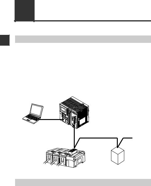
Overview
The DL-DN1 operates as a slave unit of DeviceNet communication. Using DeviceNet communications, the sensor amplifiers and other units connected to the DL-DN1 can transmit their ON/OFF control signals and current values as communication data to a PLC or other equipment.
The DL-DN1 supports DeviceNet I/O communication (polling) and explicit messaging. I/O polling enables data communication without the need of a ladder program. Explicit messaging allows for reading/writing sensor amplifier parameters and issuing motion commands to the sensor amplifiers.
System configuration example
KV- |
DN20 |
MS |
NS |
ON |
TERM. |
PLC or other host device (DeviceNet master unit)
DeviceNet slave unit
DL-DN1 (This unit)
D-bus compatible sensor amplifier
Types and Number of Connectable Sensor Amplifiers
The DL-DN1 can connect a maximum of 15 sensor amplifiers (main units and expansion units) which support D-bus. "D-bus" is the name of KEYENCE's wiring-saving system for sensor amplifiers.
Different types of sensor amplifiers with D-bus support can be connected to a single DL-DN1 unit.
How many and what types of sensor amplifiers can be connected depends on the sensor amplifiers or units to be connected. For details, refer to the user's manual of
your sensor amplifiers and  "Connecting with Sensor Amplifiers" (page 5-2) in this manual.
1-2 |
- DeviceNet Compatible Network Unit DL-DN1 User's Manual - |
1-2 Checking the Package Contents
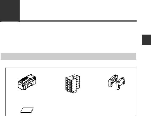
Before using the DL-DN1, make sure that the following equipment and accessories are included in the package.
We have thoroughly inspected the package contents before shipment. However, in the event of defective or broken items, contact your nearest KEYENCE office.
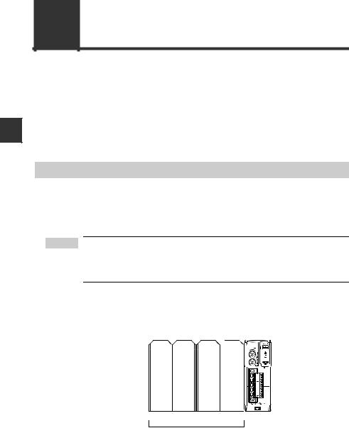
Package Contents
DL-DN1 main unit x 1 |
DeviceNet connector x 1 |
End unit x 2 |
Expansion connector |
Instruction Manual x 1 |
sticker x 1 |
|
1
Using Before
- DeviceNet Compatible Network Unit DL-DN1 User's Manual - |
1-3 |
1-3 Names and Functions of Each Part
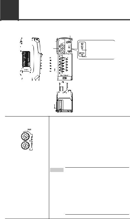
This section describes the part names and functions of the DL-DN1.
1 |
|
|
|
|
|
|
|
|
|
|
|
|
|
|
|
|
|
(1) Address setting switch |
|
(2) Operating mode setting switch |
||||||||||||||
|
|
|
|
|
|
|
|
|
|
|
|
|
|
|
|
|
|
|
||||||||||||||||
|
|
|
|
|
|
|
|
|
|
|
|
|
|
|
|
|
|
|
|
|
|
|
|
|
|
|
|
|
|
|
|
|
(3) |
Module status indicator (green/red) |
Before |
|
|
|
|
|
|
|
|
|
|
|
|
|
|
|
|
|
|
|
|
|
|
|
|
|
|
|
|
|
(4) |
Network status indicator (green/red) |
|||
Using |
|
|
|
|
|
|
|
|
|
|
|
|
|
|
|
|
|
|
|
|
|
|
|
|
|
|
|
|
|
|
|
|
(5)Sensorcommunicationindicator(green/red) |
|
|
|
|
|
|
|
|
|
|
|
|
|
|
|
|
|
|
|
|
|
|
|
|
|
|
|
|
|
|
|
|
|
|||
|
|
|
|
|
|
|
|
|
|
|
|
|
|
|
|
|
|
|
|
|
|
|
|
|
|
|
|
|
|
|
|
|||
|
|
|
|
|
|
|
|
|
|
|
|
|
|
|
|
|
|
|
|
|
|
|
|
|
|
|
|
|
|
(8) DeviceNet connector |
||||
|
|
|
|
|
|
|
|
|
|
|
|
|
|
|
|
|
|
|
|
|
|
|
|
|
|
|
|
|
|
|||||
|
|
|
|
|
|
|
|
|
|
|
|
|
|
|
|
|
|
|
|
|
|
|
|
|
|
|
|
|
|
|||||
|
|
|
|
|
|
|
|
|
|
|
|
|
|
|
|
|
|
|
|
|
|
|
|
|
|
|
|
|
|
|||||
|
|
|
|
|
|
|
|
|
|
|
|
|
|
|
|
|
|
|
|
|
|
|
|
|
|
|
|
|
|
|
||||
|
|
|
|
|
|
|
|
|
|
|
|
|
|
|
|
|
|
|
|
|
|
|
|
|
|
|
|
|
|
|
|
|
|
|
|
|
|
|
|
|
|
|
|
|
|
|
|
|
|
|
|
|
|
|
|
|
|
|
|
|
|
|
|
|
|
|
|
|
|
|
|
|
|
|
|
|
|
|
|
|
|
|
|
|
|
|
|
|
|
|
|
|
|
|
|
|
|
|
|
|
|
|
|
|
|
|
|
|
|
|
|
|
|
|
|
|
|
|
|
|
|
|
|
|
|
|
|
|
|
|
|
|
|
|
|
|
|
|
|
|
|
|
|
|
|
|
|
|
|
|
|
|
|
|
|
|
|
|
|
|
|
|
|
|
|
|
|
|
|
|
|
|
|
|
(6)Sensor amplifier connector 


 (for DIN rail mounting type)


(7)Sensor amplifier connector  (for panel mounting type
and large display type)
Item |
|
Description |
|
|
|
(1) Address setting switch |
Sets the DeviceNet node address of the DL-DN1. |
|
|
x10 |
: Ten's digit |
|
x1 |
: One's digit |
Setting range: 00 to 63 Default value: 63
When setting the node address of the DL-DN1 from the DeviceNet master unit, set it in the range of 64 to 99. The DL-DN1 is switched to PGM mode.
 Point When the DL-DN1 is set in the PGM mode and the power is turned on, the address of the DL-DN1 is the same as used when the DL-DN1was started last time.
When the DL-DN1 in the factory default setting is set to the PGM mode, the node address of the DL-DN1 is 63. Do not start multiple DL-DN1 units in factory default setting in the PGM mode, as that will result in a network error because of the duplicate node addresses.
1-4 |
- DeviceNet Compatible Network Unit DL-DN1 User's Manual - |
1-3 Names and Functions of Each Part
Item |
Description |
|
|
(2) Operating mode setSets the operating mode of the DL-DN1 in the DeviceNet. ting switch The data that can be handled in remote I/O communica-
tion varies with each operating mode.
Basic mode
Use switch bits 1 and 2 to configure the basic mode.
Switch setting |
Operating mode |
Occupied memory |
|||
|
|
|
|
IN area |
OUT area |
|
|
|
3-output mode |
8 byte |
0 byte |
|
|
|
|||
|
|
|
|
|
|
|
|
|
|
|
|
|
|
|
5-output mode |
12 byte |
0 byte |
|
|
|
|||
|
|
|
|
|
|
|
|
|
|
|
|
|
|
|
"3-output + current value" |
14 to 70 byte |
0 byte |
|
|
|
mode |
||
|
|
|
|
|
|
|
|
|
|
|
|
|
|
|
|
|
|
|
|
|
"5-output + current value" |
18 to 74 byte |
0 byte |
|
|
|
mode |
||
|
|
|
|
|
|
|
|
|
|
|
|
|
|
|
|
|
|
Default value: 3-output mode
•The contents of output and current value vary depending on the sensor amplifiers to be connected. Examples: 3-level judgment output for 3-output mode; 5-level judgment output for 5-output mode. Current value: comparator value.
•The size of occupied memory depends on the number of amplifiers to be connected.
Extended mode
Switch bits 3 and 4 can be set to add one of the following extended functions to the basic mode.
Switch setting |
Operating mode |
Occupied memory |
|||
|
|
|
|
IN area |
OUT area |
|
|
|
No extended mode |
- |
- |
|
|
|
|||
|
|
|
|
|
|
|
|
|
|
|
|
|
|
|
External input mode |
14 to 84 byte |
6 to 10 byte |
|
|
|
|||
|
|
|
|
|
|
|
|
|
|
|
|
|
|
|
"External input + |
|
|
|
|
|
BANK change" |
18 to 88 byte |
10 to 14 byte |
|
|
|
|||
|
|
|
mode |
|
|
|
|
|
|
|
|
|
|
|
"External input + |
22 to 96 byte |
24 to 40 byte |
|
|
|
setting value change" mode |
||
|
|
|
|
|
|
|
|
|
|
|
|
Default value: No extended mode
The size of occupied memory depends on the number of amplifiers to be connected.
1
Using Before
- DeviceNet Compatible Network Unit DL-DN1 User's Manual - |
1-5 |
1
Using Before
1-3 Names and Functions of Each Part
Item |
|
|
Description |
|
|
|
|
(3) Module status |
When normal: Lit in green |
||
indicator |
For details, see |
|
"Troubleshooting" (page 5-5). |
|
|||
(4)Network status indicator
(5)Sensor communicaIndicates the status of communication between the DL-
tion indicator |
DN1 and sensor amplifiers. |
||||||||||||||
|
|
|
|
|
|
|
|
|
When normal: Lit in green |
|
|
||||
|
|
|
|
|
|
|
|
|
|
|
|
|
|
|
|
|
|
|
|
|
|
|
|
|
For details, see |
|
"Troubleshooting" (page 5-5). |
||||
|
|
|
|
|
|
|
|
|
|
|
|
|
|
|
|
(6) Sensor amplifier |
Attach the sensor amplifier to this connector. |
||||||||||||||
connector (for DIN |
|
|
|
|
|
|
|
||||||||
rail mounting) |
|
|
|
|
|
|
|
||||||||
|
|
|
|
|
|
|
|
|
|
|
|
|
|
|
|
(7) Sensor amplifier |
Attach the sensor amplifier to this connector. |
||||||||||||||
connector (for panel |
When shipped from the factory, a protective sticker is |
||||||||||||||
mounting/large dis- |
installed. |
|
|
|
|
|
|||||||||
play) |
The optional expansion cable (OP-35361) is used for this |
||||||||||||||
|
|
|
|
|
|
|
|
|
connection. |
|
|
|
|
|
|
|
|
|
|
|
|
|
|
|
|
|
|
|
|
|
|
(8) DeviceNet connector |
Attach the DeviceNet cable to this connector. |
||||||||||||||
|
|
|
|
|
|
|
|
|
|
|
|
|
|
||
|
|
|
|
|
|
|
|
Black |
|
Wire color |
Signal name |
Function |
|
||
|
|
|
|
|
|
|
|
||||||||
|
|
|
|
|
|
|
|
|
Black |
V - |
|
Connects 0 VDC of the communication power supply. |
|
||
|
|
|
|
|
|
|
|
|
|
|
|
||||
|
|
|
|
|
|
|
|
Blue |
|
|
|
|
|
|
|
|
|
|
|
|
|
|
|
|
|
|
|
|
|
|
|
|
|
|
|
|
|
|
|
|
Blue |
CAN_L |
Communication signal (Low) |
|
|||
|
|
|
|
|
|
|
|
|
|
|
|||||
|
|
|
|
|
|
|
|
|
|
|
|
|
|
||
|
|
|
|
|
|
|
|
White |
|
Bare wire |
SHIELD |
Connects the shield of the DeviceNet cable. |
|
||
|
|
|
|
|
|
|
|
||||||||
|
|
|
|
|
|
|
|
|
|
|
|
|
|
|
|
|
|
|
|
|
|
|
|
Red |
|
White |
CAN_H |
Communication signal (High) |
|
||
|
|
|
|
|
|
|
|
||||||||
|
|
|
|
|
|
|
|
|
|
|
|
|
|
|
|
|
|
|
|
|
|
|
|
|
|
Red |
V + |
|
Connects 24 VDC of the communication power supply. |
|
|
|
|
|
|
|
|
|
|
|
|
||||||
|
|
|
|
|
|
|
|
|
|
||||||
|
|
|
|
|
|
|
|
|
|
|
|
|
|
|
|
|
|
|
|
|
|
|
|
|
|
|
|
|
|
|
|
1-6 |
- DeviceNet Compatible Network Unit DL-DN1 User's Manual - |
|
|
|
|
Connection and Configuration |
2 |
|
|
This chapter explains the procedures for connecting sensor |
|
||
|
|
||
amplifiers to the DL-DN1 and how to configure the data link. |
|
|
|
|
|
|
|
2-1 |
Installation and Connection to Sensor Amplifiers |
........ 2-2 |
2-2 |
Wiring ................................................................. |
2-7 |
2-3 |
Configuring the Data Link................................. |
2-10 |
- DeviceNet Compatible Network Unit DL-DN1 User's Manual - |
2-1 |
2-1 Installation and Connection to Sensor Amplifiers
This section provides the procedures for installing the DL-DN1 and connecting to sensor amplifiers.
The DL-DN1 can be connected with the expansion units of sensor amplifiers which support D-bus. ("D-bus" is the name of KEYENCE's wiring-saving system for sensor
2amplifiers.) How many sensor amplifiers can be connected depends on the sensor amplifiers or units to be connected. For specific numbers of connections, refer to the manual of each sensor amplifier.
Configuration and Connection
ID Number Assignments to Sensor Amplifiers
When connecting the DL-DN1 to a sensor amplifier which can be configured with expansion units, the main unit will be assigned ID number 01, with the expansion units assigned ID numbers of 02 to 04.
 Point • The ID number assignments to sensor amplifiers cannot be changed by the user.
•In this manual, ID number 01 to ID number 04 are denoted as ID 01 to ID 04, respectively.
For DIN rail mounting type
ID number 01 |
02 |
03 |
04 |
Main |
Expansion Expansion Expansion |
|
||
unit |
unit |
unit |
unit |
|
|
|
|
|
|
|
Sensor amplifier |
DL-DN1 |
||
2-2 |
- DeviceNet Compatible Network Unit DL-DN1 User's Manual - |
2-1 Installation and Connection to Sensor Amplifiers
For panel mounting type
ID number |
Sensor amplifier |
01 |
Main unit |
02 |
Sensor amplifier |
Expansionunit |
|
|
DL-DN1 |
03 |
Expansionunit |
04 |
Expansionunit |
 Point • Since ID numbers are assigned automatically, changing the number of sensor amplifiers or their connection sequence may require modification of the control program. In addition, some units are restricted in their connection sequence (e.g., a unit that must be the last connection). These considerations should be taken when configuring the control program.
•Changing the number of connected sensors may change the memory area reserved in the DL-DN1.
 "I/O Communication" (page 3-4)
•An error results if more sensor amplifiers are connected than the maximum number of connectable amplifiers.
 "Error information list" (page 3-8)
Installation and Connection to Sensor Amplifiers
Mounting on a DIN rail
1 Align the claw on the bottom of the amplifier with the DIN rail. While pushing the amplifier in the direction of arrow (1), press down in the direction of arrow (2).
(3)


(2)
(1)
2
Configuration and Connection
- DeviceNet Compatible Network Unit DL-DN1 User's Manual - |
2-3 |
2-1 Installation and Connection to Sensor Amplifiers
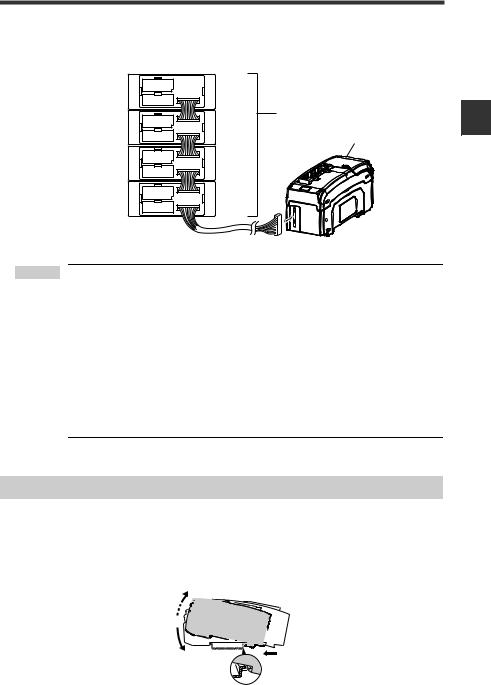
2To remove the DL-DN1, raise the main unit in the direction of arrow (3) while pushing it the direction of arrow (1).
Procedures for connecting to sensor amplifiers
The DeviceNet compatible communication unit DL-DN1 must be connected to sensor
2The connecting procedure varies with the mounting type of the sensor amplifiers to be connected.amplifiers before it can function.
Configuration and Connection
Make sure that the power to the sensor amplifier is off before starting to NOTICE connect the DeviceNet compatible communication unit, DL-DN1. Per-
forming the procedure with the power on may damage the DL-DN1.
 Point For the instructions on connecting additional sensor amplifiers, refer to the instruction manual of the sensors amplifiers.
● Connecting to sensor amplifiers (DIN rail mounting type)
1Remove the expansion protective cover from the sensor amplifier to be connected.
Sensor amplifier
Expansion protective cover
2Install the DeviceNet compatible communication unit, DL-DN1, on the DIN rail and connect to the sensor amplifier.
Ensure a tight connection, leaving no space between the DeviceNet compatible communication unit, DL-DN1, and the sensor amplifier.
Sensor amplifier |
DeviceNet compatible communication |
|
unit DL-DN1 |
Connector
2-4 |
- DeviceNet Compatible Network Unit DL-DN1 User's Manual - |
2-1 Installation and Connection to Sensor Amplifiers
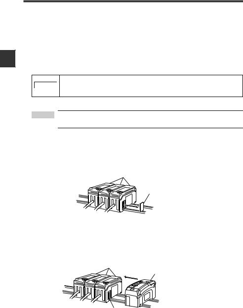
Make sure that the sensor amplifier connector (for DIN rail mounting type) is not askew on the side face of the DeviceNet compatible communication unit, DL-DN1, as shown below. If the connector is askew, the DLDN1 may become damaged when connected to the sensor amplifier.
Sensor amplifier connector
NOTICE
DeviceNet compatible communication unit DL-DN1
3Mount the supplied end units (OP-26751: a set of two pieces) on the outer side faces of the amplifier and the DeviceNet compatible communication unit, DL-DN1. Then, fix the end units with the screws on the top of each end unit (2 points x 2 units).
Mount the end units in the same way as the DeviceNet compatible communication unit, DL-DN1.
End unit
End unit
2
Configuration and Connection
Press the DeviceNet compatible communication unit DL-DN1 into full NOTICE engagement with the sensor amplifier. If the DL-DN1 is not correctly con-
nected, it may be damaged when the power is turned on.
- DeviceNet Compatible Network Unit DL-DN1 User's Manual - |
2-5 |
2
Configuration and Connection
2-1 Installation and Connection to Sensor Amplifiers
● Connecting to sensor amplifiers (panel mounting type)
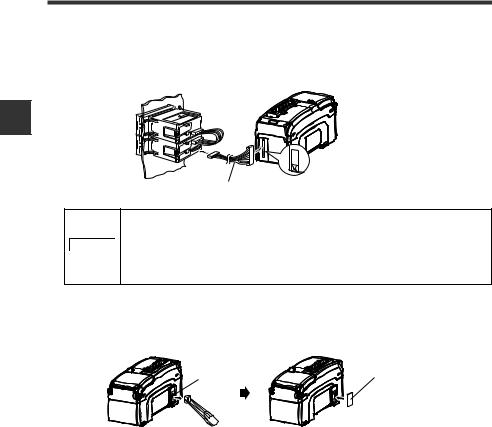
1Connect the optional expansion cable (OP-35361) between the sensor amplifier and the DeviceNet compatible communication unit, DL-DN1.
|
Peel off the protective sticker. |
|
Expansion cable (300 mm long) |
|
• Turn off the power and connect the expansion cable securely. If |
|
the cable is not correctly connected, the DL-DN1 may be |
NOTICE |
damaged when the power is turned on. |
|
• Do not attach or detach the cable with the power on, as this may |
|
damage the DL-DN1. |
2Remove the sensor amplifier connector (for DIN rail mounting type) from the DeviceNet compatible communication unit, DL-DN1, using pliers. In its place, attach the expansion connector sticker supplied with the DL-DN1.
Sensor amplifier connector |
Expansion connector sticker |
(for DIN rail mounting type) |
2-6 |
- DeviceNet Compatible Network Unit DL-DN1 User's Manual - |
2-2 Wiring
This section describes how to wire the DL-DN1.
Refer also to the DeviceNet Installation Manual published by ODVA.
 Point Turn off the power before wiring.
Connecting to the DeviceNet
Use the following procedure to connect the DL-DN1 to the DeviceNet.
Recommended cables
For connection between the DL-DN1 and the DeviceNet, use a dedicated DeviceNet cable conforming to the DeviceNet specifications or a dedicated flat cable.
 Point Do not use non-dedicated cables, as this may inhibit proper communication.
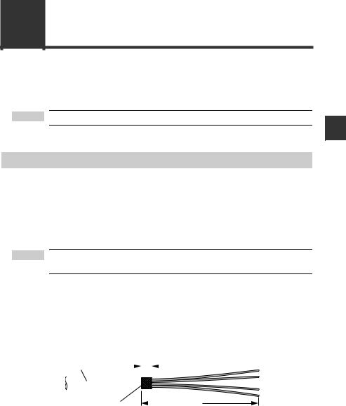
Trimming the cable
1 Strip the cable sheath.
Strip approximately 70 mm of cable sheath.
Make sure that the bare part of the shield braid is 6 mm or shorter.
Sheath |
|
|
|
|
|
|
6 mm or shorter |
||
|
|
|
|
|
|
|
|||
|
|
|
|
|
|
|
|
|
|
|
|
|
|
|
|
|
|
|
|
|
|
|
|
|
|
|
|
|
|
|
|
|
|
|
|
|
|
|
|
Shield braid
Approx. 70 mm
2
Configuration and Connection
- DeviceNet Compatible Network Unit DL-DN1 User's Manual - |
2-7 |
2
Configuration and Connection
2-2 Wiring
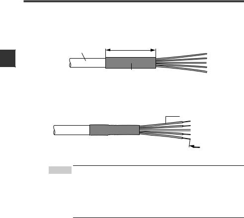
2Install a shrinkable tube.
Cover the exposed sheathed conductors and the sheath using a shrinkable tube approximately 40 mm long.
Approx. 40mm
Sheath
Shrinkable tube
3Strip the sheathed conductors.
Strip approximately 10 mm of sheath from the end of each conductor.
Sheathed conductor
Approx. 10mm 

 Point • If you are using solderless terminals, perform cable wiring/ trimming appropriately to suit the specifications of the particular terminals.
Recommended solderless terminals: Phoenix Contact's A/AI Series
•Do not perform soldering (pre-soldering) on the trimmed end of the cable.
2-8 |
- DeviceNet Compatible Network Unit DL-DN1 User's Manual - |
2-2 Wiring
Connecting the cable
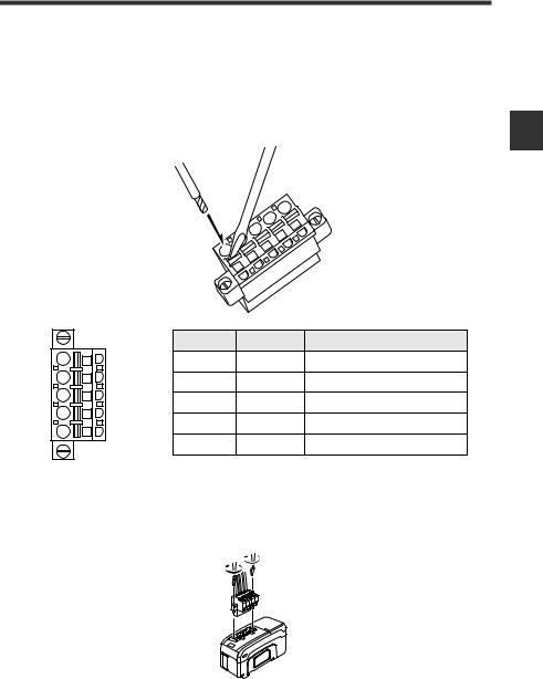
Use the following procedures to wire to the DeviceNet connector supplied with the DLDN1.
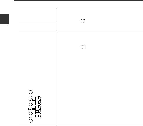
1Connect the trimmed cable to the DeviceNet connector.
Insert the cable completely. |
2 |
|
|
|
|
Configuration and Connection |
|
|
Wire color |
Signal name |
Function |
|
Black |
Black |
V - |
Connects 0 VDC of the communication power supply. |
|
Blue |
Blue |
CAN_L |
Communication signal (Low) |
|
|
||||
|
Bare wire |
SHIELD |
Connects the shield of the DeviceNet cable. |
|
White |
White |
CAN_H |
Communication signal (High) |
|
Red |
||||
|
|
|
||
|
Red |
V + |
Connects 24 VDC of the communication power supply. |
2Attach the DeviceNet connector to the DL-DN1.
Plug the connector into the DL-DN1 and secure it down with the screws on each end. (Tightening torque: 0.2 to 0.3 N•m)
- DeviceNet Compatible Network Unit DL-DN1 User's Manual - |
2-9 |
2
Configuration and Connection
2-3 Configuring the Data Link
Use the following procedure to connect the DL-DN1 to the DeviceNet system.
 Point This manual covers only the functions and settings of a DeviceNet master unit which are required for communication with the DL-DN1. For the functions and settings related to the communication between the DeviceNet master unit and CPU unit, refer to the manuals shipped with your master unit or CPU unit.
Configuring the Master Unit
The following configurations are required to connect the DL-DN1 to the DeviceNet master unit.
Slave attribute settings
Configure the master unit with the communication form, I/O size, and other information about the slave units. For this purpose, the EDS file for the DL-DN1 can be imported into the configuration software of the master unit.
|
Reference |
The EDS file can be downloaded from the KEYENCE web site: |
|
||
|
http://www.keyence.com |
|
|
|
Memory allocation settings
Configure the memory areas required for exchanging data through I/O communication. Do this using the configuration software of the master unit.
 Point • The memory allocations must be reconfigured if the number of connected sensors is changed, because the memory area reserved in the DL-DN1 may change.
•Cautions for connecting the Keyence master unit KV-DN20
Assign the memory allocation start address either to odd-num- bered addresses or to even-numbered addresses according to operating modes of the DL-DN1 (refer to page 2-11). The current value may not be read out correctly if the assignment is not proper. Assign to odd-numbered addresses:
3-output + current value (no extended) mode
5-output + current value (no extended) mode Assign to even-numbered addresses:
Operating modes other than the above
|
Reference |
Where multiple slave units are connected, the memory allocation for each |
|
||
|
slave unit is done automatically, based on the specified starting address. |
|
|
|
|
|
|
The allocation information for each slave unit can be checked using Devi- |
|
|
ceNet configuration software. |
2-10 |
- DeviceNet Compatible Network Unit DL-DN1 User's Manual - |
Loading...