


 Loading...
96132E
EtherNet/IP
Compatible Network Unit
DL-EP1
User’s Manual (IL)
Read this manual before using the product in order to achieve maximum performance.
Keep this manual in a safe place for future reference.
Introduction
This manual describes the basic operations and hardware functions of the DL-EP1. Read the manual carefully to ensure safe performance and function of the DL-EP1.
Keep this manual in a safe place for future reference.
Ensure that the end user of this product receives this manual.
 Symbols
The following symbols alert you to matters concerning the prevention of injury and product damage.
|
|
|
It indicates a hazardous situation which, if not avoided, will result in |
|
DANGER |
|
|
|
|
death or serious injury. |
|
|
|
|
|
|
|
|
|
|
|
|
It indicates a hazardous situation which, if not avoided, could result |
|
WARNING |
|
|
|
|
in death or serious injury. |
|
|
|
|
|
|
|
|
|
|
|
|
It indicates a hazardous situation which, if not avoided, could result |
|
CAUTION |
|
|
|
|
in minor or moderate injury. |
|
|
|
|
|
|
|
|
|
|
|
|
It indicates a situation which, if not avoided, could result in product |
|
NOTICE |
|
damage as well as property damage. |
|
|
|
|
|
|
|
|
 Important It indicates cautions and limitations that must be followed during operation.
 Point It indicates additional information on proper operation.

 Reference It indicates tips for better understanding or useful information.
It indicates reference pages.

Safety Information for DL-EP1
General Precautions
•Before and while operating this product, confirm its performance and functions operate correctly.
•Implement sufficient safety measures to prevent human and property damage in case this product fails.
•Be aware that the product functions and performance are not warranted if the product is used outside the range of stated specifications or is modified by the customer.
•Combining this product with other equipment requires sufficient consideration because the proper functions and performance may not be met depending on the environment.
•Do not use this product for the purpose of protecting a human body or a part of the human body.
•This product is not intended for use as an explosion-proof product. Do not use this product in hazardous locations and/or in a potentially explosive atmosphere.
•Do not expose equipment, including peripherals, to rapid temperature changes. Equipment failure may result from condensation build up.
Precautions for Use
•To avoid injury or failure, turn off the power immediately in the following cases.
-Water or foreign matter enters the main unit.
-The case is broken, for example if it is dropped.
CAUTION |
- Smoke or unusual smell is emitted from the product. |
•Use the correct power voltage. Failure to observe may result in injury, or failure.
•Do not disassemble or modify this product. Failure to observe may result in injury.
|
|
|
Do not turn off the power while you are setting any item. |
|
NOTICE |
|
|
|
|
Doing this may cause loss of data settings. |
|
|
|
|
|
|
|
|
|
Equipment Environment
For safe, trouble-free operation of this product, the product must not be installed in the following environments:
•Humid, dusty, or poorly ventilated.
•Exposed to direct sunlight or heat source.
•Exposed to corrosive or flammable gases.
•Exposed directly to vibration or shock.
•Exposed to water, oil, or chemical splashes.
•Exposed to static electricity.
96132E |
1 |

Noise Protection
If this product is installed in a location near an electrical noise source, e.g., a power source or high-voltage line, it may malfunction or fail because of noise. Take protective measures, such as using a noise filter or running the cables separately.
About the Power Supply
•Noise superimposed on the power supply may result in malfunction. Use a stabilized DC power supply configured with an isolation transformer.
•When using a commercially available switching regulator, be sure to ground the frame ground terminal.
Precautions on Regulations and Standards
UL Certification
This product is an UL/C-UL Listed product.
• |
UL File No. |
E207185 |
• |
Category |
NRAQ, NRAQ7 |
Be sure to consider the following specifications when using this product as an UL/C- UL Listed Product.
•Use this product under pollution degree 2.
•For wiring to the power supply connector, use a power supply with Class 2 output defined in NFPA70 (NEC: National Electric Code).
•This product is an open type device. Therefore, it must be installed in an enclosure with an IP 54 or higher rating. (e.g. Industrial control panel)
CE Marking
Keyence Corporation has confirmed that this product complies with the essential requirements of the applicable EC Directive, based on the following specifications. Be sure to consider the following specifications when using this product in a member state of European Union.
z EMC Directive (2004/108/EC)
EMI : EN55011, Class A EMS : EN61000-6-2
• Use an STP (shielded twisted pair) cable for connection to the network.
These specifications do not give any guarantee that the end-product with this product incorporated complies with the essential requirements of EMC Directive. The manufacturer of the end-product is solely responsible for the compliance on the endproduct itself according to EMC Directive.
2 |
- EtherNet/IP Compatible Network Unit DL-EP1 User’s Manual (IL) - |
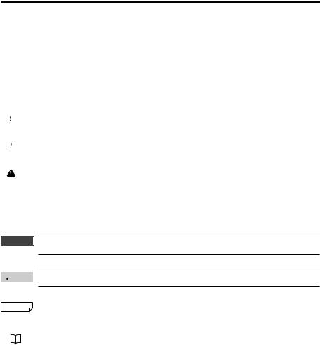
Relevant Manuals
The manuals relevant to this document are as follows:
Manuals related to CPU unit
Manuals related to
EtherNet/IP unit
This manual
Manuals for each sensor amplifier unit
Example) · IL series user's manual
KV- |
PLC CPU unit |
DN20 |
EtherNet/IP scanner |
MS |
|
NS |
unit |
ON |
TERM.
DL-EP1 (this unit)
Sensor amplifiers
- EtherNet/IP Compatible Network Unit DL-EP1 User’s Manual (IL) - |
3 |

MEMO
4 |
- EtherNet/IP Compatible Network Unit DL-EP1 User’s Manual (IL) - |

Manual Organization
1

2

3

4

5

Before Using
Connection and
Configuration
Communicating with the IL Series
Specifications
Appendix
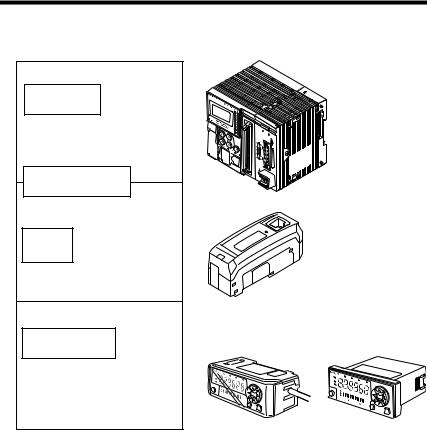
This chapter provides an overview of the DL-EP1 and describes its part names and functions.
This chapter describes the procedures from installing the DL-EP1 and sensor amplifiers to configuring communication.
This chapter describes the configuration of memory that communicates with the EtherNet/IP compatible network unit and a communication timing chart.
This chapter describes the specifications and external dimensions of the DL-EP1.
This chapter provides the parameter list, as well as troubleshooting instructions.
1
2
3
4
5
- EtherNet/IP Compatible Network Unit DL-EP1 User’s Manual (IL) - |
5 |

Table of Contents
Safety Information for DL-EP1 ..................................................................... |
1 |
General Precautions ...................................................................... |
1-1 |
Precautions for Use ........................................................................ |
1-1 |
Precautions on Regulations and Standards ................................... |
1-2 |
Relevant Manuals .......................................................................................... |
3 |
Manual Organization ..................................................................................... |
5 |
Table of Contents .......................................................................................... |
6 |
Terms Used in This Document ..................................................................... |
8 |
Chapter 1 Before Using
1-1 |
DL-EP1 Overview .............................................................................. |
1-2 |
|
Overview ........................................................................................ |
1-2 |
|
Connectable Sensor Amplifiers ...................................................... |
1-2 |
1-2 |
Checking the Package Contents ..................................................... |
1-3 |
|
Package Contents .......................................................................... |
1-3 |
1-3 |
Names and Functions of Each Part ................................................. |
1-4 |
Chapter 2 Connection and Configuration
2-1 Procedures from Installation before Using the DL-EP1 to |
|
|
|
Configuration .................................................................................... |
2-2 |
|
Configuration Procedures .............................................................. |
2-2 |
2-2 |
Installation and Connection to Sensor Amplifiers ......................... |
2-3 |
|
Mounting and connection to Sensor Amplifiers .............................. |
2-3 |
|
Assigning ID Numbers ................................................................... |
2-6 |
2-3 |
Wiring ................................................................................................. |
2-8 |
|
Connecting a communication cable ............................................... |
2-8 |
2-4 |
Configuring Communication with the DL-EP1 ............................. |
2-10 |
|
DL-EP1 Settings ........................................................................... |
2-10 |
2-5 |
Configuring Communication with the Scanner ............................ |
2-13 |
|
Setting the scanner ...................................................................... |
2-13 |
Chapter 3 Communicating with the IL Series
3-1 |
What is EtherNet/IP? ......................................................................... |
3-2 |
|
What is EtherNet/IP? ...................................................................... |
3-2 |
3-2 |
DL-EP1 EtherNet/IP Communication Function .............................. |
3-3 |
|
Overview of Communication Methods ........................................... |
3-3 |
3-3 |
Cyclic communication ...................................................................... |
3-5 |
|
Configuring Cyclic Communication ................................................ |
3-6 |
6 |
- EtherNet/IP Compatible Network Unit DL-EP1 User’s Manual (IL) - |
|

Actions which can be completed with Cyclic Communication |
........ 3-6 |
Usable Connections ....................................................................... |
3-7 |
Assignment to IN Area (DL-EP1 to Scanner) ................................. |
3-8 |
Assignment to OUT Area (Scanner to DL-EP1) ........................... |
3-16 |
Communication Methods ............................................................. |
3-18 |
Checking the Device Compatibility ............................................... |
3-21 |
3-4 Message Communication ............................................................... |
3-22 |
Configuring Message Communication ......................................... |
3-23 |
Actions which can be Completed with Message Communication ...... |
3-23 |
Objects and Services ................................................................... |
3-26 |
Objects Usable by DL-EP1 .......................................................... |
3-28 |
Basic Format and Processing Flow of Message Communication ...... |
3-29 |
Reading the DL Object Table ....................................................... |
3-31 |
DL Object (Class ID:67H) ............................................................. |
3-32 |
Using DL Object ........................................................................... |
3-48 |
Chapter 4 Specifications
4-1 |
Specifications .................................................................................... |
4-2 |
4-2 |
Data Processing Time ...................................................................... |
4-3 |
4-3 |
Dimensions ........................................................................................ |
4-5 |
Chapter 5 Appendix
5-1 |
Device Profile .................................................................................... |
5-2 |
5-2 |
Troubleshooting ................................................................................ |
5-3 |
5-3 |
Default Settings ................................................................................. |
5-5 |
5-4 Procedures for Communicating with an Allen-Bradley |
|
|
|
ControlLogix PLC ............................................................................. |
5-6 |
|
Procedures for Communicating with an Allen-Bradley ControlLogix PLC |
.. 5-6 |
|
Procedures for Communication with an Allen-Bradley SLC5/05 PLC 5-12 |
|
5-5 Objects Usable by DL-EP1 ............................................................. |
5-17 |
|
|
List of Usable Objects .................................................................. |
5-17 |
|
Reading Each Object Table ......................................................... |
5-18 |
|
Identity Object (Class ID: 01H) ..................................................... |
5-19 |
|
Message Router Object (Class ID: 02H) ...................................... |
5-22 |
|
Assembly Object (Class ID: 04H) ................................................. |
5-23 |
|
Connection Manager Object (Class ID: 06H) ............................... |
5-25 |
|
TCP/IP Interface Object (Class ID: F5H) ..................................... |
5-27 |
|
Ethernet Link Object (Class ID: F6H) ........................................... |
5-31 |
5-6 |
Index ................................................................................................. |
5-35 |
- EtherNet/IP Compatible Network Unit DL-EP1 User’s Manual (IL) - |
7 |

Terms Used in This Document
This document uses the following terms:
Term |
Description |
|
|
|
|
Sensor |
A sensor amplifier |
|
|
|
|
Scanner |
The EtherNet/IP scanner device |
|
|
|
|
Adaptor |
The EtherNet/IP adaptor device |
|
|
|
|
Main unit |
A sensor amplifier that has a power line and can operate |
|
alone |
||
|
||
|
|
|
Expansion unit |
A sensor amplifier that does not have a power line and must |
|
be connected to a main unit |
||
|
||
|
|
|
|
The name of KEYENCE's wiring-saving system for sensor |
|
D-bus |
amplifiers |
|
|
Supports IL Series CMOS laser amplifier sensors and others |
|
|
|
|
PLC |
Programmable logic controller |
|
|
|
|
Ladder program |
A program which controls the PLC |
8 |
- EtherNet/IP Compatible Network Unit DL-EP1 User’s Manual (IL) - |
|
|
|
|
Before Using |
1 |
|
|
This chapter provides an overview of the DL-EP1 and describes its |
|
||
|
|
||
part names and functions. |
|
|
|
|
|
|
|
1-1 |
DL-EP1 Overview............................................... |
1-2 |
1-2 |
Checking the Package Contents ........................ |
1-3 |
1-3 |
Names and Functions of Each Part.................... |
1-4 |
- EtherNet/IP Compatible Network Unit DL-EP1 User’s Manual (IL) - |
1-1 |
1
Using Before
1-1 DL-EP1 Overview
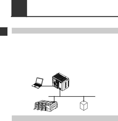
Overview
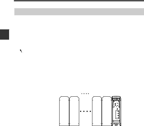
The DL-EP1 operates as an EtherNet/IP communication adaptor. EtherNet/IP communications enable you to output the ON/OFF control signals and current values of the DL-EP1 and sensor amplifiers connected to the DL-EP1 as communication data to a PLC or other equipment.
The DL-EP1 supports EtherNet/IP cyclic communication (Implicit messaging) and message communication (Explicit messaging). Cyclic communication enables data exchange without a ladder program. Message communication allows for reading/ writing sensor amplifier parameters and issuing commands to the sensor amplifiers.
■ System configuration example
PLC or other host device (EtherNet/IP unit)
EtherNet
EtherNet/IP adaptor
DL-EP1 (this unit)
Connectable Sensor Amplifiers
■ Number of Connectable Sensor Amplifiers
Name |
Amplifier form |
Main unit |
Expansion |
Maximum number of |
|
|
|
|
unit |
connectable units |
|
|
DIN rail mount |
IL-1000 |
IL-1050 |
8 |
|
IL Series |
type |
|
|
(1 main unit, 7 expansion units) |
|
Panel mount |
IL-1500 |
IL-1550 |
8 |
||
|
|||||
|
type |
(1 main unit, 7 expansion units) |
|||
|
|
|
|||
|
|
|
|
|
Sensor amplifiers supporting D-bus are connectable. You can connect one sensor to the DL-EP1 as a main unit and one or more sensors to the main unit as expansion units. (D-bus is the name of KEYENCE's wiring-saving system for sensor amplifiers.) If the sensor amplifier is D-bus compatible, different models can be connected together.
How many and what types of sensor amplifiers can be connected depends on the sensor amplifiers or units to be connected. Please inquire for details.
1-2 |
- EtherNet/IP Compatible Network Unit DL-EP1 User’s Manual (IL) - |
1-2 Checking the Package Contents
Before using the DL-EP1, make sure that the following equipment and accessories are included in the package. We have thoroughly inspected the package contents before shipment.
However, in the event of defective or broken items, contact your nearest KEYENCE office.
Package Contents
■ Package contents |
|
|
DL-EP1 main unit x 1 |
Expansion connector |
End unit x 2 |
|
sticker x 1 |
OP-26751 |
Instruction manual x 1
■List of Optional Parts
•STP (shielded twisted pair) cable
(Category 5e, straight) - OP-51504 (0.2m)
- OP-51505 (0.5m)
- OP-51506 (1m)
-OP-51507 (3m)
-OP-51508 (5m)
*The working ambient temperature of the above cables are 0 to 50°C.
1
Using Before
- EtherNet/IP Compatible Network Unit DL-EP1 User’s Manual (IL) - |
1-3 |
1
Using Before
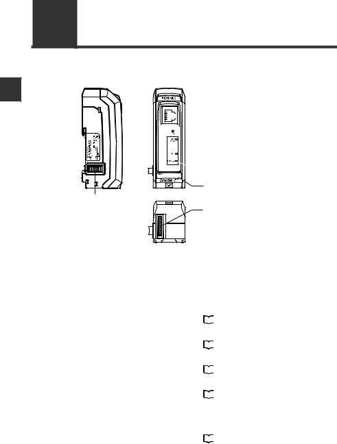
1-3 Names and Functions of Each Part
This section describes the part names and functions of the DL-EP1.
(8)Sensor amplifier connector (for DIN rail mount type)
 (1) RJ-45 connector


 (2) Reset switch
 (3) Link/activity indicator (green)

 (4) Module status indicator (green/red)
 (5) Network status indicator (green/red)
 (6) Sensor communication indicator (green/red)
(7) MAC address
(9) Sensor amplifier connector (for panel mount type
and large display type)
|
Name |
|
|
Description |
|
|
|
|
|
(1) |
RJ-45 connector |
Attach the network cable to this connector. |
||
|
|
|
|
|
(2) |
Reset switch |
When held down for three seconds or longer, the DL-EP1 |
||
|
|
settings will be reset to the default settings. |
||
|
|
For details, refer to |
|
"Default Settings" (Page 5-5). |
|
|
|
||
|
|
|
|
|
(3) |
Link/activity |
Normal: Green LED lights up or blinks |
||
|
indicator |
For details, refer to |
|
"Troubleshooting" (Page 5-3). |
|
|
|||
|
|
|
|
|
(4) |
Module status |
Normal: Green LED lights up |
||
|
indicator |
For details, refer to |
|
"Troubleshooting" (Page 5-3). |
|
|
|||
|
|
|
|
|
(5) |
Network status |
Normal: Green LED lights up |
||
|
indicator |
For details, refer to |
|
"Troubleshooting" (Page 5-3). |
|
|
|||
|
|
|
|
|
(6) |
Sensor communication |
Indicates the status of communication between the DL- |
||
|
indicator |
EP1 and sensor amplifiers. |
||
|
|
Normal: Green LED lights up |
||
|
|
For details, refer to |
|
"Troubleshooting" (Page 5-3). |
|
|
|
||
|
|
|
|
|
(7) |
MAC address |
MAC address for this DL-EP1 |
||
|
|
|
|
|
(8) |
Sensor amplifier |
Attach the sensor amplifier to this connector. When not |
||
|
connector (for DIN rail |
using this connector, remove it and replace with the |
||
|
mount type) |
protective sticker. |
|
|
|
|
|
|
|
1-4 |
- EtherNet/IP Compatible Network Unit DL-EP1 User’s Manual (IL) - |

|
|
1-3 Names and Functions of Each Part |
|
|
|
|
|
|
|
|
|
|
Name |
Description |
|
|
|
|
|
|
(9) Sensor amplifier |
Attach the sensor amplifier to this connector. A protective |
|
|
connector (for panel |
seal is attached when shipped from the factory. The |
|
|
mount/large display |
optional expansion cable (OP-35361) is used for this |
|
|
type) |
connection. |
|
|
|
|
|
1
Using Before
- EtherNet/IP Compatible Network Unit DL-EP1 User’s Manual (IL) - |
1-5 |

1-3 Names and Functions of Each Part
MEMO
1
Using Before
1-6 |
- EtherNet/IP Compatible Network Unit DL-EP1 User’s Manual (IL) - |
|
|
|
|
Connection and Configuration |
2 |
|
|
This section describes procedures from installing the DL-EP1 and |
|
||
|
|
||
sensor amplifiers to configuring communication. |
|
|
|
|
|
|
|
2-1 |
Procedures from Installation before Using the DL-EP1 to |
|
|
Configuration........................................................... |
2-2 |
2-2 |
Installation and Connection to Sensor Amplifiers ... |
2-3 |
2-3 |
Wiring ................................................................. |
2-8 |
2-4 |
Configuring Communication with the DL-EP1 .. 2-10 |
|
2-5 |
Configuring Communication with the Scanner . 2-13 |
|
- EtherNet/IP Compatible Network Unit DL-EP1 User’s Manual (IL) - |
2-1 |

2-1 Procedures from Installation before Using the DL-EP1 to Configuration
2
Configuration and Connection
This section describes the procedures before you use the DL-EP1.
Configuration Procedures
1. Installation and Connection to Sensor Amplifiers
Connecting the DL-EP1 to sensor amplifiers (Page 2-4)
Assigning ID Numbers (Page 2-6)
2. Wiring
Connecting a communication cable (Page 2-8)
3. Configuring Communication with the DL-EP1
Setting the IP address (Page 2-10)
4. Configuring Communication with the Scanner
Setting the IP address (Page 2-13)
Registering the device profile of the DL-EP1 (Page 2-13)
Configuring the Scanner Side (Refer to each scanner manual.)
The above configurations enable communication.
For the outline of scanner side configuration for communication with an Allen-Bradley
scanner, refer to  "Procedures for Communicating with an Allen-Bradley ControlLogix PLC" (Page 5-6).
2-2 |
- EtherNet/IP Compatible Network Unit DL-EP1 User’s Manual (IL) - |

2-2 Installation and Connection to Sensor Amplifiers
Number of Connectable Sensor Amplifiers
Name |
Amplifier form |
Main unit |
Expansion |
Maximum number of |
|
|
|
|
unit |
connectable units |
|
|
DIN rail mount |
IL-1000 |
IL-1050 |
8 |
|
IL Series |
type |
|
|
(1 main unit, 7 expansion units) |
|
Panel mount |
IL-1500 |
IL-1550 |
8 |
||
|
|||||
|
type |
(1 main unit, 7 expansion units) |
|||
|
|
|
|||
|
|
|
|
|
This section describes how to mount the DL-EP1 on the DIN rail and to connect it to sensor amplifiers.
Sensor amplifiers supporting D-bus are connectable. You can connect one sensor to the DL-EP1 as a main unit and one or more sensors to the main unit as expansion units. (D-bus is the name of KEYENCE's wiring-saving system for sensor amplifiers.) If the sensor amplifier is D-bus compatible, different models can be connected together.
How many and what types of sensor amplifiers can be connected depends on the sensor amplifiers or units to be connected. Please inquire for details.
Mounting and connection to Sensor Amplifiers
Mounting the DL-EP1 on the DIN rail
1Align the claw on the bottom of the DL-EP1 with the DIN rail. While pushing the amplifier in the direction of arrow (1), press down in the direction of arrow (2).
|
(3) |
|
(2) |
|
(1) |
2 |
To remove the DL-EP1, raise the amplifier in the direction of arrow (3) |
while pushing the DL-EP1 in the direction of arrow (1). |
2
Configuration and Connection
- EtherNet/IP Compatible Network Unit DL-EP1 User’s Manual (IL) - |
2-3 |
2
Configuration and Connection
2-2 Installation and Connection to Sensor Amplifiers
Connecting the DL-EP1 to sensor amplifiers
The EtherNet/IP Compatible Network Unit DL-EP1 must be connected to sensor amplifiers before it can function.
The connecting procedure varies with the mounting type of the sensor amplifiers to be connected.
Make sure that the sensor amplifiers are turned off before
connecting the EtherNet/IP Compatible Network Unit DL-EP1. NOTICE Connecting the DL-EP1 to the sensor amplifiers when they are
turned on may damage the DL-EP1.
|
Point For the instructions on connecting additional sensor amplifiers, refer to the |
|
|
instruction manual of each sensor amplifier. |
|
z Connecting to sensor amplifiers of the DIN rail mount type |
||
1 |
Remove the expansion protective cover from the sensor amplifier to be |
|
connected. |
|
|
|
Sensor amplifier |
|
|
|
Expansion protective cover |
2 |
Mount the EtherNet/IP Compatible Network Unit DL-EP1, on the DIN rail |
|
and connect it to the sensor amplifier. |
||
|
Insert the EtherNet I/P Compatible Network Unit DL-EP1 to the sensor amplifier |
|
|
connector so as not to leave space between them. |
|
|
Sensor amplifier |
EtherNet/IP Compatible Network Unit |
|
|
|
|
|
DL-EP1 |
Connector
Make sure that the sensor amplifier connector (for DIN rail mount type) is not askew on the side face of the EtherNet/IP Compatible Network Unit DL-EP1 according to the figure shown below. Connecting the DL-EP1 to the sensor amplifier with the connector being askew may damage the DL-EP1.
Sensor amplifier connector
NOTICE
EtherNet/IP Compatible Network Unit DL-EP1
2-4 |
- EtherNet/IP Compatible Network Unit DL-EP1 User’s Manual (IL) - |
|
2-2 Installation and Connection to Sensor Amplifiers |
|
|
3 |
Mount the supplied end units (OP-26751: a set of two pieces) on the outer |
ends of the amplifier and the EtherNet/IP Compatible Network Unit DL- |
EP1. Then, fix the end units with the screws on the top of each end unit (2 points x 2 units). (Tightening torque : 0.6 N•m or less)
Mount the end units in the same way as the EtherNet/IP Compatible Network Unit DL-EP1.
End unit
End unit
Press the EtherNet/IP Compatible Network Unit DL-EP1, into
NOTICE full engagement with the sensor amplifier. Energizing the DLEP1 when not inserted fully may damage the DE-EP1.
z Connecting to sensor amplifiers of panel mount type
1 |
Connect the sensor amplifier and the EtherNet/IP Compatible Network |
Unit DL-EP1, with the optional expansion cable (OP-35361). |
|
|
Peel off the protective sticker. |
|
|
|
Expansion cable (Cable length: 300 mm) |
|
|
|
• Turn off the power supply and connect the expansion |
|
|
|
cable securely. Energizing the DL-EP1 when not inserted |
|
|
NOTICE |
fully may damage the DL-EP1. |
|
|
|
• Attaching or detaching the cable when the power supply is |
|
|
|
on may damage the DL-EP1. |
|
2 |
Remove the sensor amplifier connector (for DIN rail mount type) from the |
||
EtherNet/IP Compatible Network Unit DL-EP1 using pliers. Then, attach |
|||
|
the expansion connector sticker supplied with the DL-EP1. |
||
|
|
Sensor amplifier connector |
Expansion |
|
|
(for DIN rail mounting type) |
|
|
|
|
connector sticker |
2
Configuration and Connection
- EtherNet/IP Compatible Network Unit DL-EP1 User’s Manual (IL) - |
2-5 |
2
Configuration and Connection
2-2 Installation and Connection to Sensor Amplifiers
Assigning ID Numbers
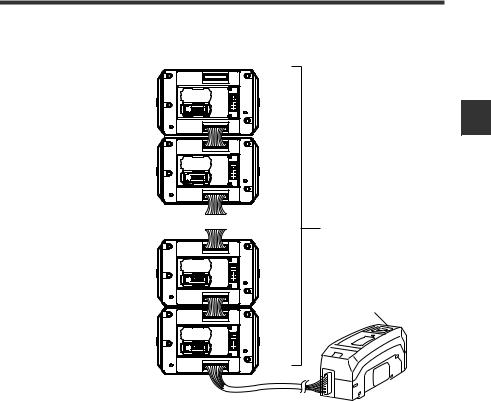
Several sensor amplifiers can be connected to the DL-EP1. ID numbers for data identification are assigned to each sensor amplifier.
The method for assigning ID numbers is as follows:
•ID numbers are assigned in order, starting from the sensor amplifier that is the main unit. (Optional numbers cannot be assigned.)
•0 is assigned as the ID number of the DL-EP1.
Point |
|
• You cannot change the ID numbers assigned to the sensor amplifiers. |
|
|
|
|
|
• In this manual, ID number 00 to ID number 08 are denoted as ID00 to |
|
|
ID08, respectively. |
|
|
|
Also for cyclic communication, output, current value, and external input are assigned one by one per ID number.
For DIN rail mount type
ID number 01 |
02 |
|
07 |
|
08 |
|
|
|
00 |
|
||||
|
|
|
|
|
|
|
|
|
|
|
|
|
|
|
|
|
|
|
|
|
|
|
|
|
|
|
|
|
|
|
|
|
|
|
|
|
|
|
|
|
|
|
|
|
|
|
|
|
|
|
|
|
|
|
|
|
|
|
|
|
|
|
|
|
|
|
|
|
|
|
|
|
|
|
|
|
|
|
|
|
|
|
|
|
|
|
|
|
|
|
|
|
|
|
|
|
|
|
|
|
|
|
|
|
|
|
|
|
|
|
|
|
|
|
|
|
|
|
|
|
|
|
|
|
|
|
|
|
|
|
|
|
|
|
|
|
|
|
|
|
|
|
|
|
|
|
|
|
|
Main |
Expansion |
Expansion |
Expansion |
unit |
unit |
unit |
unit |
2-6 |
- EtherNet/IP Compatible Network Unit DL-EP1 User’s Manual (IL) - |
2-2 Installation and Connection to Sensor Amplifiers
For panel mount type
ID number Sensor amplifier
01 |
|
Main |
|
unit |
|
|
|
|
02 |
|
Expansion |
|
|
unit |
... |
... |
Sensor amplifier |
|
|
|
07 |
|
Expansion |
|
unit |
|
|
|
DL-EP1 |
|
|
ID number 00 |
08 |
|
Expansion |
|
unit |
|
|
|
2
Configuration and Connection
- EtherNet/IP Compatible Network Unit DL-EP1 User’s Manual (IL) - |
2-7 |
2-3 Wiring
2
Configuration and Connection
The DL-EP1 uses the power supplied to sensor amplifiers, so there is no power cable wiring. This section describes the wiring of communication cables used by the DLEP1.
Connecting a communication cable
Use the following procedures to connect the DL-EP1 to the communication cable required for EtherNet/IP communication.
Usable cable
Usable cables depend on whether the system is configured with 10BASE-T or 100BASE-TX.
Structuring a 10BASE-T system
When the system is configured |
STP/UTP cable |
|
|
with 10BASE-T, use a Category |
|
3 or higher shielded twisted-pair |
|
(STP) cable or an unshielded |
|
twisted-pair (UTP) cable. |
|
Structuring a 100BASE-TX network
When the system (network) is configured with 100BASE-TX, use a Category 5 or higher STP or UTP cable. Do not use a Category 3 or Category 4 UTP cable.
Point |
|
• Use a STP/UTP straight cable when connecting the DL-EP1 to an |
|
|
|
|
|
Ethernet switch. |
|
|
• Use a STP/UTP cross cable when directly connecting the DL-EP1 to a |
|
|
PC. |
|
|
• Do not use the STP/UTP cross cable incorrectly because it is difficult to |
|
|
distinguish this cable from the STP/UTP straight cable in appearance. |
|
|
• When the system (Ethernet) is configured with a type (e.g., 10BASE-2 |
|
|
or 10BASE-5) other than 10BASE-T and 100BASE-TX, use an Ethernet |
|
|
switch with an AUI (MAU) connector or a BNC connector or use a media |
|
|
converter (10BASE5 → 10BASE-T or 10BASE2 → 10BASE-T). |
|
|
|
2-8 |
- EtherNet/IP Compatible Network Unit DL-EP1 User’s Manual (IL) - |

2-3 Wiring
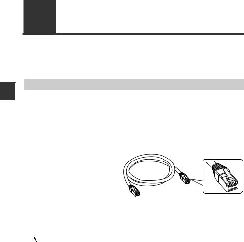
DL-EP1 connector port
The DL-EP1 connector port accepts an RJ-45 8-pole modular connector (ISO8877 compliant) used with 10BASE-T and 100BASE-TX and complies with the IEEE802.3 Standards.
Precautions for connecting a STP/UTP cable to the DL-EP1 connector port
Take care not to apply a load to the DL-EP1 connector port when connecting the STP/UTP cable to the DL-EP1.
The cable may be bent and used when installed. Bending the cable
at a sharp angle may cut the wires in the cable or the cable may be NOTICE disconnected during use. Install or lay the cable to be used with
attention to the recommended bending radius R of the cable.
Connecting the DL-EP1 to EtherNet/IP
The following describes how to connect the DL-EP1 to the RJ-45 connector.
1 |
Turn off the power supply. |
2 |
Connect one modular jack of the STP/UTP cable to the 10BASE-T/ |
100BASE port of the Ethernet switch to be used. |
Insert the modular jack until a "click" is heard. The modular jack and connector will lock.
 Point Keep the length of the STP/UTP cable to be used 100 m or less.
Carefully check the state of connector (port) on the Ethernet switch before connecting the DL-EP1. There are various Ethernet switches. Some Ethernet switches have a different shape connector (AUI connector or BNC connector, etc.) from the RJ-45, while some have connectors used to connect Ethernet switches together (cascade ports).
3 |
Connect the modular jack on the other end of the STP/UTP cable to the |
DL-EP1 connector port. |
Insert the jack until a "click" is heard. The modular jack and connector will lock.
2
Configuration and Connection
- EtherNet/IP Compatible Network Unit DL-EP1 User’s Manual (IL) - |
2-9 |

2-4 Configuring Communication with the DL-EP1
2
Configuration and Connection
This section describes settings for connecting the DL-EP1 to the EtherNet/IP system.
DL-EP1 Settings
The following describes how to set communication with the DL-EP1.
Setting the IP address
Set the IP address with the DL-EP1 wired and with the power supplied.
By default, the IP address is not set. However, you can use the BOOTP client function to set the IP address via Ethernet.
The following 2 methods are available for setting the IP address.
•Use the IP address setting tool (this tool can be downloaded from the Keyence web site http://www.keyence.com).
Refer to the following setting procedures or the  "IP Setting Tool User's Manual".
•Use an IP address setting tool from other sources.
Refer to the manuals provided by the respective sources.
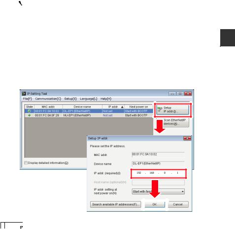
zUsing the IP address setting tool
Here briefly describes the procedures for setting the IP address with the IP address setting tool. For details on how to use the IP address setting tool, refer to
the  "IP Setting Tool User's Manual". You can view the "IP Setting Tool User's Manual" from [Help(H)] of "IP Setting Tool" as the PDF file.
1 |
Start the IP Setting Tool. |
Devices such as the DL-EP1 connected to the network and for which their IP |
addresses are not set will appear.
To display the devices for which their IP addresses are not set, click the [Scan EtherNet/IP devices (A)] button.
2-10 |
- EtherNet/IP Compatible Network Unit DL-EP1 User’s Manual (IL) - |
|
|
|
|
2-4 Configuring Communication with the DL-EP1 |
|
|
|
|
|
|
|
|
|
|
|
|
Point |
To display "Not Set" for the IP address, the network status indicator |
|
|
|
|
|
(NS) must be off (IP address not assigned). To unassign the IP |
|
|
|
|
address, hold down the Reset switch on the DL-EP1 for three |
|
|
|
|
seconds or longer. |
2 |
|
|
|
|
Select the device for which to set the IP address and click [Setup IP addr.(I)] to |
||||
display [Setup IP addr.]. |
||||
Compare the MAC address to be displayed with the front MAC address on the DL-EP1 and select the device for which to set the IP address.
Set an IP address which is not currently used in "IP addr.(required)(I)" and click the [OK] button.
2
Configuration and Connection
|
|
|
|
|
|
|
|
|
|
|
|
|
|
|
|
|
|
|
|
|
|
Reference |
Using the [Search available IP addresses (F)] button enables you to |
||||
|
||||||
|
search for open IP addresses. |
|||||
|
|
|||||
- EtherNet/IP Compatible Network Unit DL-EP1 User’s Manual (IL) - |
2-11 |
2-4 Configuring Communication with the DL-EP1
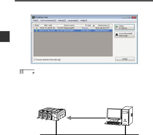
3 The IP address has now been set.
2
Configuration and Connection
Reference |
What is BOOTP? |
|
|
BOOTP is the abbreviation of BOOT strap Protocol. This protocol is used |
|||
|
|||
|
by the client device in the TCP/IP network to make the network settings |
||
|
assigned from the server. |
|
|
|
If there is a BOOTP server in the same network as the device running as |
||
|
the BOOTP client, an IP address is assigned to the device connected as |
||
|
the BOOTP client. |
|
|
|
BOOTP client |
BOOTP server |
|
|
IP address assignment |
|
|
Via Ethernet
Ethernet
2-12 |
- EtherNet/IP Compatible Network Unit DL-EP1 User’s Manual (IL) - |

2-5 Configuring Communication with the Scanner
This section describes scanner side configuration for connecting the DL-EP1 to the EtherNet/IP system.
When communicating with an Allen-Bradley scanner, also refer to the 
"Procedures for Communicating with an Allen-Bradley ControlLogix PLC" (Page 5-6).
Setting the scanner
Connecting the DL-EP1 to the EtherNet/IP scanner requires the following settings:
Setting the IP address
Set the IP address of the scanner.
Registering the device profile of the DL-EP1
Register the device profile of the adaptor (DL-EP1) to be connected using the scanner's setting software.
You can register the device profile manually or by reading the EDS (Electronic Data Sheet) file. You can download the EDS file of the DL-EP1 from the Keyence web site (http://www.keyence.com).
Configuring communication with the DL-EP1
The DL-EP1 uses EtherNet/IP cyclic communication or message communication to communicate with the scanner.
zCyclic communication (Implicit messaging)
This function sends and receives data at a set RPI (Requested Packet Interval). Selecting the communication method called "connection" and assigning the devices to be sent and received on the scanner side enables the DL-EP1 to communicate with the scanner without creating a ladder program.
zMessage communication (Explicit messaging)
This function is used to send and receive data which does not need to be timed. Use this function when changing the sensor amplifier settings or when performing EtherNet/IP communication with the scanner (e.g., Allen-Bradley SLC5/05 Series) that does not support cyclic communication.
This function uses a ladder program to create a message on the scanner side for communication.
For more information on setting each communication method, refer to the chapters titling "Communicating with...." of each sensor amplifier as well as the manuals enclosed with each scanner.
|
Reference |
This manual explains only the EtherNet/IP scanner functions and settings |
|
||
|
required for communication with the DL-EP1. For details on the functions |
|
|
|
|
|
|
and settings between the EtherNet/IP scanner and CPU unit, refer to the |
|
|
manuals enclosed with the scanner and CPU unit. |
2
Configuration and Connection
- EtherNet/IP Compatible Network Unit DL-EP1 User’s Manual (IL) - |
2-13 |

2-5 Configuring Communication with the Scanner
MEMO
2
Configuration and Connection
2-14 |
- EtherNet/IP Compatible Network Unit DL-EP1 User’s Manual (IL) - |
Loading...