


PX-10
Table of contents
 Loading...
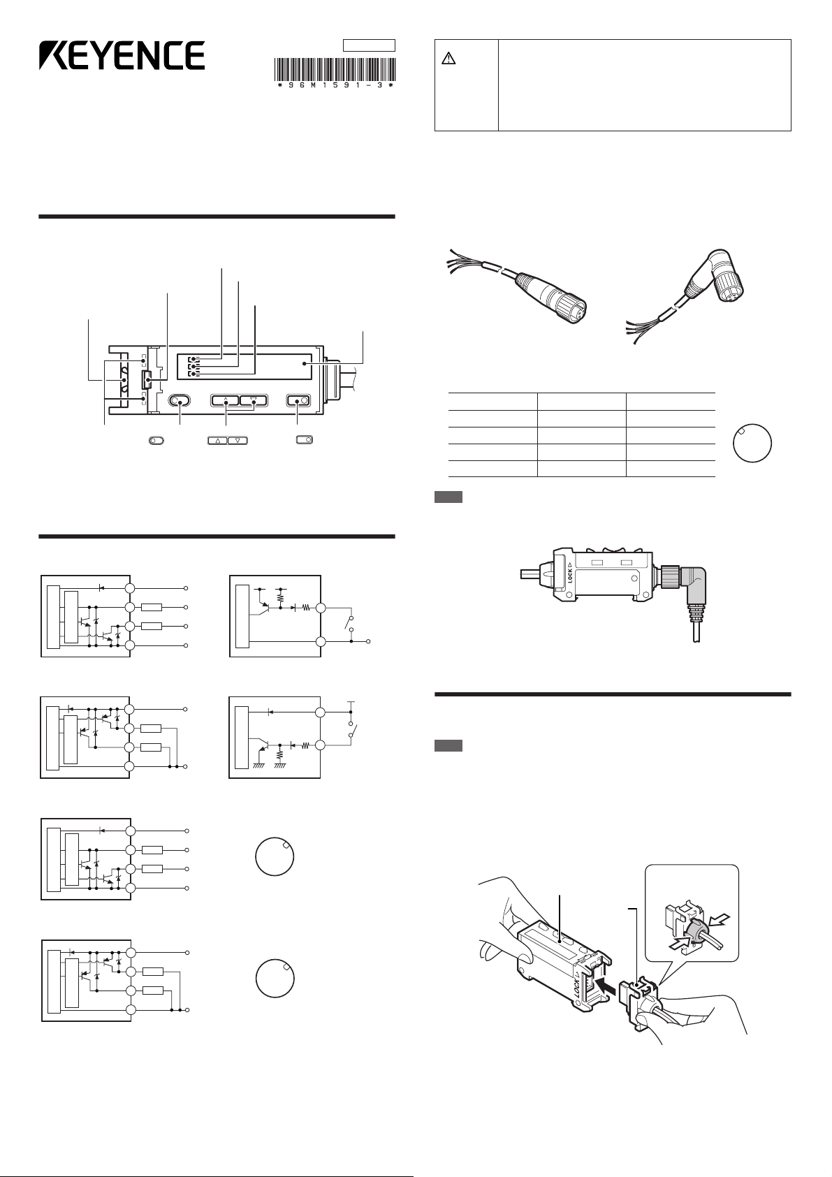
Heavy-duty Photoelectric Sensor
Connector
pin position
w
e
q
r
PX-10(P)/10C(P)
Instruction Manual
96M1591
Warning
• This product is used to detect targets. Do not apply the product to
safety circuits for human protection.
• This product is not of explosion-proof construction. Do not use the
products in places with flammable gas, liquid, or dust.
• This product is a sensor of DC power supply type. Do not apply
AC power. Application of the AC power may lead to explosion or
fire.
Part Names
Amplifier Unit
DSC indicator
Operation status indicator
Head release lever
Sensor head connector
receptacle
Head installation
holes
SET
SET
button
UP/DOWN
UP/DOWN
There are two types of amplifier units.
•
PX-10/10P (above): Uses a cable length of 2 m and can handle external input.
• PX-10C/10CP (connector type): Connects to the power source with a socket cable.
(detection output)
Operation status indicator
(alarm output)
Digital monitor
MODE
MODE
buttons
button
Input/Output Circuit
■PX-10 (NPN output)
Overcurrent
protection circuit
Light sensor circuit
Brown
Black (Detection output)
Load
White (Alarm output)
Load
Blue
12–24 V DC
5–40 V DC
5–40 V DC
0 V
3.3 V DC
(Short-circuit current
1 mA max.)
Main sensor circuit
Pink (input)
PLC, etc.
Blue
● Socket Cables for PX-10C/10CP (Optional)
■OP-75721 (cable length 2 m) ■OP-75722 (cable length 2 m)
■Relationship between connector pin numbers and cable core wires
Information in the following table is the same for OP-75721 and OP-75722.
Connector pin no. Wire casing color Connection
①
②
③
④
Note
When connecting the L-shaped cable (OP-75722) to the amplifier unit, face the
connector for the cable towards the amplifier unit in the direction shown in the following
diagram and lock it into place. Note that the connector portion cannot be reversed.
0 V
Brown 12 to 24 V DC
White Alarm output
Blue 0 V
Black
Detection output
■PX-10P (PNP output)
Overcurrent
protection circuit
Light sensor circuit
Brown
Black (Detection output)
Load
White (Alarm output)
Load
Blue
12–24 V DC
0 V
■PX-10C (connector type NPN output)
Overcurrent
protection circuit
Light sensor circuit
Pin q
Pin r (Detection output)
Load
Pin w (Alarm output)
Load
Pin e
12-24 V DC
5-40 V DC
5-40 V DC
0 V
■PX-10CP (connector type PNP output)
Overcurrent
protection circuit
Light sensor circuit
Pin q
Pin r (Detection output)
Load
Pin w (Alarm output)
Load
Pin e
12-24 V DC
0 V
Connector
pin position
w
e
q
r
Connector
pin position
w
e
q
r
(Short-circuit
current
2 mA max.)
Main sensor circuit
Brown
Pink (input)
12–24 V DC
PLC, etc.
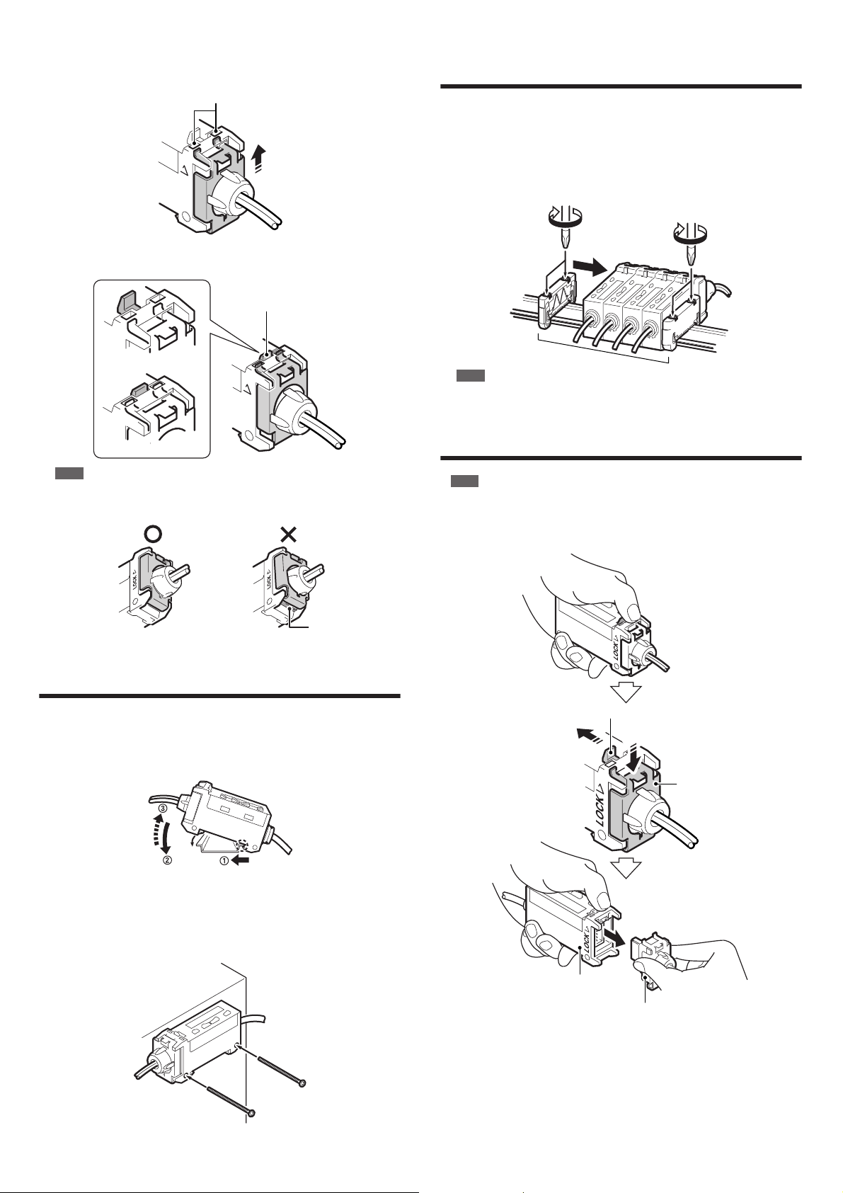
Precautions on Installation
●
Connecting the Sensor Head to the Amplifier Unit
Note
• The sensor is not guaranteed under the conditions of the warranty if the sensor head
is not connected correctly using the procedure described above.
• The sensor is not guaranteed under the conditions of the warranty if dust or dir t
attaches to the packing for the sensor.
• If the sensor head cannot be inser ted easily, fully remove any dirt or dust from the
amplifier unit and apply silicon grease to the opening.
1 Grasp the cap for the sensor head connector and insert the connector straight
in the direction shown in the diagram.
Amplifier unit
Sensor head
connector
Hold the cap by
the sides.
1
2
Insert the two upper tabs on the mounting fixture into the head installation hole
on the amplifier unit and pull the mounting fixture up in the direction shown in
the diagram. If the tabs do not slide into place easily, push on the bottom of the
mounting fixture.
Head installation hole
p
LOCK
Installation is complete when the head release lever locks into place as shown
in the following diagram.
Head release lever
Using Multiple Amplifier Units
(Interference Protection Function)
Installing multiple amplifier units (up to four) side by side on a DIN rail can protect
against interference.
Two end units (option item: OP-26751 (two units included)) are also required.
1
Install the sensor heads to the connected amplifier units.
Sandwich the amplifier units between the end units. Tighten the screws at the top
2
(two screws in two locations each) with a Phillips screwdriver to fix the end units.
Unlocked sensor head
LOCK
Locked sensor head
Note
Check that the lower tab on the mounting fixture for the connector fits into the
groove on the bottom of the amplifier unit. If the tab does not fit into the groove,
remove the sensor head and try connecting it again.
Tab is fitted in the groove.
Tab is not fitted in the groove.
Groove
Mounting the Amplifier Unit
Mounting on a DIN rail
■
1
Hook the tab located on the bottom of the amplifier unit to the DIN rail as
shown in the figure. While pushing the amplifier unit in the direction of arrow
, tilt it in the direction of arrow 2 .
End units
Note
End units must be used.
Removing the Sensor Head from the
Amplifier Unit
1
Note
Do not pull on the cable.
1
Grasp the amplifier unit. While pulling the head release lever in the direction of
arrow 1 , slide the mounting fixture for the connector in the direction of arrow
. Pull the connector from the amplifier unit in the direction of arrow 3 .
1
Head release lever
2
•
2
Mounting fixture
•
To dismount the sensor, raise the amplifier unit in the direction of arrow 3 while
2
pushing the amplifier unit in the direction of arrow 1 .
■
Mounting the amplifier unit sideways (Only for use with a single unit)
Mount the amplifier unit using M3 screws in the two locations as shown in the
diagram. Use a maximum torque of 0.6 N•m to tighten the screws.
3
Amplifier unit
Sensor head connector
●
Precautions for Installing the Sensor Head
Install the sensor head so that it can move at least 4 ° in any direction. This allows
beam-axis adjustment for the sensor head.
Use a mounting fixture especially made for beam-axis adjustment with an
elongated hole. Contact KEYENCE for more information about this item, which is
sold separately.
The sensor head cable in gray jacket is for the transmitter side and black jacket
for the receiver side.
2
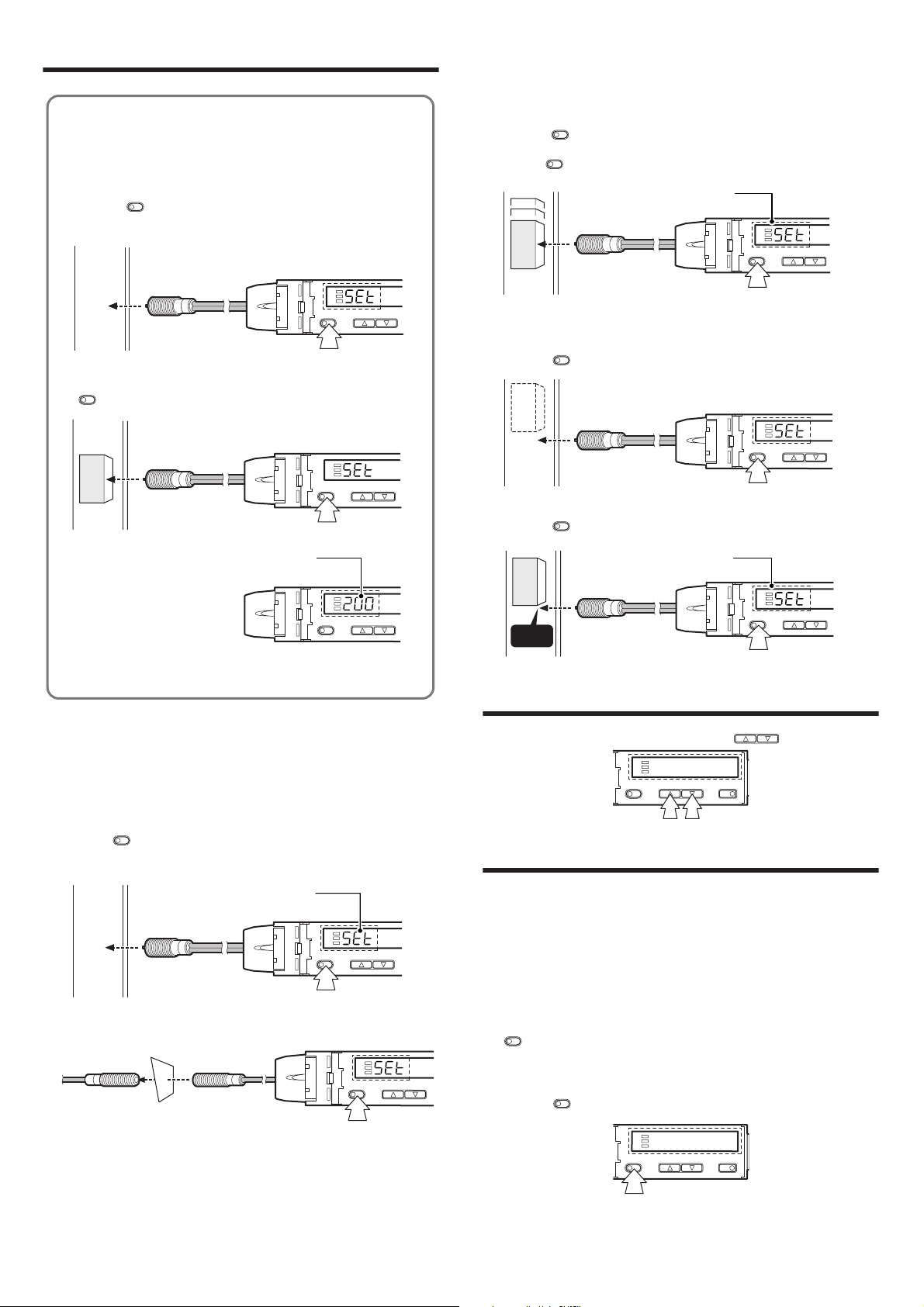
Setting a Sensitivity – Basic –
SET
UP/DOWN
SET
UP/DOWN
Workpiece
SET
UP/DOWN
3 seconds or longer
The set value will appear
when the settings are completed.
Workpiece
Edge
SET
UP/DOWN MODE
SET
UP/DOWN MODE
● Most Basic Sensitivity Settings
(2-point Calibration)
In this mode, the setting value used will be the mean value of two light
intensity values obtained through detection with and without a workpiece.
1 Press the button without any workpiece placed in front of the
sensor head.
SET
SET
UP/DOWN
2 Place a workpiece placed in front of the sensor head, and press the
SET
button.
SET
Workpiece
The set value will appear
when the settings are completed.
UP/DOWN
●
Detecting Moving Workpieces
(Full Auto Calibration)
In this mode, the set value will be set to the mean value of the maximum and
minimum values obtained within a certain period.
1
Press the button for at least three seconds while the target workpiece is
passing the sensing area of the sensor head.
While the button is pressed, the sensitivity of the sensor will be set
•
according to the incident values.
●
Positioning a Target (Positioning Calibration)
1
Press the button without any workpiece placed in front of the sensor
head.
Place a workpiece on the position where you want to perform positioning.
2
Press the button for at least three seconds. When the indication flashes,
release the button.
SET
SET
The set value will appear
when the settings are completed.
Workpiece
3 seconds or longer
SET
SET
SET
UP/DOWN
If the sensitivity difference is not large enough, "----" flashes for about two
seconds after the calibration is complete. The mean value of the two
detected values is still recorded.
●
Improving Performance against Dust and
Stains (Maximum Sensitivity Setting)
Set the sensitivity without a workpiece for a reflective type, and with a workpiece
for a thrubeam type. Set the sensitivity slightly higher than the amount of received
light at the setting time.
1
Press the button for at least three seconds in the state as shown in the
figure below. Release the button when "SET" flashes on the display.
Reflective
Thrubeam
SET
The set value will appear
when the settings are completed.
SET
3 seconds or longer
3 seconds or longer
UP/DOWN
SET
UP/DOWN
Fine-adjusting Sensitivity
The setting value can be changed by pressing the buttons.
UP/DOWN
Setting a Sensitivity – Advanced –
●
Setting Sensitivity with Signals from
External Devices (Page 6, No. 6)
By selecting "External calibration" in page 6, No. 6, the signal from an external
device can be used to set the sensitivity.
See "Using External Input" (page 4).
●
Percent (%) Calibration (Page 6, No. 3)
The sensitivity can be set as a percent (%) of received light intensity.
For example, when the percentage calibration target value is set to "-10P", pressing
SET
the button sets the value to 10% below the amount of received light.
When selecting the sensitivity setting method (page 6, No. 3), select percent
1
calibration, set the target value of calibration, and return to the normal display.
2
Press the button at the percentage for the desired reference for light
intensity.
SET
While percent calibration is selected, other calibrations (sensitivity setting) cannot
be used.
* External input (page 4) can still be used (PX-10/10P only).
3
Loading...