


 Loading...
96129E
Digital Laser Sensor
LV-N10 Series
User's Manual
Read this manual before use.
Keep this manual in a safe place for future reference.
Introduction
This manual describes the basic operations and hardware functions of the LV-N10 Series. Read this manual carefully to ensure safe performance and function of the LV-N10 Series. Keep this manual in a safe place for future reference.
Ensure that the end user of this product receives this manual.
 Symbols
The following symbols are used in this manual to alert you to matters concerning the prevention of injury and product damage.
Always read these sections.
It indicates a hazardous situation which, if not avoided, will result in
DANGER
death or serious injury.
It indicates a hazardous situation which, if not avoided, could result
WARNING
in death or serious injury.
Failure to follow the instructions may lead to minor or moderate
CAUTION
injury.
Failure to follow the instructions may lead to product damage as
NOTICE
well as property damage.

 Important Indicates cautions and limitations that must be followed during operation.
 Point Indicates additional information on proper operation.

 Reference Indicates tips for better understanding or useful information.
Indicates reference pages.

Safety Precautions
General Precautions
|
|
|
|
• |
This product is only intended to detect objects. Do not use this |
|
|
|
|
|
product for the purpose of protecting a human body or a part of |
|
|
|
|
|
the human body. |
|
|
|
|
• This product is not intended for use as an explosion-proof prod- |
|
|
WARNING |
|
|
uct. Do not use this product in a hazardous location and/or |
|
|
|
|
|
|
|
|
|
|
|
|
potentially explosive atmosphere. |
|
|
|
|
• |
This product uses DC power. Do not apply AC power. The prod- |
|
|
|
|
|
uct may explode or burn if an AC voltage is applied. |
|
|
|
|
|
|
|
|
|
|
|
|
|
|
|
|
• Do not wire the amplifier line along with power lines or high-ten- |
|
|
|
|
|
|
sion lines, as the sensor may malfunction or be damaged due to |
|
|
|
|
|
noise. |
|
|
|
|
• When using a commercially available switching regulator, |
|
|
|
|
|
|
ground the frame ground terminal and ground terminal. |
|
NOTICE |
|
|
• |
Do not use the LV-N10 Series outdoors, or in a place where |
|
|
|
|
||
|
|
|
|
|
extraneous light can enter the light-receiving element directly. |
|
|
|
|
• |
Due to individual dispersion characteristics and the difference |
|
|
|
|
|
in sensor head models, the maximum sensing distance or dis- |
|
|
|
|
|
played value may not be the same on all units. |
|
|
|
|
|
|
Safety Precautions on Laser Product
|
• This product uses a semiconductor laser for the light source. |
|
|
• |
Use of controls or adjustments or performance or procedures |
|
|
other than those specified herein may result in hazardous radia- |
|
|
tion exposure. |
|
• |
Follow the instructions mentioned in this manual. Otherwise, |
WARNING |
|
injury to the human body (eyes and skin) may result. |
|
|
|
|
Precautions on Class 1 laser products |
|
•Do not stare into the beam.
•Do not disassemble this product. Laser emission from this product is not automatically stopped when it is disassembled.
|
LV-NH32/NH35/NH37/ |
LV-S31/S41/S41L/S61/ |
|
|
Model |
NH42/NH62/NH100/ |
|
LV-S62/S63 |
|
|
S71/S72 |
|||
|
NH110/NH300 |
|
|
|
|
|
|
|
|
|
|
|
|
|
Wavelength |
660 nm |
|
655 nm |
660 nm |
|
|
|
|
|
Output |
310 øW |
|
290 øW |
|
|
|
|
|
|
FDA (CDRH) Part 1040.10* |
|
Class 1 laser product |
|
|
IEC 60825-1 |
|
Class 1 laser product |
|
|
|
|
|
|
|
96129E |
1 |

Safety Precautions
*The laser classification for FDA (CDRH) is implemented based on IEC60825-1 in accordance with the requirements of Laser Notice No.50.

 Reference Laser Transmission OFF input
When the laser transmission OFF input is set for external input, the laser transmission can be stopped by turning the external input ON (2 ms or longer). The transmission is stopped while the external input is ON. Once the external input is turned OFF, the laser transmission will resume within 20 ms.
Precautions on Regulations and Standards
UL Certification
This product is a UL/C-UL Listed product. (Contact KEYENCE for information on heads which support UL-certification.)
•UL File No. E301717
•Category NRKH, NRKH7
•Enclosure Type 1 (Based on UL50)
Be sure to consider the following requirements when using this product as a UL/C-UL Listed Product.
•Use a power supply with Class 2 output defined in NFPA70 (NEC: National Electrical Code).
•Power supply voltage is 10 - 30 VDC.
•Power supply/External input/ Control output shall be connected to a single Class 2 source only.
•Use with an over current protection device which is rated 30V or more and not more than 1A.
•Use this product under pollution degree 2.
CE Marking
Keyence Corporation has confirmed that this product complies with the essential requirements of the applicable EC Directive, based on the following specifications. Be sure to consider the following specifications when using this product in a member state of the European Union.
● EMC Directive (2004/108/EC)
• Applicable standard EMI : 60947-5-2, Class A EMS : 60947-5-2
When connecting with the NU-CL1, always install in a conductive enclosure (control panel, etc.), and wrap a ferrite core (E04SR401938 manufactured by Seiwa Electric Mfg. Co., Ltd.) one turn around the sensor head cable.
These specifications do not give any guarantee that the end-product with this product incorporated complies with the essential requirements of the EMC Directive. The manufacturer of the end-product is solely responsible for the compliance of the end-product itself according to the EMC Directive.
2 |
- Digital Laser Sensor LV-N10 Series User's Manual - |
|

Manual Organization
1

2

3

4

5

6

Before Using
Installation and
Connection
Basic Operation
Settings for Advanced Functions
Specifications
Appendix
Outlines the package contents and identifies part names and functions.
Provides procedures for installing sensor amplifiers and cables, as well as operating precautions.
Explains basic instructions for operating and setting the sensor amplifiers.
Describes settings for advanced functions of the LV-N10 Series.
Provides the specifications, circuit diagrams and dimensions of the LV-N10 Series.
Provides the troubleshooting instructions and initial settings (default values).
1
2
3
4
5
6
<Points for Using This Manual>
• When you "Forgot the operation methods" or "Want to find the operation procedures" J Go to pages 3-2, 4-2
• When you "Want to try out the LV-N10"
JGo to Chapters 2 and 3
•When you "Want to fully utilize the various functions"
JGo to Chapters 3 and 4
•When you "Want to know the meanings of terms used"
JGo to Chapter 6 (Index)
•When you "Want to troubleshoot the LV-N10"
JGo to Chapter 6 (Troubleshooting)
- Digital Laser Sensor LV-N10 Series User's Manual - |
3 |

Table of Contents
Safety Precautions............................................................................... |
1 |
General Precautions .......................................................................... |
1 |
Safety Precautions on Laser Product................................................. |
1 |
Precautions on Regulations and Standards ....................................... |
2 |
Manual Organization ........................................................................... |
3 |
Table of Contents ................................................................................. |
4 |
Chapter 1 Before Using
1-1 |
Checking the Package Contents.......................................................... |
1-2 |
|
Sensor Amplifier .............................................................................. |
1-2 |
|
Sensor Head ................................................................................... |
1-2 |
1-2 |
Part Names.......................................................................................... |
1-4 |
|
Sensor Amplifier .............................................................................. |
1-4 |
Chapter 2 Installation and Connection
2-1 |
Installing Sensor Amplifiers .................................................................. |
2-2 |
|
Mounting the Sensor Amplifier ........................................................ |
2-2 |
|
Wiring Diagrams for Sensor Amplifiers ........................................... |
2-4 |
2-2 |
Connecting the Sensor Amplifier to the Sensor Head.......................... |
2-5 |
|
Connecting the Sensor Amplifier to the Connector ......................... |
2-5 |
2-3 |
Mounting and Adjusting the Sensor Head ........................................... |
2-6 |
|
LV-NH32/NH35/NH37/NH42/NH62/S63.......................................... |
2-6 |
|
LV-NH100/NH110/NH300................................................................ |
2-6 |
|
LV-S31............................................................................................. |
2-7 |
|
LV-S41/S41L ................................................................................... |
2-8 |
|
LV-S62............................................................................................. |
2-8 |
|
LV-S71/S72 ................................................................................... |
2-10 |
Chapter 3 Basic Operation
3-1 |
Quick Reference .................................................................................. |
3-2 |
3-2 |
Switching Output.................................................................................. |
3-4 |
|
Output Switch (L-on/D-on) .............................................................. |
3-4 |
3-3 |
Adjusting the Sensitivity ....................................................................... |
3-5 |
|
List of Sensitivity Adjustment Methods............................................ |
3-5 |
|
Preset Function ............................................................................... |
3-6 |
|
Work-Preset Function ..................................................................... |
3-7 |
|
Maximum Sensitivity Preset Function ............................................. |
3-8 |
|
Full Auto Preset Function ................................................................ |
3-9 |
4 |
- Digital Laser Sensor LV-N10 Series User's Manual - |
|

|
|
|
Table of Contents |
|
|
|
|
|
|
|
|
Preset display mode (only when LV-N100/NH110/NH300 |
|
|
|
|
is connected)................................................................................. |
|
3-11 |
|
|
Two-point Calibration..................................................................... |
|
3-12 |
|
|
Maximum Sensitivity Calibration ................................................... |
3-13 |
|
|
|
Full Auto Calibration ...................................................................... |
|
3-14 |
|
|
Positioning Calibration................................................................... |
|
3-15 |
|
|
Other Calibration Methods ............................................................ |
3-16 |
|
|
3-4 Setting the Current Received Light Intensity to 0 (Zero Shift)............ |
3-17 |
||
|
|
Zero Shift Function........................................................................ |
|
3-17 |
|
|
Operating Principle of the Zero Shift Function .............................. |
3-17 |
|
|
3-5 Loading the Recommended Settings (Recipe Function) ................... |
3-19 |
||
|
|
Selecting Recipe ........................................................................... |
|
3-19 |
|
|
List of Recipes and Recommended Sensor Heads ...................... |
3-20 |
|
3-6 |
Initialization ........................................................................................ |
|
3-21 |
|
|
|
Initialization of Settings (Reset to Initial Values)............................ |
3-21 |
|
|
3-7 Locking in MEGA Mode ..................................................................... |
|
3-22 |
|
|
|
MEGA Mode Lock (1-Output Type Only)....................................... |
3-22 |
|
|
3-8 Disabling the Key Operation............................................................... |
|
3-23 |
|
|
|
Key Lock........................................................................................ |
|
3-23 |
|
|
Key Lock with PIN Number ........................................................... |
3-24 |
|
|
|
|
||
|
Chapter 4 Settings for Advanced Functions |
|
||
4-1 |
List of Settings ..................................................................................... |
|
4-2 |
|
4-2 |
Basic Settings ...................................................................................... |
|
4-4 |
|
|
|
Power Modes .................................................................................. |
|
4-4 |
|
|
Sensitivity Setting............................................................................ |
|
4-4 |
4-3 |
Detection Settings (Func) .................................................................... |
|
4-7 |
|
|
|
Output Timer ................................................................................... |
|
4-7 |
|
|
Detection Mode ............................................................................... |
|
4-8 |
|
|
External Input................................................................................ |
|
4-17 |
|
|
Parameter Save ............................................................................ |
|
4-19 |
|
|
Analog scaling (LV-N11MN only) ................................................... |
4-20 |
|
|
|
Analog scaling mode (LV-N11MN only) ......................................... |
4-21 |
|
4-4 |
Display Settings (diSP) ...................................................................... |
|
4-22 |
|
|
|
Display Reverse ............................................................................ |
|
4-22 |
|
|
Sub Display ................................................................................... |
|
4-22 |
|
|
Preset Saturation Function............................................................ |
4-27 |
|
4-5 |
System Settings (SYS) ...................................................................... |
|
4-29 |
|
|
|
Power Save ................................................................................... |
|
4-29 |
|
|
Display Gain .................................................................................. |
|
4-30 |
|
|
Interference Prevention ................................................................. |
|
4-31 |
|
|
Common Key-Operations Function ............................................... |
4-32 |
|
|
|
Sensitivity...................................................................................... |
|
4-32 |
4-6 |
2-output Settings ( |
) ............................................................ |
4-33 |
|
- Digital Laser Sensor LV-N10 Series User's Manual - |
5 |

Table of Contents
Detection Mode for Output2 .......................................................... |
4-33 |
Output Timer for Output2 .............................................................. |
4-37 |
4-7 Settings Save/Recall .......................................................................... |
4-38 |
Custom Save (Settings Save) ....................................................... |
4-38 |
User Reset (Settings Recall) ......................................................... |
4-39 |
Chapter 5 Specifications
5-1 |
Specifications....................................................................................... |
5-2 |
|
Sensor Head (1).............................................................................. |
5-2 |
|
Sensor Head (2).............................................................................. |
5-3 |
|
Sensor Amplifier .............................................................................. |
5-4 |
5-2 |
Circuit Diagrams .................................................................................. |
5-5 |
|
Cable Type Input/output Circuit Diagram......................................... |
5-5 |
|
M8 Connector Type Input/output Circuit Diagram ........................... |
5-5 |
|
Monitor Output Type Input/output Circuit Diagram .......................... |
5-5 |
5-3 |
Dimensions .......................................................................................... |
5-6 |
|
Sensor Amplifier .............................................................................. |
5-6 |
Chapter 6 Appendix
6-1 |
Troubleshooting.................................................................................... |
6-2 |
|
Frequently Asked Questions ........................................................... |
6-2 |
|
Error Displays and Corrective Actions............................................. |
6-4 |
6-2 Factory Default Setting (Default Value) List.......................................... |
6-5 |
|
6-3 |
List of Recipe Function Settings .......................................................... |
6-6 |
6-4 |
Restrictions on Each Detection Mode.................................................. |
6-8 |
|
Restrictions for Sensitivity Settings in Each Detection Mode.......... |
6-8 |
6-5 |
Index .................................................................................................. |
6-10 |
6 |
- Digital Laser Sensor LV-N10 Series User's Manual - |
|
|
|
|
|
Before Using |
1 |
|
|
This chapter outlines the package contents and identifies part |
|
||
|
|
||
names and functions. |
|
|
|
|
|
|
|
1-1 |
Checking the Package Contents ........................ |
1-2 |
1-2 |
Part Names ........................................................ |
1-4 |
- Digital Laser Sensor LV-N10 Series User's Manual - |
1-1 |

1
Using Before
1-1 Checking the Package Contents
Before using the LV-N10 Series, make sure that the following equipment and accessories are included in the package.
We have thoroughly inspected the package contents before shipment. However, in the event of missing, defective or broken items, contact your nearest KEYENCE office.
Sensor Amplifier

 LV-N10 Series
Sensor amplifier × 1 Instruction manual × 1
Sensor Head
LV-NH32* |
|
|
LV-NH35* |
|
|
|
|
Focus lock |
Plastic |
Mounting bracket set |
|
Mounting bracket set |
|
Transmitter |
screw |
|
|
|
|
|
|
|
driver |
Mounting bracket × 1 |
|
|
Mounting bracket × 1 |
|
|
|
|
|
||
|
|
|
Plate nut × 1 |
|
|
|
|
|
|
|
|
Plate nut × 1 |
|
|
|
|
M3 × 18 screw × 2 |
|
|
|
|
|
|
|
|
M3 × 18 screw × 2 |
|
Focus ring |
|
|
|
|
|
|
|
|
|
|
|
|
|
Receiver |
|
|
|
|
|
|
|
|
|
|
Transmitter/Receiver |
|
|
LV-NH37* |
|
|
LV-NH42* |
|
|
|
|
|
Mounting bracket set |
|
Slit |
|
|
|
|
|
(black and |
Mounting bracket set |
||
Transmitter |
|
|
|
Transmitter |
||
|
|
|
gray) |
|
||
|
|
|
|
|
||
|
|
|
Mounting bracket × 1 |
|
|
Mounting bracket × 1 |
|
|
|
Plate nut × 1 |
|
|
Plate nut × 1 |
|
|
|
M3 × 18 screw × 2 |
Receiver |
|
M3 × 18 screw × 2 |
|
|
|
|
|
|
|
Receiver |
|
|
|
|
|
|
LV-NH62* |
|
|
LV-NH100/NH110* |
|
||
|
Reflector |
|
Mounting bracket set |
Transmitter (T) |
|
Receiver (R) |
|
(R-6) × 1 |
(R-7) × 1 |
|
|
||
|
|
|
|
|
||
|
|
|
Mounting bracket × 1 |
|
|
|
Transmitter/ |
|
|
Plate nut × 1 |
|
|
|
Receiver |
|
|
M3 × 18 screw × 2 |
Gray cable |
Black cable |
|
|
|
|
|
|||
1-2 |
- Digital Laser Sensor LV-N10 Series User's Manual - |
|
|
|
1-1 Checking the Package Contents |
||||
LV-NH300* |
|
LV-S31 |
|
|
|
|
Transmitter (T) |
Receiver (R) |
Operation |
|
|
|
Mounting bracket set |
|
|
|
|
|
||
|
|
indicator (red) |
|
|
Transmitter |
|
|
|
|
|
|
||
|
|
|
|
|
|
|
|
FAR indicator |
|
|
|
Adjustment |
|
|
|
|
|
screwdriver |
||
|
(red) |
|
F |
|
Receiver |
|
|
|
J |
F |
|
||
|
JUST (center) |
N |
N |
|
|
|
|
|
|
|
|
|
|
|
indicator (green) |
|
|
|
|
|
|
|
NEAR |
|
|
Adjustment |
Mounting bracket × 1 |
|
Black cable |
indicator (red) |
|
|
||
Gray cable |
|
|
Plate nut × 1 |
|||
|
|
trimmer |
||||
|
|
|
|
|
M3 × 15 screw × 2 |
|
|
|
|
|
|
|
|

 LV-S41/S41L
Receiver


 Operation
indicator
(red)
Receiver Transmitter

 LV-S61
|
Mounting |
|
|
Transmitter |
bracket × 1 |
Mounting |
Reflector |
|
|||
|
bracket set |
(R-6) × 1 |
|
|
|
||
|
Operation |
Mounting bracket × 1 |
|
Operation |
Plate nut × 1 |
|
|
indicator |
indicator |
M2 × 12 screw × 2 |
|
(red) |
Transmitter/ |
(red) |
Receiver |
|
|
|
|
LV-S62 |
|
LV-S63 |
|
|
|
|
|
|
|
Mounting |
Reflector |
Transmitter/ |
Reflector (R-6L) × 1 |
|
|
bracket set |
(R-9) × 1 |
|
|
|
|
||
Receiver |
|
|
|
|
|
|
|
Operation |
L-mounting bracket × 1 |
||
Spot selection switch |
|
|
|||
|
Transmitter/ |
indicator |
M4 nut × 3 |
|
|
|
|
(red) |
M4 × 30 screw × 3 |
|
|
Operation indicator |
|
Receiver |
|
|
|
(red) |
|
|
|
|
|
LV-S71/S72 |
|
|
|
|
|
|
Operation indicator (red) |
Mounting bracket × 2 |
|
Beam axis |
|
|
|
|
|
||
alignment plate × 1
|
|
Nut × 4 |
|
|
Spacer × 2 |
|
|
Washer × 2 |
Transmitter |
Receiver |
Œ30 |
|
||
|
|
*There is a bar LED monitor on the sensor head LV-NH32/NH35/NH37/NH42/ NH62/NH100/NH110/NH300.
Bar LED Monitor (Sequenced with sensor amplifier)
Stable light |
|
|
+10% |
Turns ON according to |
reception |
|
|
and higher |
the received light intensity |
Setting |
|
|
|
with respect to the set |
|
|
|
value. |
|
value |
|
|
|
The stability level of the |
|
|
|
||
Stable |
|
|
-10% |
|
blocking |
|
|
and higher |
current detection is |
|
|
|
|
displayed. |
If stable light reception or stable blocking is disabled because of the surrounding environment or changes in the workpiece, readjust the sensitivity.
Bar LED monitor excess gain display
With the 2-output type sensor amplifier, if the channel switch is set to 1, the output 1 excess gain is shown. If set to 2, the output 2 excess gain is shown.
1
Using Before
- Digital Laser Sensor LV-N10 Series User's Manual - |
1-3 |

1
Using Before
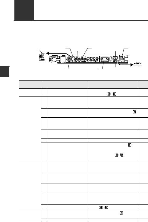
1-2 Part Names
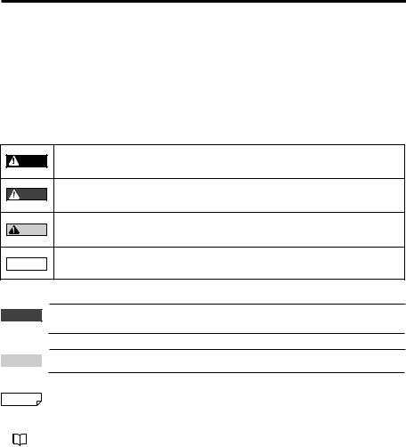
Sensor Amplifier
Display/control unit |
Expansion connector*1 |
Hold lock lever |
Expansion connector*1*2 |
Hook |
|
|
Dust cover |
M8 connector (LV-N11C /N12C )
Connection cable (LV-N11 /N12 /N11MN)
w/o cable (LV-N10)
*1 When shipped from the factory, the expansion cover is installed.
*2 This is not installed on the main unit (LV-N11N/N11P/N11CN/N11CP/N11MN).
1-4 |
- Digital Laser Sensor LV-N10 Series User's Manual - |
|
1-2 Part Names
Display/control unit
(1)-2 |
(1)-1(10) |
(9) |
|
(8) (7) |
|||||
|
|
|
|
|
|
|
|
|
|
|
|
|
|
|
|
|
|
|
|
|
|
|
|
|
|
|
|
|
|
|
|
|
|
|
|
|
|
|
|
|
|
|
|
|
|
|
|
|
|
|
|
|
|
|
|
|
|
|
|
(2) |
(3) |
(4) |
(5) |
(6)-1* |
(6)-2* |
* Not available for the LV-N10.
|
Item |
|
|
Description |
||
(1)-1 |
Operation indicator |
Indicates the current output (detection) status of chan- |
||||
|
(2-output type) |
nels 1 and 2 separately. |
|
|||
(1)-2 |
Operation indicator |
Indicates the current output (detection) status. |
||||
(1-output type) |
||||||
|
|
|
|
|||
(2) |
[SET] button |
Used when setting sensitivity, etc. |
||||
|
"Adjusting the Sensitivity" (page 3-5) |
|||||
|
|
|
||||
|
|
|
|
|
|
|
(3) |
Setting value |
Displays a setting value or advanced setting item in this |
||||
(Displayed in green) |
area of 7-segment green indicators. |
|||||
|
|
|
|
|||
|
Current value |
Displays the current value (received light intensity), or a |
||||
(4) |
selection from advanced settings, in this area of 7-seg- |
|||||
(Displayed in red) |
||||||
|
|
ment red indicators. |
|
|||
(5) |
Manual button |
Used to adjust the setting value or select an option. |
||||
|
Channel select |
Toggles between channels 1 and 2 for configuring the |
||||
(6)-1 |
switch |
received light intensity display or sensitivity setting. |
||||
|
(2-output type) |
|
"2-output Settings ( |
)" (page 4-33) |
||
|
|
|||||
|
|
|
|
|
|
|
|
|
Changes power modes. |
|
|||
|
Power select switch |
SEL: Allows you to set a power mode using the "Chang- |
||||
(6)-2 |
(1-output type) |
|
|
ing Power Modes" function of basic setup. |
||
M: |
Fixes the power mode to "MEGA mode". |
|||||
|
|
|||||
|
|
|
"Locking in MEGA Mode" (page 3-22) |
|||
|
|
|
||||
|
|
|
|
|
|
|
(7) |
[PRESET] button |
Used for presetting or setting values or parameters. |
||||
|
"Adjusting the Sensitivity" (page 3-5) |
|||||
|
|
|
||||
|
|
|
|
|
|
|
(8) |
[MODE] button |
Used |
for toggling L-on/D-on, |
proceeding to advanced |
||
settings, or confirming selections. |
||||||
|
|
|||||
|
|
|
|
|||
|
|
Lights when a DATUM mode is in effect. |
||||
(9) |
DTM indicator |
|
"DATUM1 mode" (page 4-9) |
|||
|
||||||
|
|
|
"DATUM2 mode" (page 4-11) |
|||
|
|
|
||||
|
|
|
|
|
|
|
(10) |
PST indicator |
Lights when preset value is set. |
||||
|
"Adjusting the Sensitivity" (page 3-5) |
|||||
|
|
|
||||
|
|
|
|
|
|
|
1
Using Before
- Digital Laser Sensor LV-N10 Series User's Manual - |
1-5 |

1-2 Part Names
MEMO
1
Using Before
1-6 |
- Digital Laser Sensor LV-N10 Series User's Manual - |
|
|
|
|
|
Installation and Connection |
2 |
|
|
This chapter provides procedures for installing sensor amplifiers and |
|
||
|
|
||
cables, as well as operating precautions. |
|
|
|
|
|
|
|
2-1 |
Installing Sensor Amplifiers................................. |
2-2 |
2-2 |
Connecting the Sensor Amplifier to the Sensor Head..... |
2-5 |
2-3 |
Mounting and Adjusting the Sensor Head.......... |
2-6 |
- Digital Laser Sensor LV-N10 Series User's Manual - |
2-1 |
2
Connection and Installation
2-1 Installing Sensor Amplifiers
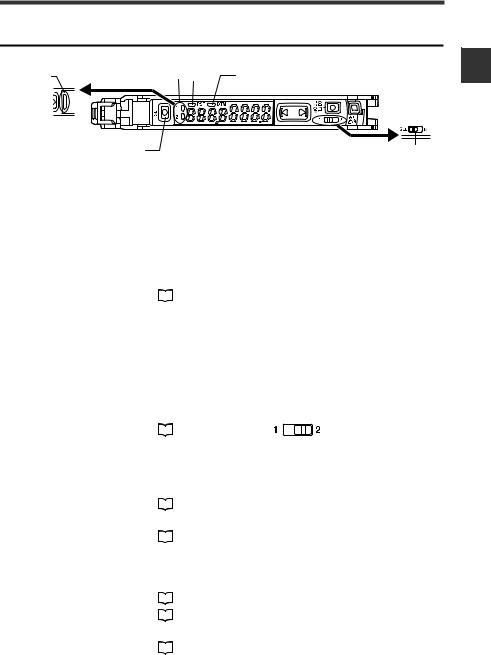
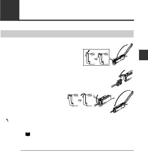
Mounting the Sensor Amplifier
Mounting on a DIN rail
1 |
Align the claw at the bottom of the main body |
with the DIN rail, as shown on the right. |
|
|
While pushing the main body in the direction |
|
of the arrow (1), push down in the direction of |
|
arrow (2). |
2 |
To release the amplifier, raise the amplifier |
body in the direction of arrow (3) while push- |
ing in the direction of arrow (1).
(3)
(2)
(1)
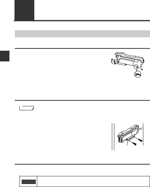
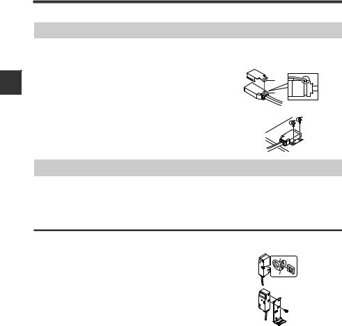
Installation on a wall
 Reference This method applies only when using the main unit independently. If the main unit is connected with an expansion unit(s), use the method of mount-
|
ing on a DIN rail. |
|
1 |
Mount the amplifier on the amplifier mount- |
|
ing bracket (OP-73880, sold separately), |
|
|
|
using the same manner as "Mounting on a |
|
|
DIN rail". |
|
2 |
Secure the unit with two M3 screws as |
OP-73880 |
shown in the illustration. |
|
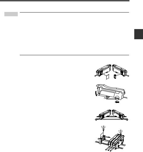
Connecting multiple amplifiers
Up to 16 expansion units can be connected to 1 main unit. Note, however, that the 2- output type is considered as 2 expansion units.
Mount on DIN rail and install on metal surface when connecting 
 WARNING multiple amplifiers or mounting main units together.
2-2 |
- Digital Laser Sensor LV-N10 Series User's Manual - |
|
2-1 Installing Sensor Amplifiers
 Point • Contact your nearest KEYENCE office when connecting a unit other than the N-bus (KEYENCE’s wire-saving system) compatible sensor amplifier, including LV-N10 Series, or the NU Series communication module.
• Turn the power off before connecting multiple expansion units.
•Do not touch the expansion connector with your bare hands.
•When using the LV-N10 Series as a main unit, use the products within the expansion unit’s power voltage range if the power voltage range of the expansion unit is narrower than the LV-N10 Series.
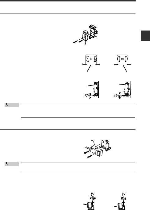
1 |
Remove the protection covers from the main unit |
and expansion unit(s). |
|
2 |
Mount the main unit and expansion unit(s) on the |
DIN rail. |
|
|
(2) |
3 |
(1) |
Slide the main unit and expansion unit(s) together. |
|
Engage the 2 claws of the expansion unit with the |
|
|
recesses on the main unit side until you hear/ feel |
4 |
a click. |
Attach the separately sold end units (OP-26751: a |
|
set of 2 units) to the DIN rail in the same manner |
|
|
as step (2). |
5 |
Secure the amplifiers between the end units. |
Tighten the screws at the top (2 screws × 2 units) |
with a Phillips screwdriver to fix the end units.
OP-26751 (a set of 2 units)
2
Connection and Installation
- Digital Laser Sensor LV-N10 Series User's Manual - |
2-3 |

2
Connection and Installation
2-1 Installing Sensor Amplifiers
Wiring Diagrams for Sensor Amplifiers
Point |
|
• |
Be sure to turn off the power before wiring. |
|
|
• |
Insulate each input or output cable that will not be used. |
|
|
|
|
Cable type (LV-N11 /N12 )
Brown*
10 to 30 VDC
Blue*
Black
Output 1
White
Output 2
Pink
External input
* LV-N11N/N11P only
M8 connector type (LV-N11C /N12C )
(1)*
|
(3)* |
10 to 30 VDC |
|
|
|
|
|
|
|
|
(2) |
|
External input |
|
|
|
|
||
|
(4) |
|
Output |
|
|
|
|
|
|
|
* LV-N11CN/N11CP only |
|
||
OP-73864 |
|
4 |
2 |
|
(Cable length: 2 m) |
|
3 |
1 |
|
|
|
|
|
|
OP-73865 |
|
|
|
|
(Cable length: 10 m) |
|
Pin and wire color table |
||
|
|
Connected |
Wire color |
|
|
|
pin No. |
||
|
|
|
||
|
|
|
1 |
Brown |
|
|
|
2 |
White |
|
|
|
3 |
Blue |
|
|
|
4 |
Black |
Monitor output type (LV-N11MN)
Brown
 10 to 30 VDC
Blue
Black
Output
Orange*
Monitor output (1 to 5 V)
Pink
External input
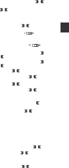
*Connect to a device having an input impedance of 10kΩ or more.

 Reference Refer to
  "Circuit Diagrams" (page 5-5) for the input/output circuit diagrams.
2-4 |
- Digital Laser Sensor LV-N10 Series User's Manual - |
|
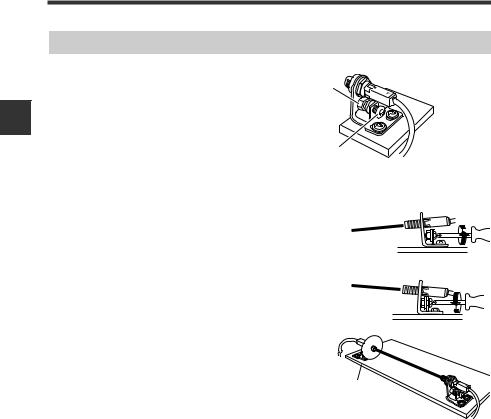
2-2 Connecting the Sensor Amplifier to the Sensor Head
Connecting the Sensor Amplifier to the Connector
1 |
Open the dust cover, and move the hold |
|
lock lever down. |
||
2 |
Lift the hook up, and insert the connec- |
|
tor completely. |
||
3 |
Lower the hook to the position |
|
shown in the drawing, and pull |
|
|
|
up the hold lock lever. |
|
|
|
|
Point |
|
• When connecting to a different sensor head model, the settings for |
|
|
the previously connected model will be saved. |
|
|
Either reconfirm or initialize the settings. |
 "Initialization of Settings (Reset to Initial Values)" (page 3-21)
•When shortening the sensor head cable, follow the instructions given in the "Sensor Head Connector Assembly Procedures" included with the sensor head.
2
Connection and Installation
- Digital Laser Sensor LV-N10 Series User's Manual - |
2-5 |

2
Connection and Installation
2-3 Mounting and Adjusting the Sensor Head
LV-NH32/NH35/NH37/NH42/NH62/S63
Use the included mounting bracket.
The tightening torques are shown below.
LV-NH32/NH35/NH37/NH42/NH62: 0.3 N·m
LV-S63: 0.6 N·m
LV-NH32 spot diameter adjustment
Turn the focus ring to adjust the size of the spot diameter.
After adjusting, tighten fix the focus lock screw.
LV-NH100/NH110/NH300
Using the following optional brackets to mount the unit.
LV-NH100/NH100: Vertical mounting bracket (LV-B101) or horizontal mounting bracket (LV-B102) LV-NH300: Vertical mounting bracket (LV-B301) or horizontal mounting bracket (LV-B302)
Vertical mounting bracket (LV-B101/LV-B301)
Included: Mounting bracket 2 pcs., plate nut 2 pcs., M3 ×  18 screws 4 pcs.
1 Mount as shown on the right.
Horizontal mounting bracket (LV-B102/LV-B302)
Included: Mounting bracket 2 sets, plate nut 2 pcs., M3 ×  18 screws 4 pcs.
1 Mount as shown on the right.
Insert the plate nut* between the sensor section and mounting bracket.
*When using LV-NH100/NH110, the long plate nut is used for the transmitter, and the short plate nut for the receiver.
When using LV-NH300, the long plate nut is used for the receiver, and the short plate nut for the transmitter.
2-6 |
- Digital Laser Sensor LV-N10 Series User's Manual - |
|
2-3 Mounting and Adjusting the Sensor Head
2 |
Adjust the beam axis. |
(a) |
|
||
|
|
(1)Adjust the beam axis upward by tightening the
(a) screw, and downward by loosening the screw. Fix the angle setting with the (b) nut.
(2)Adjust the horizontal angle by loosening the fixing section (c).
(b) |
(c) |
LV-S31
1 |
Mount using the Included mounting |
|
|
bracket. |
JF |
F |
|
|
|
N |
N |
2 |
Place a workpiece at the position to be |
|
|
set as the detection center. |
|
|
3 |
Turn the trimmer with the Included adjustment |
|
|
||
screwdriver, and adjust so that the (2) JUS indi- |
F |
F |
|||
|
cator lights in green. |
N |
N |
||
|
|
|
|
J |
|
(1) |
|
|
|
F |
F |
F |
F |
If the (1) FAR indicator is ON, turn the trimmer |
J |
|
|
(2) |
J |
|
N |
N |
|
N |
N |
clockwise until (2) turns ON. |
|||
(3) |
|
|
|
|
|
|
|
If the (3) NEAR indicator is ON, turn the trimmer |
|
|
|
|
|
|
|
|
|
Trimmer |
|
counterclockwise until (2) turns ON. |
|
|
|
|
|
|
|
||
When the LV-S31 is connected, the workpiece position is numerically displayed on the main screen (red display) using the center position as [5000]. If adjust the workpiece position precisely, set the display of sensor amplifier approximate [5000]. The display changes as follows according to the workpiece position.
|
|
Display |
Meaning |
Near |
---- |
Out of detection range |
|
|
|
|
|
|
|
nEAr |
The detector is nearer to the sensor side than numerical dis- |
|
|
||
|
|
play range |
|
|
|
|
|
|
|
|
|
|
|
5000 |
Centering on 5000, the value increases as the workpiece dis- |
|
|
tance increases from the sensor |
|
|
|
|
|
|
|
|
|
|
|
FAr |
The workpiece is farther from the sensor than the numerical |
|
|
display range |
|
|
|
|
|
|
|
|
|
Far |
---- |
Out of detection range |
|
|
|
|
|
2
Connection and Installation
- Digital Laser Sensor LV-N10 Series User's Manual - |
2-7 |
2
Connection and Installation
2-3 Mounting and Adjusting the Sensor Head
LV-S41/S41L
Always use the included mounting bracket.
1 |
Attach the mounting bracket as shown on |
|
the right. |
A |
|
|
Match section A of the fitting onto section |
B |
|
B of the sensor head |
|
2 |
Attach onto a flat surface with M3 screws as |
|
shown on the right. |
|
(M3 screws are not included.)
LV-S62
Mount with the optional L-mounting bracket (OP-84350), back surface mounting bracket (OP-84349) or horizontal mounting bracket (OP-84351).
L-mounting bracket (optional: OP-84350)
Included: Mounting bracket ×1 / plate nut × 1 / M3 ×  7.3 screw × 1
1 |
Insert the plate nut into the mounting slot on the |
back of the head. |
|
2 |
Align the protrusion with the hole on the top of |
bracket, and attach with the included mounting |
screws.
The tightening torque is
0.5 N·m or less.
2-8 |
- Digital Laser Sensor LV-N10 Series User's Manual - |
|
2-3 Mounting and Adjusting the Sensor Head
Back surface mounting bracket (optional: OP-84349)
Included: Mounting bracket × 1 / M3 ×  18 screw × 2
1 |
Attach as shown on the right. |
|
The tightening torque is |
2 |
0.5 N·m or less. |
Adjust the beam axis. |
(1)The beam axis angle can be adjusted sideways by loosening screws (a), (b), and (c) and moving the bracket left and right. Always tighten screw (b) first.
(2)The beam axis can be adjusted in the downward direction by tightening the bottom screw as shown with the arrow. It can be adjusted in the upward direction by loosening the same screw.
a
(c)
b
To move the beam axis downward
 (c)
(c)
a b
b
To move the beam axis upward
Point |
Always adjust the beam axis in the order of steps (1) and (2). |
|
The screws shown in (1) could be damaged if these steps are reversed.
Horizontal mounting bracket (optional: OP-84351)
Included: Mounting bracket × 1 / M3 ×  18 screw × 2
1 |
Attach as shown on the right. |
Spot selection |
|
|
|
switch |
|
|
|
|
The tightening torque is |
|
|
|
0.5 N·m or less. |
|
Point When mounting the sensor head in the direction opposite of that |
||
|
shown above, set the spot selection switch before mounting. |
||
2 Adjust the beam axis. |
|
|
|
|
The beam axis can be adjusted in the |
To move the beam axis |
To move the beam axis |
|
|
upward |
downward |
upward direction by tightening the screw as shown with the arrow. It can be adjusted in the downward direction by loosening the same screw.
2
Connection and Installation
- Digital Laser Sensor LV-N10 Series User's Manual - |
2-9 |
2
Connection and Installation
2-3 Mounting and Adjusting the Sensor Head
LV-S71/S72
1 |
Attach so that the side on which |
the T (transmitter) and R (receiver) |
|
|
are printed faces upward. The |
|
operation indicator lights are on |
|
the printed side. |
2 |
Adjust the beam axis. |
Fixing nut
Axis beam adjustment screw
The tightening torque is 1.2 N·m or less.
The beam axis can be adjusted in the downward To move the beam axis downward direction by tightening the screw as shown with
the arrow. It can be adjusted in the upward direction by loosening the same screw.
Adjust so that the beam spot is centered on the receiver.
When adjusting, attach the beam axis alignment plate, included with the sensor head, onto the end of the receiver to aid in alignment.
Remove the beam axis alignment plate cap when finished adjusting.
To move the beam axis upward
Beam axis alignment plate
2-10 |
- Digital Laser Sensor LV-N10 Series User's Manual - |
|
|
|
|
|
Basic Operation |
3 |
|
|
This chapter explains basic instructions for operating and setting the |
|
||
|
|
||
sensor amplifier. |
|
|
|
|
|
|
|
3-1 |
Quick Reference................................................. |
3-2 |
3-2 |
Switching Output ................................................ |
3-4 |
3-3 |
Adjusting the Sensitivity............................................... |
3-5 |
3-4 |
Setting the Current Received Light Intensity to 0 (Zero Shift) .. |
3-17 |
3-5 |
Loading the Recommended Settings (Recipe Function) ... |
3-19 |
3-6 |
Initialization....................................................... |
3-21 |
3-7 |
Locking in MEGA Mode.................................... |
3-22 |
3-8 |
Disabling the Key Operation ............................. |
3-23 |
- Digital Laser Sensor LV-N10 Series User's Manual - |
3-1 |
3
Operation Basic
3-1 Quick Reference
The main setting operations are explained according to purpose. Refer to Chapter 4 for information on advanced function settings and explanations not given below.
Operation |
Operation indicator |
PST |
DTM |
|
|
[MODE] |
|
[PRESET] |
||||
indicator |
|
(2-output type) |
indicator |
indicator |
|
|
button |
|
button |
|
||
(1-output type) |
|
|
|
|
|
|
|
|
|
|
|
|
|
|
[SET] button |
Manual button |
|
Channel select |
|
Power select |
|||||
|
|
|
|
|
|
switch |
|
|
switch |
|
||
|
|
|
|
|
|
(2-output type) |
|
(1-output type) |
||||
Purpose |
|
Description |
|
Operation procedures |
|
Reference |
||||||
|
|
|
page |
|||||||||
|
|
|
|
|
|
|
|
|
|
|
||
Changing the |
1 |
Change the output. (L-on/D-on) |
1. Press the [MODE] button. |
|
|
3-4 |
||||||
|
|
|
|
|
|
|
||||||
output |
2. Switch with the |
( |
) button. |
|
||||||||
|
|
|
|
|
||||||||
|
|
|
|
Reflective model: Press the [PRESET] button |
|
|||||||
|
2 |
Set the current received light intensity |
when a workpiece is present. Thrubeam/Retro- |
3-6 |
||||||||
|
to "100.0". (Preset) |
|
reflective model: Press the [PRESET] button |
|||||||||
|
|
|
|
|||||||||
|
|
|
|
when no workpiece is present. |
|
|
|
|||||
|
|
When preset is valid, register the |
After step 2, press the [PRESET] button + |
|
||||||||
|
3 |
received light intensity ".0". |
3-7 |
|||||||||
|
button in the state to be set as ".0". |
|
||||||||||
|
|
(Work-preset) |
|
|
|
|||||||
|
|
Set the received light intensity slightly |
While the PST indicator is OFF, press and hold |
|
||||||||
Adjusting the |
4 |
higher than when the setting was |
the [PRESET] button. Reflective model: When |
3-8 |
||||||||
made, to "100.0". (Maximum sensitiv- |
no workpiece is present. Thrubeam/Retro- |
|||||||||||
sensitivity and |
|
|
||||||||||
|
ity preset) |
|
reflective model: When a workpiece is present. |
|
||||||||
integrating the |
|
|
|
|||||||||
|
|
|
|
|
|
|
|
|
|
|
||
display to "100.0" |
|
Automatically register "100.0" and ".0" |
Press and hold the [PRESET] button while the |
|
||||||||
and ".0" |
5 |
when workpiece passes by. (Full Auto |
3-9 |
|||||||||
PST indicator is OFF. |
|
|
|
|||||||||
|
|
preset) |
|
|
|
|
|
|||||
|
|
|
|
|
|
|
|
|
|
|
||
|
6 |
Cancel the various preset functions. |
Press and hold the [PRESET] button. |
|
3-6 |
|||||||
|
|
Set the display for preset execution to |
1. Press and hold the [MODE] button, |
but- |
|
|||||||
|
|
ton and [SET] button simultaneously. |
|
|
||||||||
|
|
"1000" (LV-NH100/NH110) or "3000" |
|
|
||||||||
|
7 |
2. Press the [MODE] button. |
|
|
3-11 |
|||||||
|
(LV-NH300). (Preset area display |
|
|
|||||||||
|
|
3. Select "Pr-d ArEA" with |
( |
) button, and |
|
|||||||
|
|
mode) |
|
|
||||||||
|
|
|
|
press and hold the [MODE] button. |
|
|
||||||
|
|
Set the setting value at the midpoint |
1. Press the [SET] button once when a work- |
|
||||||||
|
8 |
between the received light intensity |
piece is present. |
|
|
|
|
|
3-12 |
|||
|
values when a workpiece is present |
2. Press the [SET] button once when no work- |
||||||||||
|
|
|
||||||||||
|
|
and absent. (2-point calibration) |
piece is present. |
|
|
|
|
|
|
|||
|
|
Set the setting value slightly higher |
Reflective model: Press and hold the [SET] but- |
|
||||||||
|
9 |
than the received light intensity value |
ton when no workpiece is present. Thrubeam/ |
3-13 |
||||||||
|
at which the setting was made. (Maxi- |
Retro-reflective model: Press and hold the |
||||||||||
|
|
|
||||||||||
Adjusting the |
|
mum sensitivity calibration) |
[SET] button when a workpiece is present. |
|
||||||||
|
Set the setting value automatically |
|
|
|
|
|
|
|
|
|||
sensitivity |
|
Press and hold the [SET] button while the work- |
|
|||||||||
10 |
when a workpiece is passing through. |
3-14 |
||||||||||
|
piece passes through. |
|
|
|
||||||||
|
|
(Full auto calibration) |
|
|
|
|
|
|||||
|
|
|
|
|
|
|
|
|
|
|
||
|
|
Set the setting value to the base point |
1. Press the [SET] button once when no work- |
|
||||||||
|
|
piece is present. |
|
|
|
|
|
|
||||
|
11 |
where the workpiece is positioned. |
|
|
|
|
|
3-15 |
||||
|
2. Press and hold the [SET] button at the posi- |
|||||||||||
|
|
(Positioning calibration) |
|
|
||||||||
|
|
|
tioning point. |
|
|
|
|
|
|
|
||
|
|
|
|
|
|
|
|
|
|
|
||
|
12 |
Finely adjust the setting value directly. |
Press the |
( |
|
) button. |
|
|
1-5 |
|||
Shifting the |
13 |
Set the current display to ."0". (Zero |
Press the [PRESET] button + |
button when |
3-17 |
|||||||
received light |
shift) |
|
the PST indicator is OFF. |
|
|
|
||||||
|
|
|
|
|
|
|||||||
intensity to ."0" |
14 |
Cancel the zero shift function. |
Press and hold the [PRESET] button. |
|
3-17 |
|||||||
|
|
|||||||||||
3-2 |
- Digital Laser Sensor LV-N10 Series User's Manual - |
|
|
|
|
|
|
|
|
|
3-1 |
Quick Reference |
||||
|
|
|
|
|
|
|
|
|
|
|
|
|
|
|
|
|
|
|
|
|
|
|
|
|
|
|
|
|
Purpose |
|
Description |
|
Operation procedures |
|
|
Reference |
|||||
|
|
|
|
|
page |
||||||||
|
|
|
|
|
|
|
|
|
|
|
|
|
|
|
|
|
|
1. Press and hold the [SET] button and [PRE- |
|
||||||||
|
|
|
|
SET] button. |
|
|
|
|
|
|
|
|
|
|
Loading the |
|
Load the recommended settings. |
2. |
Display the LoAd screen with the |
( |
) |
|
|||||
|
recommended set- |
15 |
button, and press the [MODE] button. |
|
|
3-19 |
|||||||
|
(Recipe function) |
|
|
||||||||||
|
tings |
|
3. Select the recipe such as r-1 |
FALL with the |
|
||||||||
|
|
|
|
||||||||||
|
|
|
|
|
( ) button. |
|
|
|
|
|
|
|
|
|
|
|
|
4. |
Press the [MODE] button to execute. |
|
|
||||||
|
|
|
|
|
|
|
|
||||||
|
|
|
|
1. |
Press and hold the [SET] button and [PRE- |
|
|
||||||
|
|
|
|
SET] button. |
|
|
|
|
|
|
|
|
|
|
Initializing the set- |
16 |
Initializing (Restore to factory default |
2. |
Press the [MODE] button while on the rSt |
|
3-21 |
||||||
|
screen. |
|
|
|
|
|
|
|
|||||
|
tings |
settings) |
|
|
|
|
|
|
|
||||
|
|
3. |
Select init with the |
( |
) button. |
|
|
||||||
|
|
|
|
|
|
||||||||
|
|
|
|
4. |
Press the [MODE] button to execute. |
|
|
||||||
|
|
|
|
|
|
|
|
|
|
|
|
|
|
|
Displaying the out- |
|
|
Set the channel switch to |
|
|
. |
|
|
|
|||
|
put 2 display |
17 |
Switch to the output 2 display screen. |
|
|
|
|
4-33 |
|||||
|
* The output 2 sensitivity and advanced set- |
|
|||||||||||
|
screen with the |
|
|||||||||||
|
|
|
tings can be modified in this state. |
|
|
|
|||||||
|
2-output type |
|
|
|
|
|
|||||||
|
|
|
|
|
|
|
|
|
|
|
|
|
|
|
|
|
|
|
|
|
|
|
|
|
|
|
|
|
Switching to the |
|
|
|
|
|
|
|
|
|
|
|
|
|
maximum received |
18 |
Adjust the power mode to the MEGA |
Set the power select switch to |
|
|
. |
|
3-22 |
||||
|
light intensity |
mode. |
|
|
|
||||||||
|
|
|
|
|
|
|
|
|
|
|
|
||
|
power mode |
|
|
|
|
|
|
|
|
|
|
|
|
|
|
|
|
|
|
|
|||||||
|
|
19 |
Activating the key lock |
Press and hold the [MODE] button and the |
|
3-23 |
|||||||
|
|
( |
) button simultaneously. |
|
|
|
|
||||||
|
|
|
|
|
|
|
|
|
|||||
|
|
|
|
|
|
|
|||||||
|
|
20 |
Deactivating the key lock |
Press and hold the [MODE] button and the |
|
3-23 |
|||||||
|
|
( |
) button simultaneously. |
|
|
|
|
||||||
|
|
|
|
|
|
|
|
|
|||||
|
|
|
|
|
|
|
|
|
|
||||
|
Preventing |
|
|
1. |
Press the |
( |
) button10 times while |
|
|
||||
|
incorrect |
21 |
Activating the password-protected key |
holding down the [MODE] button. |
|
|
|
3-24 |
|||||
|
operations |
lock |
2. Input the password with the |
|
( |
) button. |
|||||||
|
|
|
|
||||||||||
|
|
|
|
|
|
||||||||
|
|
|
|
3. |
Press the [MODE] button to execute. |
|
|
||||||
|
|
|
|
|
|
|
|
|
|
||||
|
|
|
|
1. |
Press the |
( |
) button 10 times while |
|
|
||||
|
|
22 |
Deactivating the password-protected |
holding down the [MODE] button. |
|
|
|
3-24 |
|||||
|
|
2. Input the password with the |
|
( |
) button. |
||||||||
|
|
key lock |
|
||||||||||
|
|
|
|
|
|||||||||
|
|
|
|
3. |
Press the [MODE] button to deactivate the |
|
|
||||||
|
|
|
|
key lock. |
|
|
|
|
|
|
|
|
|
|
|
|
|
|
|
|
|
||||||
|
|
23 |
Setting the advanced functions |
Press and hold the [MODE] button. |
|
|
4-1 |
||||||
|
|
|
|
|
|
|
|
|
|||||
|
|
|
|
1. |
Press and hold the [MODE] button, |
but- |
|
|
|||||
|
|
|
Setting to rescale at each preset exe- |
ton and [SET] button simultaneously. |
|
|
|
||||||
|
|
24 |
cution so that analog output is "5 V" |
2. |
Press the [MODE] button once or twice. |
|
4-21 |
||||||
|
|
|
output in respect to "100.0". |
3. Select "Pr-A PrST" with |
|
( |
) button, and |
|
|||||
|
|
|
|
|
|
||||||||
|
Others |
|
|
press the [MODE] button. |
|
|
|
|
|
|
|||
|
|
|
|
|
|
|
|
|
|
|
|
|
|
|
(Advanced |
|
Switching the display to extended dis- |
After setting the sub-display with the advanced |
|
||||||||
|
function settings, |
25 |
play or received light intensity hold |
function settings, press the [MODE] button |
|
4-22 |
|||||||
|
etc.) |
|
display, etc. (sub-display) |
twice. |
|
|
|
|
|
|
|
|
|
|
|
|
|
|
|
|
|
|
|
|
|
|
|
|
|
|
Resetting the following values |
|
|
|
|
|
|
|
|
|
|
|
|
|
* Received light intensity hold value |
|
|
|
|
|
|
|
|
|
4-24 |
|
|
|
* Excess gain hold value |
Press and hold the [MODE] button and [SET] |
|
||||||||
|
|
|
|
|
|||||||||
|
|
26 |
* Output when output 2 is in limit set- |
|
|
||||||||
|
|
button. |
|
|
|
|
|
|
|
4-34 |
|||
|
|
|
ting detection mode |
|
|
|
|
|
|
|
|||
|
|
|
|
|
|
|
|
|
|
|
|
4-35 |
|
|
|
|
* Count value when output 2 is in |
|
|
|
|
|
|
|
|
|
|
|
|
|
|
|
|
|
|
|
|
|
|
|
|
|
|
|
counter output mode |
|
|
|
|
|
|
|
|
|
|
|
|
|
|
|
|
|
|
||||||
|
|
|
|
1. |
Press and hold the [SET] button and [PRE- |
|
|
||||||
|
|
|
|
SET] button. |
|
|
|
|
|
|
|
|
|
|
|
27 |
Saving the settings (custom save) |
2. |
Display the SAvE screen with the |
( ) |
|
4-38 |
|||||
|
|
button, and press the [MODE] button. |
|
|
|||||||||
|
|
|
|
|
|
|
|||||||
|
Saving and |
|
|
3. |
Select yES with the |
|
( |
) button. |
|
|
|
||
|
loading the |
|
|
4. |
Press the [MODE] button to execute. |
|
|
||||||
|
settings |
|
|
|
|
|
|
|
|
|
|
|
|
|
|
|
1. |
Press and hold the [SET] button and [PRE- |
|
|
|||||||
|
|
|
|
|
|
||||||||
|
|
|
|
SET] button. |
|
|
|
|
|
|
|
|
|
|
|
28 |
Loading the settings (user reset) |
2. |
Press the [MODE] button on the rSt screen. |
4-39 |
|||||||
|
|
3. |
Select USEr with the |
( |
) button. |
|
|||||||
|
|
|
|
|
|
||||||||
|
|
|
|
4. |
Press the [MODE] button to execute. |
|
|
||||||
|
|
|
|
|
|
|
|
|
|
|
|
|
|
3
Operation Basic
- Digital Laser Sensor LV-N10 Series User's Manual - |
3-3 |
3
Operation Basic
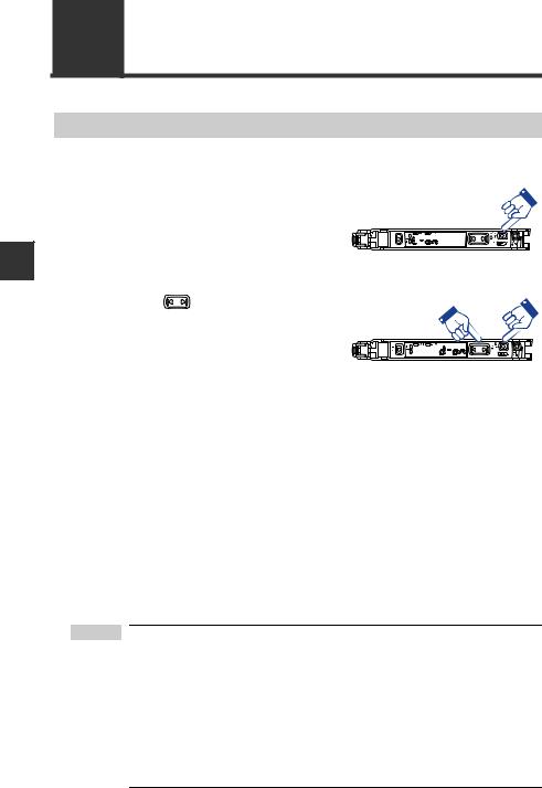
3-2 Switching Output
Output Switch (L-on/D-on)
This function configures when the output turns ON.
1 |
When the current received light inten- |
|
sity is displayed, press the [MODE] but- |
||
|
ton. |
|
|
The current output condition (L-on or D- |
|
|
on) is displayed.*1 |
|
2 |
Press the |
button to switch the out- |
put condition, and then press the |
||
[MODE] button.
Select "D-on" if you want to output the ON signal when the beam is blocked (a work-
piece is present.) for a thrubeam or retro-reflective model.
Select "L-on" if you want to output the ON signal when the beam is received (a workpiece is present.) for the reflective model.
The output condition is switched, and the current received light intensity is displayed.*2
*1 If you do nothing for 3 seconds or more or press the [MODE] button, the received light intensity display is automatically restored.
*2 When using the sub-display, the screen will switch between the current received light intensity J L-on/D-on screen J sub-display J current received light intensity and so forth each time the [MODE] button is pressed.
 "Sub Display" (page 4-22)
 Point • When in area detection mode, rising edge detection mode, falling edge detection mode, counter output mode, or when the LV-S31 is connected, this function works as a normally-open/normally- closed switch.
"Area detection mode" (page 4-14) "Rising edge detection mode" (page 4-16) "Falling edge detection mode" (page 4-16) "Counter output mode" (page 4-35)
•With the 2-output type, channels 1 and 2 can be configured separately.
3-4 |
- Digital Laser Sensor LV-N10 Series User's Manual - |
|

3-3 Adjusting the Sensitivity
In this manual, the value at which the sensor amplifier's ON/OFF output switches is expressed as the "setting value". The process of adjusting the setting value is expressed as "adjusting the sensitivity". This section explains the method of adjusting the sensitivity.
List of Sensitivity Adjustment Methods
The methods of adjusting the LV-N10 series sensitivity is largely classified into 2 types.
(1) Preset
At the same time as adjusting the sensitivity, the received light intensity can be calibrated to "100.0" or ".0" using simple operations.
This method can decrease the variation of the received light intensity depending on the contents of the detection and the workpiece, and is useful for predictive maintenance.
However, this is not suitable for when difference in received light intensity varies little with or without a workpiece, such as when detecting a transparent workpiece.
(2) Calibration
The sensitivity can be adjusted with simple operations. The received light intensity is not compensated.
This method is used to adjust without calibrating the received light intensity, or when highly accurate detection is required.
Calibration can be performed in the preset state.
Basic method of selecting sensitivity adjustment method
Sensitivity |
|
Usage |
Function |
Details |
Reference |
adjustment |
|
||||
method |
|
|
|
|
|
|
|
Using a thrubeam/retro-reflec- |
Preset |
The sensitivity is adjusted just by |
|
|
|
pressing the [PRESET] button when |
3-6 |
||
|
|
tive model |
|||
|
|
|
a workpiece is absent. |
|
|
|
Basic |
|
|
|
|
|
|
|
|
|
|
|
|
Maximum sensi- |
The sensitivity is adjusted just by |
|
|
|
|
|
|
||
|
|
Using a reflective model |
pressing and holding the [PRESET] |
3-8 |
|
|
|
tivity preset |
|||
|
|
|
button when a workpiece is absent. |
|
|
Preset |
|
|
|
|
|
|
|
|
|
|
|
|
"100.0" and ".0" cannot be set |
|
The states at which to display |
|
|
|
|
|
|
||
|
|
regardless of whether a work- |
Work-preset |
"100.0" and ".0" can be set ran- |
3-7 |
|
At times |
piece is present or absent. |
|
domly. |
|
|
like this |
The moving workpiece moves |
|
The sensitivity can be calibrated |
|
|
|
Full auto preset |
using a workpiece which moves at |
3-9 |
|
|
|
quickly |
|||
|
|
|
high speed. |
|
|
|
|
|
|
|
|
|
|
|
|
|
|
|
|
|
Two-point |
The setting can be established just |
|
|
Basic |
Using a thrubeam/retro-reflec- |
by pressing the [SET] button once |
3-12 |
|
|
tive / reflective model |
calibration |
when a workpiece is present and |
||
|
|
|
|||
|
|
|
|
absent. |
|
|
|
|
|
|
|
|
|
The moving workpiece moves |
Full auto |
The sensitivity can be calibrated |
|
|
|
using a workpiece which moves at |
3-9 |
||
|
|
quickly |
calibration |
||
|
|
high speed. |
|
||
Calibration |
|
|
|
|
|
|
|
|
|
|
|
|
Using in an easily contami- |
Maximum sensi- |
This setting prevents malfunctions |
|
|
|
|
|
|||
|
At times |
even when using in an easily con- |
3-8 |
||
|
nated environment |
tivity calibration |
|||
|
like this |
taminated environment. |
|
||
|
|
|
|
||
|
|
Using with positioning |
Positioning cali- |
A setting suitable for positioning can |
3-15 |
|
|
bration |
be made. |
||
|
|
|
|
||
|
|
|
|
|
|
|
|
Using with highly accurate |
Percentage cali- |
This is useful for calibrating from an |
3-16 |
|
|
detection |
bration |
external device, such as a PLC. |
|
|
|
|
|||
|
|
|
|
|
|
3
Operation Basic
- Digital Laser Sensor LV-N10 Series User's Manual - |
3-5 |
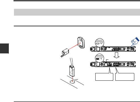
3
Operation Basic
3-3 Adjusting the Sensitivity
Preset Function
Enabling the preset function
When the PST indicator is not lit, press the [PRESET] button
The PST indicator lights in green. The current value is set to "100.0" and the setting value is set to "50.0".
 Green PST lights up
|
Setting value |
Current value is |
Workpiece |
is " . " |
" . " |
Disabling the preset function
When the PST indicator is lit, press and hold the [PRESET] button.
•The PST indicator turns off, indicating that the preset function has been disabled.
•Once the preset function is disabled, the setting value is recalculated while retaining the ratio of the setting value and received light intensity.
3-6 |
- Digital Laser Sensor LV-N10 Series User's Manual - |
|
Loading...