


LV-SB
Table of contents
 Loading...
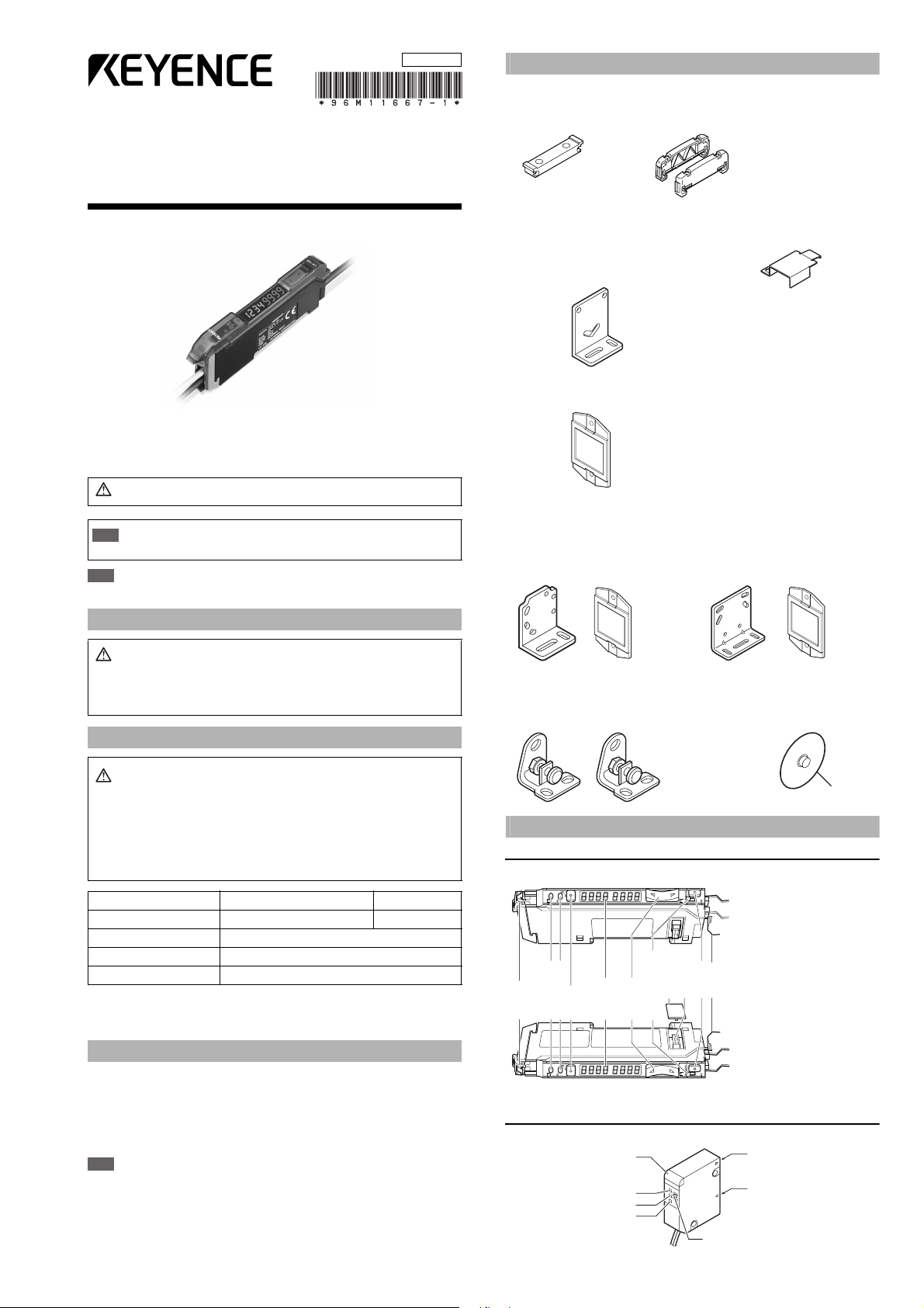
1
E LV-S-IM
Ultra-small Digital Laser Sensor
LV-S Series (Type B)
Instruction Manual
■ Symbols
The following warning symbols are used to alert you to safety precautions and
to prevent human injury and/or damage to property when using this product.
Note
Provides additional information on proper operations that can be easily mistaken.
Safety Information for LV-S series
Safety precautions on laser products
* The classification is implemented based on IEC60825-1 following the
requirements of Laser Notice No.50 of FDA (CDRH).
Safety Measures for the Laser
■ Laser emission stop input
The laser emission can be stopped by selecting the “Laser emission stop” signal
(20 ms or more) from the input functions and inputting it externally.
The emission stops while the signal is being input. The laser beam is emitted in 20 ms
after the signal input is canceled. The control output functions according to the
received light intensity even while laser emission stop is input.
Note
When the power is turned on, even when the laser emission stop signal is
input, the laser is emitted for about 60 ms for self-diagnostic purpose.
Accessories
■ Amplifier
Mounting bracket: 1 End unit: 2 Instruction Manual: 1
Supplied with LV-11SB (P) Supplied with LV-12SB (P)
■
LV-S31 dedicated accessories
■
LV-S62 dedicated accessories
Reflector (R-6L): 1
■
LV-S61 dedicated accessories
Mounting bracket: 1
Plate nut: 1
M2 x 12 screw: 2
Reflector (R-6): 1
■ LV-S71/S72 dedicated accessories
Mounting bracket: 2 Nut: 4
Beam axis adjustment cap: 1
Facing ring: 2
Washer: 2
Identifying Part Names
Amplifier
■ LV-12SB (P) (Expansion unit)
■ LV-11SB (P) (Main unit)
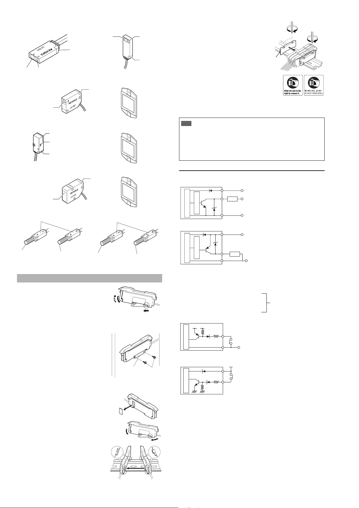
Sensor head
■ LV- S3 1
Warning
Failure to follow instructions may lead to injury.
Important
Indicates warnings and restrictions that must be followed during
operations.
Warning
•
This product is just intended to detect the object(s). Do not use this
product for the purpose to protect a human body or a part of human
body.
•
This product is not intended for use as explosion-proof product. Do not
use this product in hazardous location and/or potentially explosive
atmosphere.
Warning
• U se of controls or adjustments or performance of procedures
other than those specified herein may result in hazardous radia-
tion exposure.
• This product employs a semiconductor laser for its light source.
• Follow the instructions mentioned in this manual. Otherwise, injury
to the human body (eyes and skin) may result.
Precautions on class 1 laser products
•
Do not disassemble this product. Laser emission from this product
is not automatically stopped when it is disassembled.
•
Do not stare into the beam.
Sensor head LV-S31/S41/S41L/S61/S71/S72 LV-S62/S63
Wavelength 655 nm 660 nm
Output 290 μW
FDA(CDRH) Part 1040.10* Class 1 Laser Product
IEC 60825-1 Class 1 Laser Product
■
LV-S41/S41L dedicated accessories
Mounting bracket: 1
Mounting bracket: 1
Plate nut: 1
M3 x 15 screw: 2
Adjustment screwdriver: 1
■
LV-S63 dedicated accessories
L-shaped mounting bracket: 1
M4 nut: 3
M4 x 30 screw: 3
Reflector (R-9): 1
ø30
Output indicator lamp
(for control output 2)
SET button
Digital monitor
Manual button
Channel selection switch
(display settings)
Connector protection
cover
Extension connector
MODE button
Dust cover
Output indicator lamp
(for control output 1)
Hold lock bar
Receiving section
Transmitting section
Operation indicator (red)
FAR indicator (red)
J
U
S
T
i
n
d
i
c
a
t
o
r
(
g
r
e
e
n
)
NEAR indicator (red)
F
F
N
J
N
Adjustment trimmer
96M11667
2
E LV-S-IM
■ LV- S 41
■ LV- S 61
■ LV- S 62
■ LV- S 63
■ LV-S71
The operation indicator works in conjunction with the Output selected at the
channel selection switch. (It does with Output 1 in area detection mode.)
Mounting the Amplifier Unit
■ Mounting on a DIN rail
1)
Align the claw at the bottom of the main body with the
DIN rail. While pushing the main body in the direction
of the arrow 1, slant it in the direction of the arrow 2
.
2)
To dismount the sensor, raise the main body
in the direction of the arrow 3 while pushing
the main body in the direction of the arrow 1.
■
Installation using the mounting bracket (accessory) (LV-11SB/11SBP only)
Mount the amplifier unit using the supplied
mounting bracket as shown in the figure.
■ Connecting several amplifier units
Up to 16 expansion units LV-12SB can be installed to the main unit LV-11SB.
1 Remove the protection cover on the side of the
main unit.
2 Install the amplifier one by one on the DIN rail.
3 Engage the two claws of the expansion
unit with the recesses on the main unit
side until you hear a click sound.
4 Install the end units on both ends of
the amplifier unit.
Fasten the screws on the top of the
end units (at two positions on both
end units) with the Philips screw-
driver.
* The stickers on the right are provided. Attach
the sticker on the place near the amplifier unit.
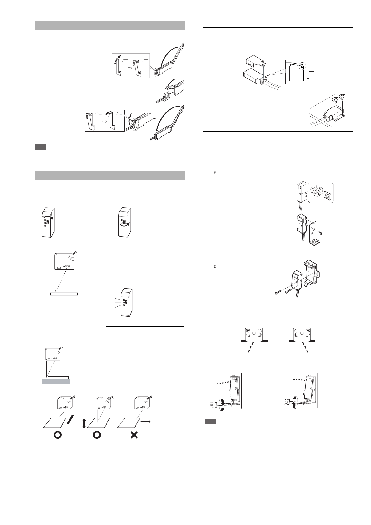
■ Removing the amplifier unit
1 Remove the end units.
2 Slide the expansion unit and remove it one by one.
Input/Output Circuit Schematic
■ Output circuit
LV-11SB/12SB (NPN output type)
LV-11SBP/12SBP (PNP output type)
The power of the expansion unit LV-12SB (P) is supplied by the Extension connec-
tor on the side of the main unit LV-11SB (P). The power wires (brown and blue) of
the main unit and those of the expansion unit are unified inside by the connector.
■ Input circuit
LV-11SB/12SB (NPN output type)
LV-11SBP/12SBP (PNP output type)
Receiving
section
Transmitting section
Operation
indicator
(red)
■ LV- S4 1 L
Transmitting
section
Receiving
section
Operation
indicator
(red)
Transmitting section,
Receiving section
Operation
indicator (red)
Reflector (accessory)
Reflector (accessory)
Transmitting section,
Receiving section
Spot selection switch
Operation indicator
(red)
Transmitting section,
Receiving section
Operation
indicator (red)
Reflector (accessory)
Operation indicator (red)
Transmitting section
Receiving section
Tra ns mi t te r
Receiver
■ LV- S7 2
Operation indicator (red)
Transmitting section
Receiving section
Tra ns m it te r
Receive
r
(1)
(2)
(3)
M3 screw
Mounting bracket
(OP-25431)
(1)
(2)
Important
•
When installing additional expansion unit, be sure to use the DIN rail and the end units.
• Turn off the power when installing or removing the unit.
• Do not remove the protective cover of the extension connector on the
amplifier expansion unit that is added at the end.
•
Do not remove the amplifier unit with all added units attached, from the DIN rail.
•
Verify the operation ambient temperature after addi tional installati on. (“Specifications” page 11)
•
Do not use full calibration functions or stability output when the expansion unit of
the LV-S Series is connected to a device with full calibration functions (such as
FST or PS-T) via external input. Doing so may lead to product malfunctions.
Two end units are
supplied with an
expansion unit.
OP-26751
DC5-40V
DC12-24V
Load
Black/white (control output 1/2)
Brown *
Blue *
Sensor main circuit
Overcurrent protection circuit
0V
* LV-11SB only
DC12-24V
Load
Black/white (control output 1/2)
Brown *
Blue *
Sensor main circuit
Overcurrent protection circuit
0V
* LV-11SBP only
• Not to be used
• Light emission stop input
• External calibration input
• Setting value bank selection input
• Received light intensity shift input
Select either one.
(switched by the amplifier
function selection)
(Short-circuit current 1 mA max.)
PLC etc.
Pink (input)
Sensor main circuit
Blue *
DC3.3V
0V
* LV-11SB only
PLC etc.
Pink (input)
Sensor main circuit
Brown *
DC12-24V
* LV-11SBP only
(Short-circuit
current 2 mA max.)
3
E LV-S-IM
Connecting the Sensor Head and the Amplifier Unit
■ How to connect the amplifier unit and the connector
1 Open the dust cover, and tilt the
hold-lock lever.
2 Raise the hook, and insert the
connector to the very end.
3
Lower the hook and
hook the part shown
in the figure, and
then raise the hold-
lock lever.
Note
When shortening the sensor head cable, follow the instructions given in the
“Sensor Head Connector Assembly Procedures” included with the sensor
head.
Mounting and Adjusting the Sensor Head
LV- S3 1
■ Adjusting the trimmer (detection position)
The detection range can be selected as desired by adjusting the trimmer.
■ Adjusting the center of detection
1
Place the workpiece at the position you
want to set as the center of detection.
2 Turn the trimmer until JUST
indicator (2) illuminates in green.
Finer adjustment is possible by looking at the display on the amplifier (page 9).
■ Detecting a height difference
A stable detection is made possible by
adjusting the trimmer so that the middle
point of the height comes to the center of
detection.
■ Movement directions of the workpiece
LV-S41/S41L
Be sure to use the supplied mounting bracket.
1 Press the mounting bracket on the sensor head.
Be sure to hook the A portion of the mounting bracket on the B portion of
the sensor head.
2 Install the sensor head on the flat surface with the
M3 screws as shown in the following figure.
(The M3 screw is not an accessory.)
LV-S62
Mount the sensor head using either L-shaped mounting bracket (OP-84350),
rear mounting bracket (OP-84349), side mounting bracket (OP-84351) sold
separately.
■ L-shaped mounting bracket (sold separately: OP-84350)
Mounting bracket 1
Plate nut 1
M3 x 7.3 screw 1
1 Insert the plate nut to the head.
2 Insert the protrusion on the amplifier for
securing the bracket into the hole at the
upper part of the bracket.
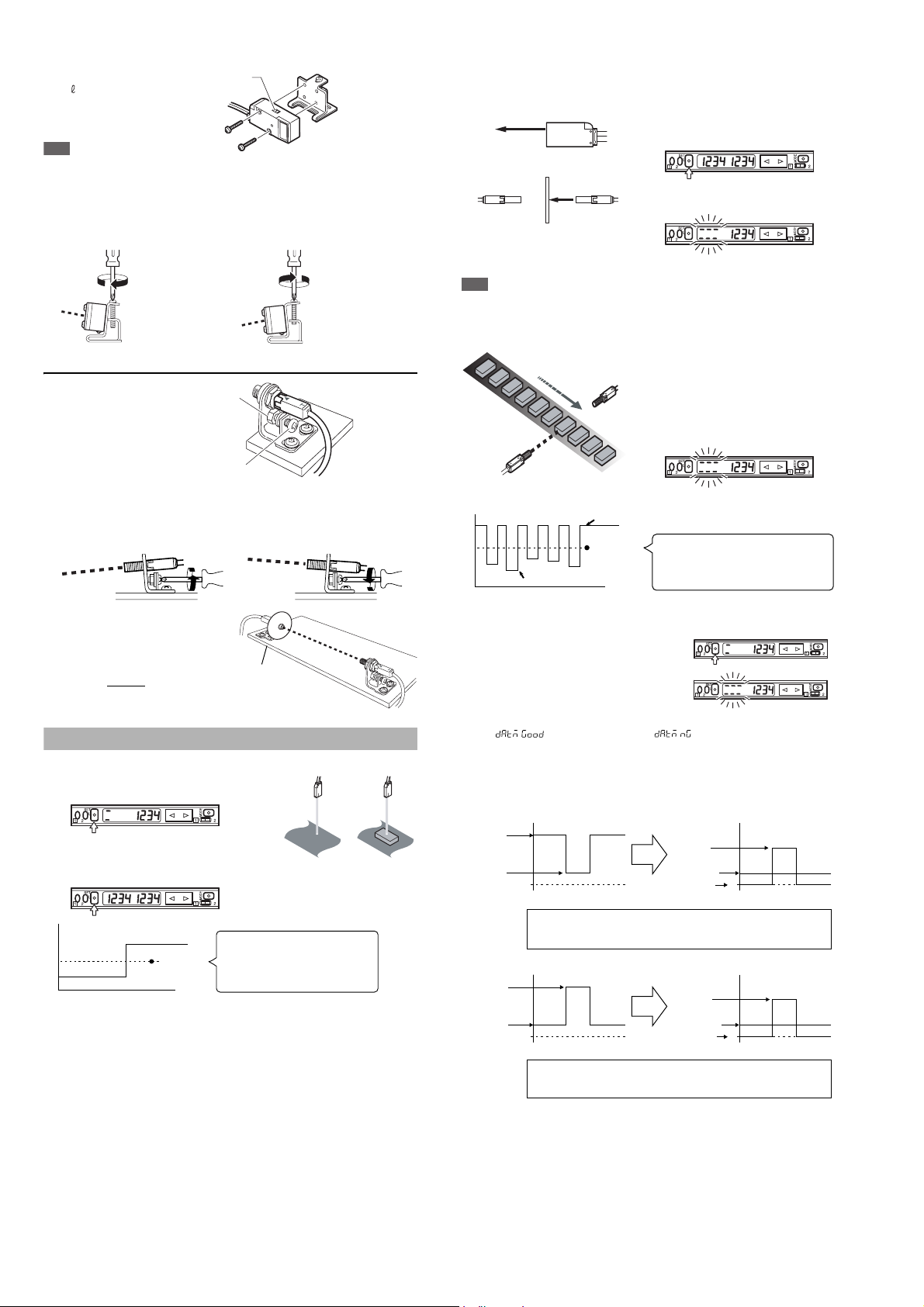
■ Rear mounting bracket (sold separately: OP-84349)
Mounting bracket 1
M3 x 18 screw 2
• Adjusting the beam axis
(1) The beam axis angle can be adjusted horizontally by swinging the
bracket to the left and right with screws (a), (b) and (c) loosened. In order
to tighten the screws, be sure to tighten screw (b) first.
(2) The angle of the beam axis can be changed downward if the screw indi-
cated by the arrow is tightened, and upward if loosened.
When detecting the target
from a long distance, turn the
trimmer clockwise to adjust.
When detecting the target
from a short distance, turn the
trimmer counterclockwise to
adjust.
F
J
N
F
N
F
J
N
F
N
When (1) illuminates, turn the
trimmer clockwise until (2)
illuminates.
When (2) illuminates, the
adjustment is complete.
When (3) illuminates, turn the
trimmer counterclockwise
until (2) illuminates.
F
J
N
F
N
(1)
(2)
(3)
Middle point
Movement
direction
Detecting
object
Detecting
object
Detecting
object
Movement
direction
Movement
direction
Important
Be sure to adjust the beam axis in the order of (1) and (2).
If the order is reversed, the screws in (1) may be damaged.
A
B
Limit the tight-
ening torque
up to 0.5Nm
Limit the tightening
torque up to 0.5Nm
(a)
(b)
(c)
(a)
(b)
(c)
When you want to lower the beam axis. When you want to raise the beam axis.
4
E LV-S-IM
■ Side mounting bracket (sold separately: OP-84351)
Mounting bracket 1
M3 x 18 screw 2
Note
When mounting the sensor head in the opposite direction as described previ-
ously, set the spot toggle switch before mounting.
• Adjusting the beam axis
The angle of the beam axis can be changed upward if the screw indicated by
the arrow is tightened, and downward if loosened.
LV-S71/S72
Mount the sensor head such
that the letter “T” (on the
transmitter) or “R” (on the
receiver) faces upward. The
side where the operation indi-
cator illuminates should face
upward.
• Adjusting the beam axis
The angle of the beam axis can be changed downward if the screw indicated
by the arrow is tightened, and upward if loosened.
Adjust the spot to be emitted at the
center on the receiver.
The adjustment is facilitated by
attaching the beam-axis adjustment
cap supplied with the sensor head to
the tip of the receiver
. Once the
adjustment is complete, remove the
beam-axis adjustment cap.
Setting Sensitivity
■ 2-point calibration
1 Press the SET button once without a
workpiece being placed.
2 Place a workpiece at the designated
position, and quickly press the SET
button once again.
*
If the sensitivity difference does not have enough room, “
++++
” flashes after
the calibration is complete. The setting value is changed at this time, too.
■ Maximum sensitivity setting
Set the sensitivity without a workpiece in the case of the reflective type, and with
a workpiece in the case of the transmission type.
1 Press the SET button for three
seconds in the state as shown in
the figure on the left.
The indication flashes when the setting
is complete.
2 Release the SET button.
Note
In the transmission type, if the value for the maximum sensitivity setting is the same as
DSC, the device will not operate correctly, so do not use the same value.
■ Full-auto calibration (not available for the LV-S31)
1
Let the workpiece pass while the SET
button is being pressed for three
seconds. (The sensitivity is set
according to the received light intensity
while the SET button is pressed.)
2
The indication flashes when the
setting is complete.
3 Release the SET button.
Perform 2-point calibration if the setting cannot be configured as desired.
■ Zero datum calibration (not available for the LV-S31)
1 Press the SET button quickly without a
workpiece being placed.
2 Press the SET button for at least three
seconds. When the indication flashes,
release the button.
3 The calibration is complete when
" " is displayed. When " " is displayed, switch the
channel toggle switch to "2" and check the contents of the alarm.
*The alarm contents are only displayed when "Auto" is selected for "ALrt",
the operation of control output 2 in "4. Detection mode selection". (For
information about the display, see "Toggling the display" on page 9.)
Transmission/retro-reflective types
Reflective type
Spot toggle
switch
Limit the tightening
torque up to 0.5Nm
When you want to raise the beam axis. When you want to lower the beam axis.
Fixing nut
Beam axis
adjusting screw
Limit the tightening
torque up to 1.2 Nm.
When you want to lower the beam axis When you want to raise the beam axis
Beam axis
adjustment cap
12
Received light intensity
Setting value
Time
The value set at the intermediate point
between the received light intensity
measured when the SET button is pressed
for the first time and that measured when it
is pressed for the second time.
1
2
Reflective type
Transmission type
With no workpiece
With workpiece
Received light intensity
Setting value
Time
MAX
MIN
The value is set at the intermediate point
between the MAX value and the MIN value
of the received light intensity measured
while the SET button is pressed.
Received light
intensity without
workpiece
0 0
Received light
intensity with
workpiece
(Blocked light)
Received light
intensity without
workpiece
Blocked light
Setting value
In the transmission or retro-reflective type, when zero datum calibration is performed
without a workpiece, the received light intensity without a workpiece is used as zero and
the value indicates the amount of blocked light. The setting value is set automatically.
0 0
Received light
intensity without
workpiece
Received light
intensity with
workpiece
(Entered light)
Received light
intensity without
workpiece
Entered light
Setting value
In the reflective type, when zero datum calibration is performed without a
workpiece, the received light intensity without a workpiece is used as zero and the
value indicates the amount of entered light. The setting value is set automatically.
Loading...