


96M0747???
DUAL DIGITAL FIBER
SENSOR
FS-V22/22G/22R(P)/22X
Instruction Manual
3. Amplifier Expansion
Up to 16 sub units can be connected to each main unit.
1) Remove the expansion protective cover from the main unit.
2) Mount each amplifier to the DIN rail.
3) Press the two claws of each sub unit to the grooves on the main unit until
the claws snap. 


 4) Mount the end units to the leftand


 right-hand sides of the whole amplifi-

ers in the method shown in the figure at step 2.
5) Check that the amplifiers are securely sandwiched by the end units. Use a Phillips screwdriver and securely tighten the screws on the
end units (i.e., two screws on each end unit).
1.Safety Precautions

 WARNING
•This product is used to detect targets. Do not apply the product to safety circuits for human protection.
•This product is not of explosion-proof construction. Do not use the products in places with flammable gas, liquid, or dust.
•This product is a sensor of DC power supply type. Do not apply AC power. The product may explode or burn if 100 VAC or a higher voltage is applied.
Check that all the accessories are ready before use.
• Accessories |
|
|
Instruction |
End units (x2) |
Expansion Sticker (x1) |
manual (x1) |
|
|
|
|
Slide the unit to the |
|
|
right to remove it. |
4. Connecting Fiber Unit
1) |
Open the dust cover in the direction |
|
shown by arrow . |
2) |
Move down the fiber lock lever in the |
|
direction shown by arrow . |
3) |
Insert a fiber unit into the fiber inser- |
|
tion holes to a length of the fiber in- |
|
sertion sign (i.e., approximately 14 |
|
mm). |
Fiber insertion sign 4) |
Move up and return the fiber lock lever |
|
in the direction shown by arrow . |
Note:If a thin fiber unit is used, an adapter provided with the thin fiber unit will be required.
Unless the right adapter is connected, the thin fiber unit will not detect targets correctly.
Cable outer dia. |
Adapter |
Appearance |
ø1.3 |
Adapter A |
|
ø1.0 |
Adapter B |
|
•To connect the coaxial reflective type fiber unit to the amplifier, connect the single-core fiber to the transmitter side, and connect the multiplecore fiber to the receiver side.
2. Part Names
Fiber lock lever
Transmitter
Single-core fiber
Multi-core fiber
Receiver
Operation indicator*
Set button
Digital |
Preset value (PV) |
|
|
|
|||
green indicator |
|||
monitor |
|
|
|
Manual |
Current value |
|
|
|
|
||
button |
(CV) red indicator |
||
Expansion protective cover
Expansion connector  Mode button
Output selector
Cable
Dust cover
•To remove the amplifiers added, take the steps opposite to the mounting procedure.
•Put the provided sticker close to the sensor.
Note • The FS-V22/22G/22R(P)/22X incorporates a mutual interference prevention function, thus allowing the close mounting of a number of fiber units in the following modes.
|
Power mode |
FINE |
TURBO |
SUPER |
ULTRA |
|
TURBO |
TURBO |
|||
|
|
|
|
||
|
Number of |
4 |
8 |
8 |
8 |
|
units connected |
||||
|
|
|
|
|
|
|
|
|
|
|
|
5. I/O Cricuit
Refer to the following I/O circuit diagram when connecting the unit to pe-
ripheral devices. |
|
FS-V22/22G/22R/22X |
FS-V22RP |
* The operation indicator of the FS-V22X (infrared model) will not be lit.
|
|
|
|
|
DC 12 to 24V |
|
|
Photoelectric mainsensorcircuit |
Overcurrent circuitprotection |
Max. 100mA |
|
Photoelectric mainsensorcircuit |
Overcurrent circuitprotection |
(Control output) |
|
Load |
DC 5 to 40V |
|
|||||
|
Black |
(Control output) |
|
|
Black |
Max. 100mA |
|
|
|
|
|
|
|
Load |
DC 5 to 40V |
|
0 V |
|
|
|
|
|
|
1
6.Making Sensitivity Settings
●Full Auto Calibration
In this mode, the PV will be set to the mean value of the maximum and minimum incident values obtained within a certain period.
Use this mode to detect moving workpieces.
1)Press the set button for a minimum of three seconds while the target workpiece is passing the sensing area of the fiber unit.
•While the set button is pressed, the sensitivity of the sensor will be set according to the incident values.
Workpiece
 The display will 3 s min. flash when the
settings are completed.
•When the setting is finished, the digital monitor will display the PV in green.
PV (green) |
CV (red) |
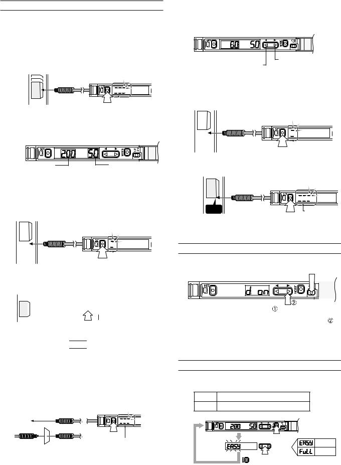
●Two-point Calibration
In this mode, the PV used will be the mean value of two sensing values obtained with and without a workpiece.
1)Press the set button for a moment without the workpiece in the sensing area (i.e., in front of the fiber unit).
Workpiece
 The display will be lit when the workpiece is detected.
2)Locate the workpiece in the sensing area (i.e., in front of the fiber unit). Then press the set button for a moment.
Workpiece 


 The PV will appear when
the settings are completed.
* If there is extremely little difference in sensitivity between the sensing values, the display 


 will flash on completion of tuning.
●Maximum Sensitivity Setting
If the sensing performance of the sensor drops due to dust or dirt, set the sensitivity of the sensor to maximum.
1)Press the set button without a workpiece if the fiber unit is a reflective model. Press the set button with a workpiece if the fiber unit is a through-beam model. In both cases, press the set button for a minimum of three seconds.
“Reflective model”
“Through-beam model”
3 s min.
The display will flash for a moment when the setting is finished. Then the PV will be displayed.
* If the sensing distance is insufficient, make sensitivity settings in the sensor in two-point tuning mode.
●Manua| Calibration
In this mode, make manual PV settings.
PV 
The PV value decreases by pressing this side of the manual button.
● Positioning Calibration
The PV value increases by pressing this side of the manual button.
In this mode, a workpiece will be detected when the front edge of the workpiece has reached a preset position.
1)Press the set button for a moment without the workpiece in the sensing area (i.e., in front of the fiber unit).
Workpiece
 The display will be lit when the workpiece is detected.
2) Locate the front edge of the workpiece in the sensing area. Then press the set button for a minimum of three seconds.
Workpiece |
|
Front edge |
The display will flash |
|
|
|
3 s min. for a moment when |
|
the setting is |
|
finished. Then the |
|
PV will be displayed. |
7. Selecting Output
Either light-ON mode or dark-ON mode is selectable.
Press the mode button. 
|
|
|
|
|
|
|
|
|
|
|
|
|
|
|
|
|
|
|
|
|
|
|
|
|
Press the manual button |
||||
The display indicates that |
|||||||||
the sensor is in dark-ON |
within five seconds after |
||||||||
mode. The CV will be |
pressing the mode button . |
||||||||
displayed if no buttons are |
|
|
|
|
|
||||
operated for approximately |
|
|
|
|
|
||||
five seconds. |
|
|
|
|
|
||||
•Take the same steps to set the sensor to light-ON mode again.
8.User-friendly Functions
●Access Mode Selection
Two modes are available to the display of values and menu items.
EASY |
Only basic functions are displayed. |
|
||
FULL |
All available functions are displayed. |
|
||
|
|
Press 3 s min. |
|
|
|
|
Select |
EASY |
|
Completion |
FULL |
|||
|
||||
of selection |
Press 3 s min. |
|
||
|
|
|
||
• The mode is set to EASY before shipping.
2
 Loading...