


 Loading...
96M0744 |
|
SAFETY PRECAUTIONS |
|
RGBDigitalFiberopticSensors
CZ Series
Instruction Manual
This manual describes the instructions, operating procedures and precautions for using the CZ Series.
Before beginning operation, please read this manual carefully to get the most from your CZ Series.
Keep this manual handy for future reference.

 WARNING
•The CZ Series is intended for the detection of target objects. Do not use the CZ Series in a safety circuit to protect the human body.
•The CZ Series does not have an explosion-proof structure. Do not use it in a location where any flammable gases, liquid or powder exist.
ACCESSORIES
Instruction manual (This manual): 1
Mounting bracket: 1 |
Plastic screw driver: 1 |
SPECIFICATIONS
Amplifier
Model |
CZ-V1 |
|
Light source |
Red LED, Green LED, Blue LED |
|
Response time |
300 s/1 ms (switch selectable) |
|
|
Output: Red LED, Calibration: Orange LED, |
|
Indicators |
External synchronization input: Green LED, |
|
|
Matching rate/received light intensity: LCD (Red/Green) |
|
Error indication |
Excess light intensity, insufficient light intensity, |
|
insufficient color difference |
||
|
||
Calibration method |
1-point/2-point calibration (switch selectable) |
|
Tolerance value |
Numerical value setting on digital display |
|
adjustment |
||
|
||
Differentiation mode |
C mode/C + I mode/I mode (switch selectable) |
|
Timer function |
Timer OFF/OFF-delay timer (40 ms) (switch selectable) |
|
|
Match output: Turns on when target color |
|
Output mode |
matches registered color. |
|
selection |
Mismatch output: Turns on when target color is different |
|
|
from registered color. (switch selectable) |
|
External synchro- |
Response speed: 500 s max. |
|
nization input |
||
|
||
External calibration |
Input response time: 20 ms min. |
|
input |
||
|
||
Registered color |
8-bank selection (By external input or key operation), |
|
selection |
Input response time: 20 ms min. |
|
Control output |
NPN open-collector: 40 VDC max. (100 mA max.), |
|
Residual voltage: 1.0 V max. |
||
|
||
Protection circuit |
Reverse-polarity protection (power supply), |
|
overcurrent protection (output), surge protection (output) |
||
|
||
Power supply |
12 to 24 VDC±10%, Ripple (P-P): 10% max. |
|
Current |
75 mA max. |
|
consumption |
||
|
||
Ambient light |
Incandescent lamp: 5,000 lux max., |
|
Sunlight: 10,000 lux max. |
||
|
||
Ambient |
–10 to +55°C (14 to 131°F), No freezing |
|
temperature 1. |
||
|
||
Relative humidity |
35 to 85%, No condensation |
|
Vibration |
10 to 55 Hz, 1.5 mm double amplitude in X, Y, and Z |
|
directions, 2 hours respectively |
||
|
||
Shock |
500 m/s2 in X, Y, and Z directions, 3 times respectively |
|
Housing material |
Polycarbonate |
|
Weight (including |
Approx. 115 g |
|
2 m cable) |
||
|
1
Fiber unit
Type |
Reflective |
|
|
|
|
|
Adjustable small beam spot |
Adjustable small beam spot, sideview |
Model |
CZ-10 |
CZ-11 |
Detection range |
10 to 30 mm |
3 to 15 mm |
Smallest spot diameter |
0.9 to 3.5 mm dia. |
0.9 to 1.5 mm dia. |
Minimum bend radius |
R25 mm |
|
|
|
|
Enclosure rating |
IP40 |
|
|
|
|
Ambient temperature |
–40 to +70°C (–40 to 158°F), No freezing |
|
|
|
|
Relative humidity |
35 to 85%, No condensation |
|
|
|
|
Fiber length |
2 m (free-cut) |
1 m (free-cut) |
|
|
|
Housing material |
Lens housing: Aluminum, Fiber case: Stainless steel |
|
|
|
|
Weight |
Approx. 5 g |
Approx. 13 g |
|
|
|
|
|
|
Detection method |
Reflective |
|
|
|
|
Model |
CZ-40 |
CZ-41 |
|
|
|
Type |
Long detecting distance |
Small beam spot |
|
|
|
Detection range |
70±20 mm |
16±4 mm |
|
|
|
Smallest spot diameter |
6 mm dia. |
1 mm dia. |
|
|
|
Minimum bend radius |
R25 mm |
R15 mm |
Enclosure rating |
IP67 |
|
|
|
|
Ambient temperature |
–40 to +70°C (–40 to 158°F), No freezing |
|
|
|
|
Relative humidity |
35 to 85%, No condensation |
|
|
|
|
Fiber length |
2 m (free-cut) |
|
|
|
|
Housing material |
Polyarylate |
|
|
|
|
Weight |
Approx. 27 g |
|
|
|
|
1.When several units are connected, the acceptable ambient temperature varies depending on the conditions given below. To connect several units, be sure to mount them to a DIN rail (metallic plate). Ensure that the output current is 20 mA max.
•When 3 to 10 units are connected: -10 to +50°C (14 to 122°F)
•When 11 to 16 units are connected: -10 to +45°C (14 to 113°F)

CONNECTING FIBER UNIT AND AMPLIFIER
1.Tilt the quick-release lever.
2.Push the single-core fiber to the transmitter side, and the multiplecore fiber to the receiver side as far as they will go (Approx. 14 mm of the fiber will be inserted.).
*Inserting the fiber in the wrong side will decrease the original detection performance. Be sure to check the markings on the amplifier’s lateral side before inserting the fiber.
3. Raise the quick-release lever.
1 |
3 |
|
Quick-release lever |
Transmitter side |
|
2 |
(with markings) |
|
Receiver side |
||
Single-core fiber |
|
|
(with markings) |
|
|
Multiple-core fiber |
Multiple-core |
|
|
Single-core |
|
|
(Transmitter side) |
(Receiver side) |
MOUNTING AMPLIFIER
■Mounting/detaching amplifier to/from DIN rail or mounting bracket
Hook the claw on the rear side of the amplifier onto the DIN rail or the mounting bracket, and then hook the front side claw to the rail or bracket while pressing the amplifier forward. To detach the amplifier, unhook the front claw by lifting the amplifier front side while pressing it
forward. Mounting Detaching
■ Side mounting
Using the side holes of the supplied mounting bracket, secure the amplifier with the screws.
CONNECTING SEVERAL AMPLIFIERS
■ Mounting expansion units
Up to 16 expansion units (FS-T2, FS-M2, FS-V12, PS-T2) can be mounted to the side of the CZ-V1 amplifier.
1. Remove the protective cover on the side of the amplifier.
2. Mount expansion units to the DIN rail |
Remove the |
|
one at a time. |
||
protective cover. |
||
|
3.Slide one expansion unit toward the main unit or another unit. Align the front claws of the units and push them together until you hear a click.
4.Secure the units together by pushing the end units (included in the expansion unit) from both sides.
|
|
Align the claw. |
|
|
End unit (included with |
|
Expansion |
the expansion unit) |
Main unit |
|
|
units |
|
Up to 16 expansion units can be connected.
The sticker on the right is included with the expansion unit. Attach the sticker close to the sensor units.
■ DETACHING EXPANSION UNITS FROM DIN RAIL
1.Detach the end units.
2.Slide the expansion unit that is to be detached. Detach it individually from the DIN rail.
Note 1: When connecting several amplifiers, be sure to use a DIN rail and the end units.
Note 2: Be sure to turn the power off before connecting/disconnecting amplifiers.
Note 3: Do not remove the protective cover on the expansion connector from the outermost unit.
Note 4: Do not detach several units from the DIN rail while they are connected to each other.
Note 5: When several units are connected, confirm that the ambient temperature is appropriate. (See “Specifications” on page 1.)
MOUNTING FIBER UNIT
•Use the supplied special mounting bracket to mount the fiber unit in the desired position according to the location.
•Be sure to limit the tightening torque to 0.3 Nm or less.
Mounting example 1 |
|
|
|
|
|
|
Mounting example 2 |
||
|
|
||||||||
|
|
|
|
|
|
|
|
|
|
|
|
|
|
|
|
|
|
|
|
|
|
|
|
|
|
|
|
|
|
|
|
|
|
|
|
|
|
|
|
|
|
|
|
|
|
|
|
|
|
|
|
|
|
|
|
|
|
|
|
Reference: To cut the fiber to the desired length, use the special cutter included with the fiber unit.
INPUT/OUTPUT CIRCUIT
Connections
Brown |
|
12 to 24 VDC |
|
|
|
||
Black |
100 mA max. |
||
Load |
5 to 40 VDC |
||
|
|||
Pink |
|
External calibration |
|
|
|
||
Purple |
|
External synchronization |
|
|
|
input |
|
Orange/purple |
External bank selection 1 |
|
|
Yellow/purple |
External bank selection 2 |
|
|
Green/purple |
External bank selection 3 |
|
|
Blue |
0 V |
|
Output circuit
Photoelectric sensor |
|
|
Brown |
12 to 24 VDC |
|
|
Black |
||
|
Overcurrent protection |
5 to 40 VDC |
||
|
Load |
|||
main circuit |
100 mA max. |
|
||
Blue |
0 V |
|||
|
||||
|
|
Input circuit
External calibration input
External synchronization input
External bank selection input 1 to 3
+5 V |
+5 V |
Pink |
|
Purple |
|||
Photoelectricsensor maincircuit |
|
||
|
Orange/purple |
||
|
Yellow/purple |
||
|
Blue |
||
|
|
Green/purple |
|
|
|
PLC, etc. |
|
|
|
0 V |
|
Short-circuit current: Approx. 1 mA |
|
||
2
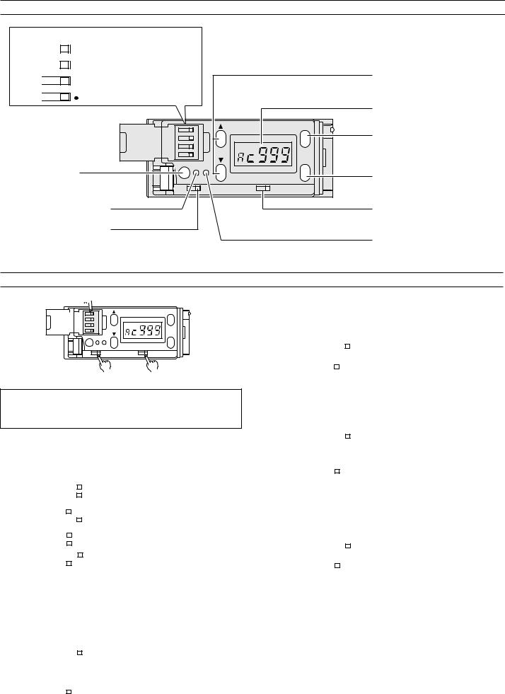
PART NAMES
DIP switches for mode setting
HSPD |
|
FINE High-speed/High-precision |
||
2-P |
|
1-P 2-point/1-point calibration |
||
|
||||
C+I |
|
C |
||
|
||||
|
|
|
|
Differentiation mode |
I |
|
|
selection |
|
|
|
|||
|
|
|
||
|
4 |
|
MODE |
|
3 |
|
|
|
2 |
CH |
|
|
1 |
|
|
|
|
SET |
|
OUT TIM SET |
|
||
|
|
||
Output indicator |
|
|
|
DLY. |
OFF |
N.C |
N.O |
External synchronization input indicator
Timer selection switch
Switches between Timer
OFF and 40 ms OFF-delay.
UP/DOWN key
•Changes sensitivity setting value.
•Changes channels.
LCD display monitor
MODE selection button
•Changes display.
•Shows matching rate.
•Shows setting value.
SET button
Sets sensitivity.
Output selection switch
Switches between N.O. and N.C.
Calibration indicator
SETTING EACH MODE

 DIP switch
|
4 |
|
MODE |
|
|
|
|
|
3 |
|
|
|
2 |
CH |
|
|
1 |
|
|
|
|
SET |
|
OUT TIM SET |
|
||
|
|
||
DLY. |
OFF |
N.C |
N.O |
Timer selection switch Output selection switch
Factory setting
“ ” indicates the factory-set mode. Normally, you should use the CZ-
V1 with the setting indicated by “ ”, and only change the setting if required.
■ Differentiation mode setting (Using DIP switches 1 and 2)
Change the setting according to the detection conditions such as the target color or received light intensity.
|
Mode |
|
Switch |
Description |
||
|
|
|
|
|
|
|
|
C (Color) |
|
|
2 |
Detects color using color components |
|
|
|
1 |
(R, G, and B). |
|||
|
|
|
|
|||
|
|
|
|
|
|
|
|
C + I |
|
|
2 |
Detects color using color components |
|
|
(Color and |
|
|
(R, G, and B) and received light |
||
|
|
|
1 |
|||
|
intensity) |
|
|
intensity (received light quantity). |
||
|
|
|
|
|
||
|
|
|
|
|
|
|
|
|
|
|
|
2 |
|
|
|
|
|
|
|
|
|
I |
or |
|
1 |
Detects color using received light |
|
|
|
|||||
|
(Intensity) |
|
|
intensity (received light quantity). |
||
|
|
|
2 |
|||
|
|
|
1 |
|
||
|
|
|
|
|
||
|
|
|
|
|
|
|
Sensitivity setting in C or C + I mode Go to page 4.
Sensitivity setting in I mode Go to page 5.
■ 1-point/2-point calibration selection1. (Using DIP switch 3)
Change the calibration method.
|
Mode |
|
Switch |
Description |
|
|
|
|
|
|
|
|
1-P |
|
|
|
Detects one specified color. (The |
|
|
|
|
sensitivity is automatically set to detect |
|
|
(1-point |
|
|
3 |
only the one color selected during |
|
calibration) |
|
|
|
|
|
|
|
|
calibration.) |
|
|
|
|
|
|
|
|
2-P |
|
|
|
Differentiates two specified colors. |
|
|
|
|
(The sensitivity is automatically set to |
|
|
(2-point |
|
|
3 |
|
|
|
|
the optimal value to differentiate the |
||
|
calibration) |
|
|
|
|
|
|
|
|
two colors selected during calibration.) |
|
|
|
|
|
|
|
|
|
|
|
|
|
■ FINE/HSPD selection (Using DIP switch 4)
Use HSPD when the detection requires a response speed less than 1 ms.
|
Mode |
Switch |
Description |
||
|
|
|
|
|
|
|
FINE |
|
|
4 |
Differentiates colors with high |
(Fain) |
|
|
precision. |
||
|
|
|
|
||
|
HSPD |
|
|
4 |
Differentiates colors with a high-speed |
|
(High-speed) |
|
|
response of 300 s. |
|
|
|
|
|
||
|
|
|
|
|
|
■ N.O./N.C. selection
Change the setting to invert the output mode.
|
Mode |
Switch |
Description |
||
|
|
|
|
|
|
|
N.O. |
|
|
|
Output is turned on when the target |
|
(Color match |
N.C. |
|
N.O. |
|
|
output) |
|
|
|
color matches the registered color. |
|
|
|
|
|
|
|
N.C. |
|
|
|
Output is turned on when the target |
|
(Color |
|
|
|
|
|
N.C. |
|
N.O. |
color does not match the registered |
|
|
mismatch |
|
|||
|
|
|
|
color. |
|
|
output) |
|
|
|
|
|
|
|
|
|
|
|
|
|
|
|
|
■ Timer OFF/40 ms OFF-delay selection
Change the setting to delay the output timing.
|
Mode |
Switch |
Description |
|||
|
|
|
|
|
|
|
|
Timer OFF |
DLY. |
|
|
OFF |
Output is turned on without any delay. |
|
|
|||||
|
|
|
|
|
|
|
|
40 ms |
DLY. |
|
OFF |
Output is delayed for 40 ms. |
|
|
OFF-delay |
|
||||
|
|
|
|
|
|
|
|
|
|
|
|
|
|
1.The setting of DIP switch 3 is effective only in the C and C + I modes. The setting is unnecessary in I mode.
3
Loading...