


 Loading...
96083E
CCD Thrubeam Type Laser Sensor
IG Series
User’s Manual
Read this manual before using in order to achieve
maximum performance.
After reading, keep this manual in a safe place so that
you can refer to it at any time.
Introduction
This manual describes the basic operations and information of the IG Series.
Read this manual carefully to ensure performance and function of the IG Series for safe use. Keep this manual in a safe place for future reference.
Make sure this manual is kept by an end user finally.
Symbols
The following symbols alert you to matters concerning the prevention of human injury and product damage.
|
DANGER |
Failure to follow instructions and mishandling the product may |
||
|
lead to death or serious injury. |
|||
|
|
|
|
|
|
WARNING |
Failure to follow the instructions may lead to injury. |
||
|
|
|
|
|
|
|
|
|
Failure to follow the instructions may lead to product damage |
|
CAUTION |
|
||
|
|
or failure of the product. |
||
|
|
|
|
|
|
|
|
|
|
Note Provides additional information on proper operations.
 Reference
  Provides advanced and useful information for operation.
Provides reference pages.
Safety Information for IG series
General Precautions
•At startup and during operation, be sure to monitor the functions and performance of this product and confirm normal operation.
•We recommend that you take substantial safety measures to avoid any damage in the event that a problem occurs.
•If the product is modified or used in any way other than those described in the specifications, its functions and performance cannot be guaranteed.
•When this product is used in combination with other devices, the functions and performance may be weaken, depending on the operating conditions, surrounding environment, etc.
•Do not use this product for the purpose of protecting the human body.
•Do not subject each device including peripheral devices to rapid temperature change. Product failure may occur due to condensation.
Safety Precautions on Laser Product
•This product employs a semiconductor laser for its light source.
•Use of controls or adjustments or performance of procedures other than those specified herein may result in hazardous radiation exposure.
•Follow the instructions mentioned in this manual. Other-
WARNING |
wise, injury to the human body (eyes and skin) may |
|
result. |
|
Precautions on class 1 laser products |
•Do not disassemble this product. Laser emission from this product is not automatically stopped when it is disassembled.
•Do not stare into the beam.
Sensor Head |
IG-010/IG-028 |
Wavelength |
660 nm |
Output |
62 ΠW |
|
|
Pluse width |
48 Πs |
|
|
FDA(CDRH)Part1040.10 * |
Class 1 Laser Product |
IEC60825-1 |
Class 1 Laser Product |
|
|
*The classification is based on IEC60825-1 standard following the Laser Notice No.50 from FDA (CDRH).
Laser emission stop input
When the laser emission stop input is set for the external input, the laser emission stops by setting the external input to ON (for 2 ms or more). The laser emission continues to stop while the external input is ON. When the external input is set to OFF, the laser is emitted within 2 ms.
IG-E |
96083E |
1 |
Abnormal Conditions
|
If the following conditions occur, turn OFF the power |
|
|
immediately. Continuing to use this product under abnormal |
|
WARNING |
conditions may cause product failure. |
|
• When water or foreign matter enters the IG Series |
||
|
||
|
• When the IG Series is dropped or the case is damaged |
|
|
• If smoke or unpleasant odor is present. |
|
|
|
Precautions on Use
|
• Use with the correct power source and voltage. Otherwise, |
|
WARNING |
fire, electric shock or product failure may result. |
|
• Do not attempt to open or modify the IG Series. Doing so |
||
|
||
|
may cause fire or electric shock. |
|
|
|
•Before disconnecting the cables, make sure to turn off the main unit and devices connected to the main unit.
CAUTION |
Otherwise, the unit may be damaged. |
•Do not turn off the power while setting items. Some or all of the set data may be lost.
Installation environment
To use this product normally and safely, do not install this product in the following locations. Product failure may occur.
•High-humidity, dusty and poorly-ventilated locations
•High-temperature locations where the unit is exposed to direct sunlight
•Locations where there is corrosive or combustible gas
•Locations where the unit may be directly subjected to vibration or impact
•Locations where water, oil or chemicals may splash onto the unit
•Locations where static electricity tends to be generated
Influence of dirt
Measurement errors may occur due to dust, water, oil, etc.
•Blow away dirt on the transmitter and the receiver with clean air. Wipe with a soft cloth moistened with alcohol for heavy dirt.
•Blow away the dirt attached to the object with clean air or wipe it off.
•If dirt is floating in the measurement range, take adequate measures, such as installing a protection cover or air purging.
Anti-noise prevention
When the unit is installed near noise source such as a power source or high-voltage line, operational errors or product failure may occur. Take adequate measures such as using a noise filter, arranging cables separately or insulating the sensor amplifier and the sensor head.
2 |
IG-E |

Warm Up
To use the unit, wait more than 10 minutes after the power is turned on for the circuits to stabilize. The displayed value may gradually drift during this time period.
Power ON Reset
Measurement starts approx. 2.5 seconds after the power is turned on. Furthermore, the judgment output is turned on after the number of times for averaging (response time) elapses.
Other Precautions
Power source
•Noise superimposed on the power supply may cause malfunction. Use a direct current stabilized power source which uses an insulation transformer.
•When using a commercially available switching regulator, make sure to ground the frame ground terminal.
CE Marking
The IG Series conforms to the CE Marking. Applicable standards are as follows:
• EMC Directives
EMI : EN60947-5-2 (class A) EMS : EN60947-5-2
• Low-voltage Directives EN60825-1
Precautions on UL Certificate
The IG Series complies with the following UL/CSA standards and has obtained the UL/C- UL certifications.
• Applicable standards UL508 Industrial Control Equipment
CAN/CSA C22.2 No.14-M05 Industrial Control Equipment
•UL File No. E301717
•UL category NRKH, NRKH7
Precautions
•For the IG Series power supply, be sure to use the UL Listing certified power supply that provides class 2 output as defined in NFPA70 (NEC: National Electrical Code) in the U.S.A.
•The IG Series has obtained the UL certification with the combination of the sensor head and sensor amplifier. Make sure to use the IG Series sensor head together with the IG Series sensor amplifier.
•Power supply/Control input/Control output shall be connected to a single Class2 source only.
•Use with over current protection device which is rated 30V or more and not more than 1A.
IG-E |
3 |

Table of Contents |
|
Introduction |
|
Safety Information for IG series ................................................................ |
1 |
General Precautions ................................................................................ |
1 |
Safety Precautions on Laser Product ...................................................... |
1 |
Abnormal Conditions................................................................................ |
2 |
Precautions on Use.................................................................................. |
2 |
Other Precautions .................................................................................... |
3 |
CE Marking .............................................................................................. |
3 |
Precautions on UL Certificate .................................................................. |
3 |
Chapter 1 Before Use |
|
1-1 Overview of the IG Series ............................................................. |
1-2 |
Measurement Principle ......................................................................... |
1-2 |
Specialized Measurement Modes......................................................... |
1-3 |
Using the Expansion Units.................................................................... |
1-5 |
1-2 Checking the Package Contents ................................................... |
1-6 |
Sensor Amplifier.................................................................................... |
1-6 |
Sensor Head ......................................................................................... |
1-7 |
List of Optional Parts............................................................................. |
1-8 |
1-3 Part Names and Functions............................................................ |
1-9 |
Sensor Amplifier Unit ............................................................................ |
1-9 |
Sensor Head Unit................................................................................ |
1-12 |
Chapter 2 Installation and Connection |
|
2-1 Mounting and Wiring the Sensor Amplifier .................................... |
2-2 |
Mounting the Sensor Amplifier.............................................................. |
2-2 |
Sensor Amplifier Wiring ........................................................................ |
2-6 |
2-2 Connecting and Mounting the Sensor Head ................................. |
2-8 |
Mounting the Sensor Head ................................................................... |
2-8 |
Sensor Head Connection.................................................................... |
2-12 |
Chapter 3 Basic Operations |
|
3-1 Operation When the Power is Turned on for the First Time.......... |
3-2 |
3-2 Operations on the Main Screens................................................... |
3-3 |
4 |
IG-E |

|
R.V. (Internal Measurement Value) and P.V. (Judgment Value) .......... |
3-3 |
|
Main Display (Upper Level)................................................................... |
3-3 |
|
Sub Display (Lower Level) .................................................................... |
3-4 |
|
Setting Operations ................................................................................ |
3-6 |
3-3 |
Optical Axis Alignment .................................................................. |
3-8 |
3-4 Registering the Standard Waveform (Gain adjustment) ............... |
3-9 |
|
3-5 |
Initial Reset (Initialize)................................................................. |
3-10 |
3-6 Setting the Tolerance Setting Value ........................................... |
3-11 |
|
|
Manual Setting .................................................................................... |
3-12 |
|
Automatic Setting................................................................................ |
3-13 |
3-7 Zero Shift Function (Shifting the Internal Measurement Value (R.V.))... |
3-16 |
|
|
Setting the Shift Target Value ............................................................. |
3-16 |
|
Starting the Zero Shift ......................................................................... |
3-17 |
|
Canceling the Zero Shift (Reset)......................................................... |
3-17 |
3-8 Bank Function (Registering Multiple Tolerance Setting Values) ...... |
3-18 |
|
|
Setting items registered with the bank ................................................ |
3-18 |
|
How to Switch the Bank ...................................................................... |
3-19 |
3-9 |
Key Lock Function ...................................................................... |
3-21 |
|
Starting the Key Lock.......................................................................... |
3-21 |
|
Canceling the Key Lock (Unlock)........................................................ |
3-21 |
3-10 Selecting the Display Unit ........................................................... |
3-22 |
|
Chapter 4 Setting Various Functions
4-1 Setting Operations ........................................................................ |
4-2 |
|
Functions Available on the Main Screen............................................... |
4-2 |
|
Functions Available after the Display Changes to Each Setting Screen .... |
4-3 |
|
4-2 Basic Settings and Advanced Settings ......................................... |
4-4 |
|
List of Setting Items .............................................................................. |
4-4 |
|
Setting Screen ...................................................................................... |
4-6 |
|
1. |
Measurement mode .......................................................................... |
4-8 |
2. |
Measurement direction ................................................................... |
4-17 |
3. |
Average number of times (Response time) .................................... |
4-17 |
4. |
Output mode ................................................................................... |
4-19 |
5. |
Hold function ................................................................................... |
4-20 |
6. |
Timing input .................................................................................... |
4-27 |
7. |
Delay timer...................................................................................... |
4-27 |
8. |
Hysteresis ....................................................................................... |
4-30 |
IG-E |
|
5 |

9. Edge check function........................................................................ |
4-31 |
|
10. |
Analog output scaling.................................................................... |
4-32 |
11. |
External input ................................................................................ |
4-33 |
12. |
Saving the standard waveform function........................................ |
4-39 |
13. |
Saving zero shift value function .................................................... |
4-39 |
14. |
Interference prevention function (only for IG-1000/1500) ............. |
4-40 |
15. |
Display Digit .................................................................................. |
4-40 |
16. |
Power saving indication ................................................................ |
4-41 |
17. |
Position monitor ............................................................................ |
4-41 |
18. |
Display Color................................................................................. |
4-43 |
4-3 Setting the Measurement Sensitivity ........................................... |
4-44 |
Binarization Level................................................................................ |
4-44 |
Filter Value.......................................................................................... |
4-45 |
Setting Method.................................................................................... |
4-46 |
4-4 Calculation Function.................................................................... |
4-47 |
Calculation Value (CALC value) ......................................................... |
4-47 |
Addition Mode ..................................................................................... |
4-48 |
Subtraction Mode................................................................................ |
4-49 |
2 heads Mode ..................................................................................... |
4-49 |
Setting Method (Only Main Unit)......................................................... |
4-51 |
Response Time When the Calculation Function is Used.................... |
4-51 |
4-5 Calibration Function .................................................................... |
4-52 |
Setting Method 1 (One-point Calibration) ........................................... |
4-53 |
Setting Method 2 (Two-point Calibration) ........................................... |
4-54 |
Chapter 5 Specifications
5-1 |
Specifications ................................................................................ |
5-2 |
|
Sensor Head ......................................................................................... |
5-2 |
|
Sensor Amplifier.................................................................................... |
5-3 |
5-2 |
Circuit Diagram.............................................................................. |
5-4 |
|
Output Circuit Diagram ......................................................................... |
5-4 |
|
Analog Output Circuit............................................................................ |
5-4 |
|
Input Circuit Diagram ............................................................................ |
5-5 |
5-3 |
Dimensions.................................................................................... |
5-6 |
|
Sensor Amplifier.................................................................................... |
5-6 |
|
Sensor Head ......................................................................................... |
5-8 |
6 |
IG-E |

Chapter 6 IG Configuration Software (IG-H1)
6-1 |
Software Licensing Conditions...................................................... |
6-2 |
|
Software Licensing Conditions.............................................................. |
6-2 |
|
Trademarks........................................................................................... |
6-3 |
6-2 |
Before Use .................................................................................... |
6-4 |
|
System Environment for Use ................................................................ |
6-4 |
|
Installing the IG Configurator ................................................................ |
6-5 |
|
Starting and Exiting the IG Configurator ............................................... |
6-7 |
|
Connecting with a Computer............................................................... |
6-11 |
|
Connecting the Sensor Amplifier and the DL-RS1A ........................... |
6-11 |
6-3 Part Names and Functions ......................................................... |
6-12 |
|
|
Main Window ...................................................................................... |
6-12 |
6-4 |
Configuration Tab ....................................................................... |
6-14 |
|
Measurement mode tab ...................................................................... |
6-14 |
|
Threshold (Tolerance Setting Value)/Target value for shift ................ |
6-15 |
|
Sensitivity tab...................................................................................... |
6-16 |
|
Advanced settings tab (Pro)................................................................ |
6-17 |
|
Transfer of Configuration data ............................................................ |
6-19 |
6-5 |
Monitor tab .................................................................................. |
6-20 |
|
Position Monitor Display ..................................................................... |
6-20 |
|
Waveform Display............................................................................... |
6-21 |
|
Monitor Tool Bar ................................................................................. |
6-21 |
|
Function Screen.................................................................................. |
6-23 |
|
Key Lock Button.................................................................................. |
6-24 |
6-6 |
Menu Bar .................................................................................... |
6-25 |
|
File ...................................................................................................... |
6-25 |
|
View .................................................................................................... |
6-26 |
|
Communication ................................................................................... |
6-26 |
|
Language ............................................................................................ |
6-27 |
|
Help..................................................................................................... |
6-28 |
Appendix
Troubleshooting.................................................................................... |
A-2 |
Frequently Asked Questions................................................................. |
A-2 |
Error displays and corrective actions .................................................... |
A-4 |
Non-Error Displays and Corrective Actions .......................................... |
A-7 |
IG-E |
7 |

Display Screen and Output ................................................................... |
A-9 |
Factory Setting (Default Value) List .................................................... |
A-10 |
Index ................................................................................................... |
A-11 |
8 |
IG-E |
|
|
|
|
|
|
Before Use |
1 |
|
|
This chapter describes the overview of the IG Series and the name |
|
|||
and function of each part. |
|
|||
|
|
|
|
|
1-1 |
Overview of the IG Series ..................................... |
1-2 |
1-2 |
Checking the Package Contents.......................... |
1-6 |
1-3 |
Part Names and Functions ................................... |
1-9 |
IG-E |
1-1 |
1 |
Use Before
1-1 Overview of the IG Series
Measurement Principle
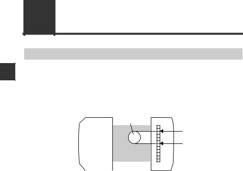
This unit receives laser light from the transmitter. The receiver uses a CCD (Charge Coupled Device) as the receiving detector. The CCD is a linear array of light receiving elements. When a target is placed between the transmitter and receiver, a shadow is caused on the receiver. By detecting the light to dark and dark to light transitions, the unit is able to measure those areas accurately.
For details, refer to "4-3 Setting the Measurement Sensitivity" (page 4-44).
Transmitter |
Receiver |
|
Object |
Edge
Edge
CCD 
1-2 |
IG-E |
|
1-1 Overview of the IG Series |
|
Specialized Measurement Modes |
|
|
You can select a suitable measurement mode according to the particular application. |
1 |
|
"1. Measurement mode" (page 4-8) |
|
|
Edge control/Positioning |
Outer diameter/Width measurement |
|
|
|
Use Before |
Light-shielding object |
|
|
A. Edge control/Positioning mode |
B. Outer diameter/Width measurement mode |
|
Inner diameter |
Transparent object Edge control/ |
|
|
Positioning |
|
C. Inner diameter |
|
D. Glass edge mode |
|
|
|
IG-E |
1-3 |

1-1 Overview of the IG Series
Center position measurement
1s
e U Before
E. Pin position measurement mode
Multiple diameter measurement
Pitch measurement |
F. Pin interval judgment mode
Measure the distance between |
specified edges. |
G. Pin diameter judgment mode
H. Specified edges interval measurement mode
1-4 |
IG-E |
1-1 Overview of the IG Series
Using the Expansion Units
The IG Series include main units (IG-1000, IG-1500) and expansion units (IG-1050, IG1550). By connecting the expansion unit to the main unit, the IG Series can be used for various purposes.
Calculation function
Tolerance is judged based on the calculated result (calculated value) of measurement value of two units of IG Series and the analog output can be performed.
"4-4 Calculation Function" (page 4-47)
Adding the measurement value
The diameter or width of a target that cannot be measured with one unit can be measured.
s |
1 |
e U Before
Subtracting the measurement value
The level of a target can be calculated.
Level to be measured
Interference prevention function
Mutual interference can be prevented between the additionally installed IG Series units.
"14. Interference prevention function (only for IG-1000/1500)" (page 4-40)
IG-E |
1-5 |
s |
1 |
e U Before
1-2 Checking the Package Contents
The following equipment and accessories are included in the package. Before using the unit, make sure that all items are included.
We have thoroughly inspected the package contents before shipment. However, in the event of defective or broken items, contact your nearest KEYENCE office.
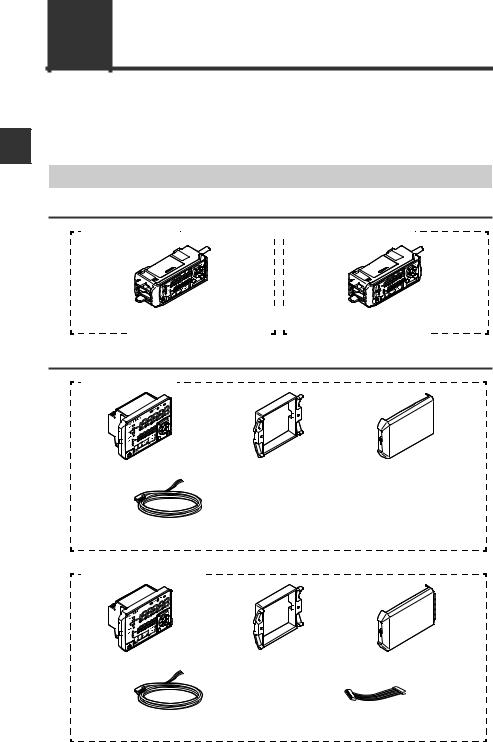
Sensor Amplifier
DIN rail mount type
IG-1000 (main unit) 


 IG-1050 (expansion unit)
Sensor amplifier x 1 |
|
|
|
|
|
|
|
|
|
|
|
|
|
Sensor amplifier x 1 |
|||||||||||||||||||||||||||||||||||||||||
|
|
||||||||||||||||||||||||||||||||||||||||||||||||||||||
Instruction manual x 1 |
|
|
|
|
|
|
|
|
|
|
|
|
|
|
|
|
|
|
|
|
|
|
|
|
|
|
|
|
|
||||||||||||||||||||||||||
|
|
|
|
|
|
|
|
|
|
|
|
|
|
|
|
|
|
|
|
|
|
|
|
|
|
|
|
|
|||||||||||||||||||||||||||
|
|
|
|
|
|
|
|
|
|
|
|
|
|
|
|
|
|
|
|
|
|
|
|
|
|
|
|
|
|
|
|
|
|
|
|
|
|
|
|
|
|
|
|
|
|
|
|
|
|
|
|
|
|
|
|
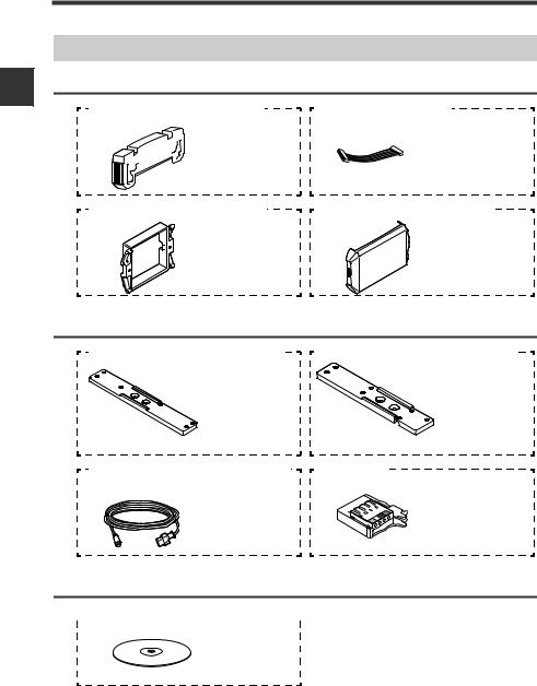
Panel mount type
IG-1500 (main unit)
Sensor amplifier x 1 |
Panel mounting |
Front protection |
|
tool x 1 |
cover x 1 |
Power/Input-output cable (2 m) x 1 |
|
Instruction manual x 1 |
(12 cores) |
|
|
IG-1550 (expansion unit)
Sensor amplifier x 1 |
Panel mounting |
Front protection |
|
tool x 1 |
cover x 1 |
Input-output cable (2 m) x 1 |
|
Expansion cable |
(8 cores) |
|
(50mm) x 1 |
1-6 |
IG-E |
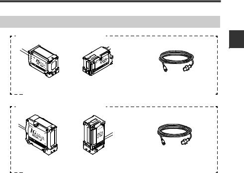
1-2 Checking the Package Contents
Sensor Head
IG-010 (Measurement range: 10 mm)
Transmitter x 1 |
|
Receiver x 1 |
Sensor head connection cable (2 m) |
||||||||||||||||||||||||||||||||||||||||||||||||||||||||||||||||||||
|
|
|
|
|
|
|
|
|
|
|
|
|
|
|
|
|
|
|
|
|
|
|
|
|
|
|
|
|
|
|
|
|
|
|
|
|
|
|
|
|
|
|
x 2 |
||||||||||||||||||||||||||||
|
|
|
|
|
|
|
|
|
|
|
|
|
|
|
|
|
|
|
|
|
|
|
|
|
|
|
|
|
|
|
|
|
|
|
|
|
|
|
|
|
|
|
|
|
|
|
|
|
|
|
|
|
|
|
|
|
|
|
|
|
|
|
|
|
|
|
|
|
|
|
|
IG-028 (Measurement range: 28 mm)
s |
1 |
e U Before
Transmitter x 1 |
|
Receiver x 1 |
Sensor head connection cable (2 m) |
||||||||||||||||||||||||||||||||||||||||||||||||||||||||||||||||||||
|
|
|
|
|
|
|
|
|
|
|
|
|
|
|
|
|
|
|
|
|
|
|
|
|
|
|
|
|
|
|
|
|
|
|
|
|
|
|
|
|
|
|
x 2 |
||||||||||||||||||||||||||||
|
|
|
|
|
|
|
|
|
|
|
|
|
|
|
|
|
|
|
|
|
|
|
|
|
|
|
|
|
|
|
|
|
|
|
|
|
|
|
|
|
|
|
|
|
|
|
|
|
|
|
|
|
|
|
|
|
|
|
|
|
|
|
|
|
|
|
|
|
|
|
|
IG-E |
1-7 |
1 |
Use Before
1-2 Checking the Package Contents
List of Optional Parts
For Sensor amplifier
OP-26751 (For IG-1000/IG-1050) |
OP-35361 (For IG-1550) |
End unit |
Expansion cable |
x 2 |
(300 mm) x 1 |
OP-4122 (For IG-1500/IG-1550) |
OP-87076 (For IG-1500/IG-1550) |
Panel mounting |
Front protection |
tool x 1 |
cover x 1 |
For Sensor head |
|
IG-TB01 (Mounting bracket for the IG-010) |
IG-TB02 (Mounting bracket for the IG-028) |
Hexagon socket |
Hexagon socket |
head bolt x 6 |
head bolt x 7 |
(M3 x 5 mm, with |
(M3 x 5 mm, with |
washer) |
washer) |
Mounting bracket x 1 |
Mounting bracket x 1 |
OP-87056 (2 m)/OP-87057(5 m)/ |
OP-84338 |
OP-87058 (10 m)/OP-87059 (20 m) |
|
Sensor head |
Sensor head |
connection |
cable connector |
cable x 1 |
x 2 |
Others

 IG Configuration Software (IG-H1)


x 1
To use the IG configuration software (IG Configurator), "RS-232C Communication Unit DLRS1A" is required. For details on DL-RS1A, refer to "RS-232C Communication Unit DLRS1A User’s Manual".
1-8 |
IG-E |
1-3 Part Names and Functions |
|
|
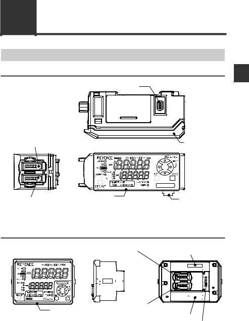
Sensor Amplifier Unit |
1 |
|
DIN rail mount type (IG-1000/IG-1050) |
||
s |
||
Expansion unit connector*1 |
|
e U Before
Sensor head connector (Transmitter side) |
Amplifier control |
|
unit cover |
Amplifier control unit |
Expansion unit |
|
Sensor head connector (Receiver side) |
||
connector*2 |
||
|
*1 When shipped from the factory, the protective cover for expansion slots is installed. *2 It is not installed on the main unit (IG-1000).
Panel mount type (IG-1500/IG-1550)
|
|
|
|
|
|
|
|
Sensor head connector (Transmitter side) |
|
|
|
|
|
|
|
Expansion unit connector |
|
|||||||||||||||||||||||||||||||||||||||||||||||||||||||
|
|
|
|
|
|
|
|
|
|
|
|
|
|
|
|
|
|
|
|
|
|
|
|
|
|
|
|
|
|
|
|
|
|
|
|
|
|
|
|
|
|
|
|
|
|
|
(upper)*1 |
|
||||||||||||||||||||||||
|
|
|
|
|
|
|
|
|
|
|
|
|
|
|
|
|
|
|
|
|
|
|
|
|
|
|
|
|
|
|
|
|
|
|
|
|
|
|
|
|
|
|
|
|
|
|
|
|
|
|
|
|
|
|
|
|
|
|
|
|
|
|
|
|
|
|
|
|
|
|
|
|
Amplifier control unit |
Sensor head connector (Receiver side) |
|
|
|
Expansion unit connector (lower)*2 |
Power/Input-output cable connector
*1 It is not installed on the main unit (IG-1500).
*2 When shipped from the factory, the protective seal is attached.
IG-E |
1-9 |
|
1-3 Part Names and Functions |
||
|
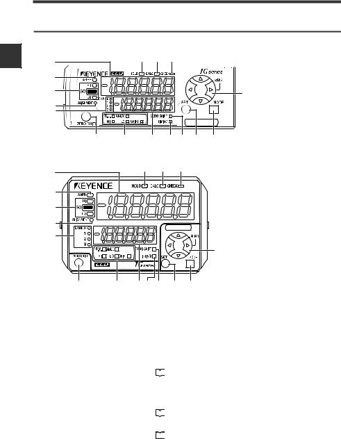
Amplifier control unit |
|
|
|
DIN rail mount type (IG-1000/IG-1050) |
||
s |
|
(16) (15) (14) |
|
1 |
(1) |
||
|
|||
e U Before
(2)
(3)
(4)
(5)
(13)
(6) |
(7) |
(8) |
(9) (10) (11) |
(12) |
Panel mount type (IG-1500/IG-1550)
(1) |
|
(16) |
(15) |
(14) |
|
|
|
|
|
(2) |
|
|
|
|
(3) |
|
|
|
|
(4) |
|
|
|
|
(5) |
|
|
|
|
|
|
|
|
(13) |
(6) |
(7) |
(8)(9)(10) |
(11) (12) |
|
|
Item |
|
Description |
|
(1) |
Main display |
Displays the judgment value (P.V.) and each setting item. |
||
|
|
|
|
|
(2) |
Laser emission indicator |
Lights on while the laser beams are emitted. |
||
|
|
|
|
|
|
|
Displays whether the judgment value (P.V.) is HIGH (over |
||
(3) |
judgment indicator |
the upper limit), GO (within the acceptable range) or LOW |
||
(below the lower limit) against the tolerance setting value. |
||||
|
|
|||
|
|
|
"3-6 Setting the Tolerance Setting Value" (page 3-11) |
|
|
|
|
||
|
|
|
|
|
|
|
Lights up when the optical axis is successfully aligned. |
||
(4) |
Optical axis alignment |
Align the optical axis when the target is not present and the |
||
indicator |
optical alignment indicator is off. |
|||
|
||||
|
|
|
"3-3 Optical Axis Alignment" (page 3-8) |
|
|
|
|
||
|
|
|
|
|
|
|
Displays a bank in use. |
||
(5) |
Bank indicator |
|
"3-8 Bank Function (Registering Multiple Tolerance |
|
|
||||
|
|
|
Setting Values)" (page 3-18) |
|
|
|
|
|
|
1-10 |
IG-E |
1-3 Part Names and Functions
|
Item |
|
Description |
|
|
|
Press this button to match the internal measurement value |
||
(6) |
Zero shift button |
(R.V.) to the shift target value. |
||
|
"3-7 Zero Shift Function (Shifting the Internal |
|||
|
|
|
||
|
|
|
Measurement Value (R.V.))" (page 3-16) |
|
|
|
|
|
|
(7) |
Sub display indicator |
Lights up according to the type of values displayed on the |
||
sub display. |
||||
|
|
|||
|
|
|
|
|
(8) |
Sub display |
Displays the internal measurement value (R.V.), analog |
||
output value and each setting (selection) item. |
||||
|
|
|||
|
|
|
|
|
|
|
Lights up while the timing input is ON when the timing input |
||
(9) |
Timing input indicator |
(external input) is set to Level. Lights on approx. 0.5 sec. |
||
when the timing input is set to Edge and the timing input is |
||||
|
|
|||
|
|
turned ON. |
||
Lights up approx. 0.5 sec. when the zero shift button is (10) Zero shift indicator pressed and released, or the zero shift input (external
input) is turned ON.
(11) SET button
Used to automatically adjust the setting values when setting each item.
(12) MODE button
Used when setting each item, starting/ending the setting or moving items.
(13) Arrow button
Used when selecting setting items, changing display contents on the sub display, etc.
Lights up when the edge check output is ON.
(14) Check indicator
|
|
|
"9. Edge check function" (page 4-31) |
|
|
|
|
|
|
Lights up when calculation is in process using the |
|
(15) |
Calculation indicator |
calculation function. |
|
|
|
|
"4-4 Calculation Function" (page 4-47) |
|
|
|
|
|
|
|
|
(16) |
Hold indicator |
Lights up when the judgment value (P.V.) is held. |
|
|
"5. Hold function" (page 4-20) |
||
|
|
|
|
s |
1 |
e U Before
IG-E |
1-11 |

s |
1 |
e U Before
1-3 Part Names and Functions
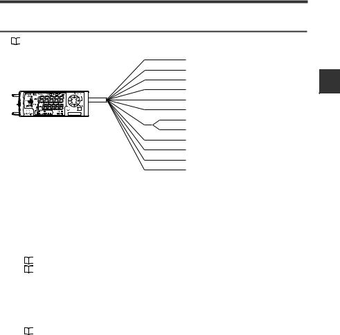
Sensor Head Unit
IG-028/IG-010
|
|
Transmitter |
Receiver |
|
(7) Laser transmitter |
(6) Laser receiver |
|
|
(1) Optical axis |
|
(5) Position Monitor |
|
alignment indicator |
|
|
|
|
(4) Optical axis |
|
|
[ALIGNMENT] |
|
|
|
(2) Power indicator |
(8) Top |
alignment indicator |
|
[ALIGNMENT] |
||
|
[POWER] |
||
|
|
|
|
|
|
(9) Bottom |
|
|
|
(3) Connector |
|
|
|
(8) Top |
|
|
|
(9) Bottom |
|
|
Item |
|
Description |
|
|
Lights up when the optical axis is successfully aligned. |
|
(1) |
Optical axis alignment |
Align the optical axis when the target is not present and the |
|
(4) |
indicator |
optical alignment indicator is off. |
|
|
|
"3-3 Optical Axis Alignment" (page 3-8) |
|
(2) |
Power indicator |
Lights on when the power is supplied to the sensor head. |
|
(3) |
Connector |
Connect with the sensor head connection cable. |
|
|
|
Used to check the laser light-receiving status, measured |
|
(5) |
Position monitor |
parts, etc. |
|
"17. Position monitor" (page 4-41)
(6) |
Laser receiver |
Receives laser beams. The surface is covered with the |
|
glass. |
|||
|
|
||
|
|
|
|
(7) |
Laser transmitter |
Emits laser beams. The surface is covered with the glass. |
|
|
|
|
|
(8) |
Top |
Distinguishing between top and bottom is important when |
|
|
|
installing the sensor head or measuring. |
|
(9) |
Bottom |
Note |
Use the transmitter and receiver in combination |
|
of the same serial number. If they are used in |
|
combination of the different serial numbers, the |
|
operation and accuracy are not guaranteed. The |
|
serial number is attached on top of the |
|
transmitter and receiver. |
Transmitter Receiver
SERIAL No. |
No. |
12345678 12345678
1-12 |
IG-E |

Installation and Connection |
2 |
This chapter describes precautions when installing and connecting |
|
the IG Series. |
2-1 |
Mounting and Wiring the Sensor Amplifier ........ |
2-2 |
2-2 |
Connecting and Mounting the Sensor Head....... |
2-8 |
IG-E |
2-1 |
2 |
Connectiontiona a llInnda s
2-1 Mounting and Wiring the Sensor Amplifier
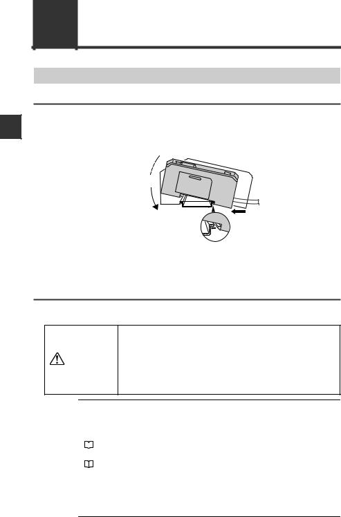
Mounting the Sensor Amplifier
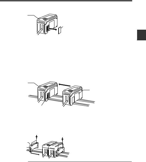
DIN rail mount type, main unit (IG-1000)
1 |
Align the claw at the bottom of the main body with the DIN rail. While |
pushing the main body in the direction of the arrow (1), slant it in the |
direction of the arrow (2).
(3)
|
(2) |
(1) |
|
|
|
2 |
To dismount the sensor, raise the main body in the direction of the arrow |
|
(3) while pushing the main body in the direction of the arrow (1). |
||
DIN rail mount type, expansion unit (IG-1050)
Several expansion units can be used in connection with the main unit. Up to 3 expansion units can be connected to one main unit.
•When connecting multiple amplifiers (expansion units), first check to make sure that the power is turned OFF to all of the main and expansion units. Connecting the units
CAUTION |
with the power turned ON may cause damage to the units. |
•Push the amplifiers (expansion units) as close as possible the main unit. Improper connections may damage the equipment.
Note |
• When connecting the expansion units, make sure to initialize the |
|
|
|
connected expansion units and set the output polarity. |
|
(1) When turning on the amplifier for the first time after connecting the |
|
|
|
sensor head |
|
|
"3-1 Operation When the Power is Turned on for the First Time" (page 3-2) |
|
|
|
|
(2) When performing the initial reset |
|
"3-5 Initial Reset (Initialize)" (page 3-10)
•Expansion units with different setting of output polarity (such as an NPN output expansion unit to a PNP output main unit) cannot be connected together.
•Expansion units of DIN rail mount type cannot be connected to the main unit of panel mount type.
2-2 |
IG-E |
|
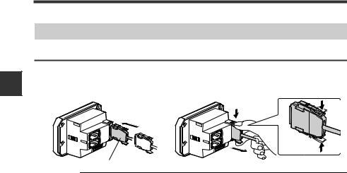
2-1 Mounting and Wiring the Sensor Amplifier |
1 |
Remove the expansion protective cover from the IG-1000 (main unit). |
Main unit |
|
|
Connector cover |
2 |
Install the amplifiers (expansion units) on the DIN rail. |
|
Refer to "DIN rail mount type (Main unit)" for details about how to mount. |
3 |
Push the expansion unit into the main unit connector until a clicking |
sound can be heard. |
|
|
The expansion unit additionally installed next to the main unit is referred to as |
|
expansion unit 1. Subsequent expansion units are referred to as expansion unit 2, |
|
expansion unit 3, etc. |
|
Main unit |
|
Expansion unit 1 |
|
Connecter |
4 |
Install the end units (OP-26751: 2 units in a set) (sold separately) on both |
sides of the amplifiers (main and expansion units). Secure the end units in |
place with screws on top (2 on each end unit).
The end units are mounted in the same way as the amplifiers.
End unit


 End unit
2 |
Connectiontiona a llInnda s
Note |
|
Fix the amplifiers securely using the end units (OP-26751: 2 units |
|
|
in a set) (sold separately) or commercially available DIN rail fixing |
|
|
tool to prevent the amplifiers from slipping the DIN rail or coming |
|
|
off from the DIN rail due to machine vibration. |
|
|
|
IG-E |
2-3 |
2-1 Mounting and Wiring the Sensor Amplifier
2 |
Connectiontiona a llInnda s
Panel mount type, main unit (IG-1500)
1 |
Make a hole on the panel to attach according to the size below. |
|||||||||||||||||||
When arranging lengthwise to attach |
When arranging widthwise to attach |
|||||||||||||||||||
|
+ 0.6 |
|
|
|
|
|
|
|
|
Min. 85mm |
||||||||||
|
|
|
|
|
|
45mm − 0 |
|
|
|
|
|
|
|
|
|
|
|
|
||
|
|
|
|
|
|
|
|
|
|
|
|
|
|
|
|
|
|
|||
|
|
|
|
|
|
|
|
|
|
|
|
|
|
|
|
|
|
|
|
|
|
|
|
|
|
|
|
|
|
|
|
|
|
|
|
|
|
|
|
|
|
|
|
|
|
|
|
|
|
|
45mm |
|
|
|
|
|
|
|
|
|||
|
|
|
|
|
|
|
|
|
+ 0.6 |
|
|
|
|
|
|
|
|
|
|
|
|
X mm |
|
|
|
|
|
|
− 0 |
|
|
|
|
|
|
|
|
||||
|
|
|
|
|
|
|
|
|
|
|
|
|
|
|
|
|
|
|||
|
|
|
|
|
|
|
|
|
|
|
|
|
|
|
|
|
|
|
|
|
|
|
|
|
|
|
|
|
|
|
|
|
|
|
|
|
|
|
|
|
|
|
|
|
|
|
|
|
|
|
|
|
|
|
|
|
|
|
||||
|
|
|
|
|
|
|
|
|
|
|
|
|
|
45mm + 0.6 |
|
|||||
|
|
|
|
|
|
|
|
|
|
|
|
|
|
|
− 0 |
|||||
|
• Panel thickness 1 to 6 mm |
|||||||||||||||||||
|
|
|
|
|
|
|
|
|
|
|
|
|
||||||||
|
• X=48 x (number of amplifiers) -3 |
|
|
|
|
|
|
|
|
|
|
|
|
|||||||
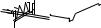
2 Insert the back side of amplifier to the hole of panel. |
||||||||||||||||||||
3 |
Arrange the panel mounting tool in the direction below, fix to the amplifier |
|||||||||||||||||||
from the back and attach the front protection cover to the amplifier. |
||||||||||||||||||||
Front protection cover
Sensor amplifier
Panel
Panel mounting tool
To remove the panel mounting tool, widen the claws at both ends of the panel mounting tool using a slotted screwdriver, etc. and remove alternately.
2-4 |
IG-E |
2-1 Mounting and Wiring the Sensor Amplifier
Panel mount type, expansion unit (IG-1550)
Several expansion units can be used in connection with the main unit. Up to 3 expansion units can be connected to one main unit.
•Turn OFF the power before connecting the expansion cable. Inserting or removing the cable with the power
CAUTION |
turned on may cause damage to the units. |
•Be sure to completely connect the expansion cable. Improper connections may damage the equipment.
Note |
• When connecting the expansion units, make sure to initialize the |
|
|
|
connected expansion units and set the output polarity. |
|
(1) When turning on the amplifier for the first time after connecting the sensor head |
|
|
|
"3-1 Operation When the Power is Turned on for the First Time" (page 3-2) |
|
|
|
|
(2) When performing the initial reset |
|
"3-5 Initial Reset (Initialize)" (page 3-10)
•Expansion units with different setting of output polarity (such as an NPN output expansion unit to a PNP output main unit) cannot be connected together.
•Expansion units of panel mount type cannot be connected to the main unit of DIN rail mount type.
1Make holes on the panel to attach according to the number of amplifiers
(connected expansion units).
For the panel cutting size, refer to the "Panel mount type, main unit".
2Install the amplifiers (expansion units) on the panel.
For the amplifier mounting method, refer to the "Panel mount type, main unit".
3Connect the amplifier (main unit) and amplifier (expansion unit) using the expansion cable (50 mm) supplied with the expansion unit.
The expansion unit additionally installed next to the main unit is referred to as expansion unit 1. Subsequent expansion units are referred to as expansion unit 2, expansion unit 3, etc.
|
Main unit |
|
Expansion cable |
|
Expansion unit 1 |
Reference |
When arranging the amplifiers side by side, the expansion cable of 300 mm |
|
(OP-35361) is necessary. |
IG-E |
2-5 |
2 |
Connectiontiona a llInnda s
2-1 Mounting and Wiring the Sensor Amplifier
Sensor Amplifier Wiring
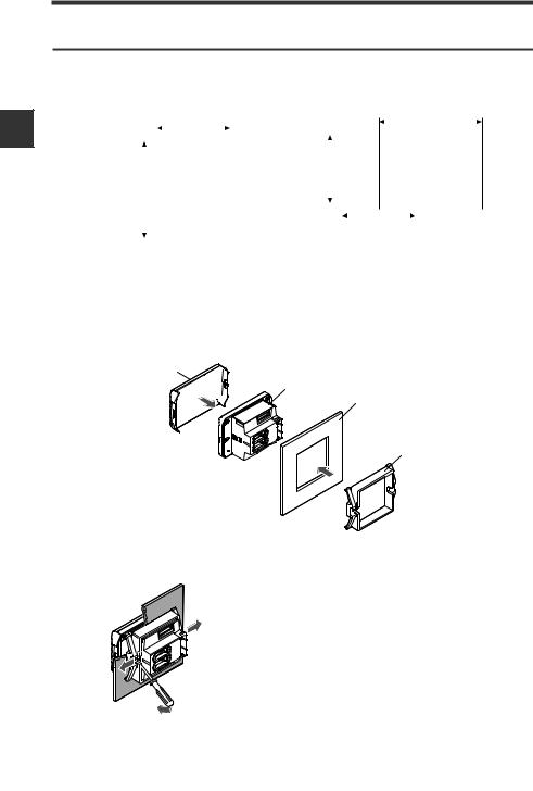
Connecting power/Input-output cable (only for panel mount type)
2 |
Connect the power/input-output cable to the panel mount type main unit and connect the input-output cable to the expansion units.
To attach |
To remove |
Connectiontiona a llInnda s
Power/Input-output cable
Note |
|
• The number of core wire of power/input-output cable for the main unit |
|
|
is 12, and the number of core wire of Input-output cable for the |
|
|
expansion units is 8. |
|
|
• Power for the expansion units is supplied from the main unit. |
|
|
• If the input-output is not used for the expansion units, cut the cable at |
|
|
the connector base or terminate the wires properly for future use. |
|
|
|
2-6 |
IG-E |
2-1 Mounting and Wiring the Sensor Amplifier
Power/Input-output cable
"Output Circuit Diagram" (page 5-4)
Brown *1
10 to 30 VDC
Blue *1
0 V
Black
HIGH judgment output
White
LOW judgment output
Gray
GO judgment output
Green
Edge check output
Light blue*1 Orange *2
Analog output +
Shield *2
Analog output GND
Pink *3
External input 1 (Zero shift input)
Yellow *3
External input 2 (Reset input)
Pink/Purple *3
External input 3 (Timing input)
Purple *3
External Input 4 (Gain input)
*1 IG-1050/IG-1550 (expansion units) do not have brown, blue or light blue wires. Power is supplied to the expansion units through IG-1000/IG-1500 (main unit).
*2 The analog output can be set to either "When the power is turned on for the first time" or "When performing the initial reset".
•Not used (OFF)
•0 to 5 V
•-5 to 5 V
•1 to 5 V
•4 to 20 mA
"3-1 Operation When the Power is Turned on for the First Time" (page 3-2)
"3-5 Initial Reset (Initialize)" (page 3-10)
*3 The external input can be selected among the following in addition to the above.
•Bank A input
•Bank B input
•Laser emission stop input
•Not used (OFF)
Gain input can be selected only for the external input 4.
"11. External input" (page 4-33)
2 |
Connectiontiona a llInnda s
IG-E |
2-7 |
2-2 Connecting and Mounting the Sensor Head
2 |
Connectiontiona a llInnda s
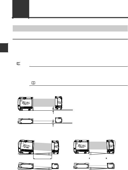
Mounting the Sensor Head
Notes for mounting
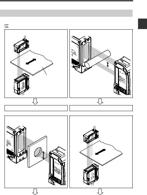
If the mounting distance between the transmitter and receiver is as follows, the optical axis alignment is not necessary when mounting within the "parallel acceptable range" and "tilt acceptable range".
•IG-010 : 3 to 500 mm
•IG-028 : 50 to 500 mm
If the distance is beyond the above ranges, align the optical axis after mounting.
"3-3 Optical Axis Alignment" (page 3-8)
Note |
The minimum object for detection, |
linearity and |
temperature |
|
characteristics in the specifications are |
values when |
mounting the |
sensor head within the "parallel acceptable range" and "tilt acceptable range".
"5-1 Specifications" (page 5-2)
Parallel acceptable range
Transmitter |
within ±0.5 |
mm |
Receiver |
Transmitter |
within ±0.5 |
mm |
Receiver |
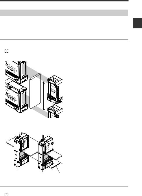
Tilt acceptable range
Tilt of transmitter |
Tilt of receiver |
Transmitter |
A |
Receiver |
Mounting distance
|
|
|
|
|
|
Transmitter |
|
C |
Receiver |
||
|
|
|
|
|
|
Mounting distance
Transmitter |
B |
Receiver |
Transmitter |
D |
Receiver |
||
|
|
|
|
|
|
|
|
Mounting distance |
A |
|
|
B |
|
C |
D |
500 mm or less |
within ±0.05° |
|
within ±0.05° |
|
within ±1° |
within ±2° |
|
|
|
|
|
|
|
|
|
100 mm or less |
within ±0.2° |
|
within ±0.2° |
|
within ±1° |
within ±2° |
|
|
|
|
|
|
|
|
|
2-8 |
IG-E |
Loading...