


 Loading...
96M00261
User's Manual
Operator Interface Panel
KV-D20

Safety Precautions
This instruction manual describes the operation and function of the Operator Interface Panel. Read this manual carefully to ensure safe use and maximum performance from your KV-D20.
Symbols
The following symbols alert you to important messages. Be sure to read these messages carefully.

 WARNING

 CAUTION
Note:
Failure to follow instructions may lead to injury. (electric shock, burn, etc.)
Failure to follow instructions may lead to product damage.
Provides additional information on proper operation.
General Precautions
•At startup and during operation, be sure to monitor the functions and performance of the KV-D20.
•We recommend that you take substantial safety measures to avoid any damage in the event a problem occurs.
•Do not open or modify the KV-D20 or use it in any way other than described in the specifications.
•When the KV-D20 is used in combination with other instruments, functions and performance may be degraded, depending on operating conditions and the surrounding environment.
•Do not use the KV-D20 for the purpose of protecting the human body.
2

Note to User
When using the NEW KV Series in the following conditions or environments, be sure to use the NEW KV Series with sufficient margin regarding the rating and functions, take appropriate safety precautions such as fail-safe, and contact our sales personnel if any questions arise.
•Use in conditions or environments not described in this manual
•Use for nuclear power control, railway facilities, air service facilities, vehicles, combustion devices, medical equipment, amusement machines, safety equipment, etc.
•Use for applications where large effects are predicted to be given on human lives and properties and safety is especially requested.
Restriction on Acquiring the CE Marking
■ Restriction to be compatible with EMC directives
•When using a relay output type unit (whose model name ends with "R"), connect spark killers having the appropriate withstand voltage against the load to the output terminals in parallel to contacts (because the unit discharges when a relay contact becomes open and noise is generated). In our experiments, we use the following models of spark killers.
XEB0101 0.1 F-10 Ω manufactured by OKAYA DENKI SANGYO
The following 1-turn ferrite core is added to the AC power input circuit of the KV40AR/T, the KV-24AR/T and to the DC power input circuit of the KV-40DR/T.
ZCAT3035-1330 manufactured by TDK
Note: The contents above do not by themselves ensure that the entire machine manufactured in accordance with the above contents is compatible with EMC directives.
You must judge by yourself whether or not the entire machine is compatible with EMC directives because compatibility may change depending on the component configuration, wiring and location inside of the machine.
■ Restriction on compatibility with low-voltage directives (IEC-1010-1)
•Use insulated type crimp-style terminals.
•For wiring materials, use lead wires whose sheath is 0.4 mm or more.
•The NEW KV Series is allowed to be installed in a vertical position only. (Spacers for expansion units are not available.)
•Be sure to use the NEW KV Series inside the control panel.
3

Warranty
Our products are thoroughly inspected before shipment. However, in the event of a malfunction, contact your nearest KEYENCE office.
KEYENCE will replace or repair any defective parts free of charge for one year from the date of shipment from the factory. However, we shall not be responsible for any failure resulting from improper use, negligence, natural disaster or fire.
Caution
•No part of this manual may be reprinted or reproduced in any form or by any means without the prior written permission of KEYENCE CORPORATION.
•The content of this manual is subject to change without notice.
•KEYENCE has thoroughly checked and reviewed this manual. Please contact the sales office listed at the end of this manual if you have any questions or comments regarding this manual or if you find an error.
•KEYENCE assumes no liability for damages resulting from the use of the information in this manual, item 3 above notwithstanding.
•KEYENCE will replace any incomplete or incorrectly collated manual.
All company names and product names in this manual are registered trademarks or trademarks of their respective owners.
4

5

Contents
1 |
Before Operation |
|
8 |
|
1.1 |
Checking Package Contents ................................................................. |
8 |
|
1.2 |
Part Names and Functions .................................................................... |
9 |
|
1.3 |
Details about the KV-D20 .................................................................... |
10 |
|
|
General specifications ....................................................................... |
10 |
|
|
Functional specifications .................................................................... |
10 |
|
|
Dimensions ........................................................................................ |
11 |
|
1.4 |
Installation and Environment .............................................................. |
12 |
|
|
Use environment ................................................................................ |
12 |
|
|
Panel mounting .................................................................................. |
13 |
|
1.5 |
Inspection and Maintenance ............................................................... |
14 |
|
|
Inspection .......................................................................................... |
14 |
|
|
Maintenance ...................................................................................... |
14 |
|
Overview and Operation |
15 |
|
2 |
|||
|
2.1 |
Use Examples for the KV-D20 ............................................................. |
15 |
|
2.2 |
Connection with the KV Series ........................................................... |
16 |
|
|
Connection ......................................................................................... |
16 |
|
|
Precautions ........................................................................................ |
16 |
|
2.3 |
Overview of the KV-D20 ...................................................................... |
17 |
|
|
Switching the display mode ............................................................... |
17 |
|
|
Overview of each display mode ......................................................... |
18 |
|
|
Assignment of relays/DM ................................................................... |
19 |
|
|
Other functions .................................................................................. |
20 |
|
|
Precautions about screen change function ........................................ |
23 |
|
2.4 |
Operator Mode ..................................................................................... |
25 |
|
|
Screen selection in operator mode .................................................... |
25 |
|
|
Operator screen ................................................................................. |
26 |
|
|
Direct access screen ......................................................................... |
34 |
|
|
KV-I/O monitor screen ....................................................................... |
35 |
|
|
Switch comment screen ..................................................................... |
36 |
|
|
Lamp comment screen ...................................................................... |
36 |
|
|
Screen change permission in operator mode .................................... |
37 |
|
2.5 |
Device Mode ......................................................................................... |
38 |
|
|
Device mode ...................................................................................... |
38 |
|
|
Operation example for device mode .................................................. |
40 |
|
2.6 |
System Mode ........................................................................................ |
42 |
|
|
System mode ..................................................................................... |
42 |
6

3 Examples of Ladder Programs |
43 |
|
3.1 |
Basic Ladder Programs ....................................................................... |
43 |
|
Before creating ladder programs ....................................................... |
43 |
|
Basic ladder programs ....................................................................... |
44 |
3.2 |
Examples of Ladder Programs ........................................................... |
51 |
|
Example of displaying user messages .............................................. |
51 |
|
Example of displaying messages with titles ....................................... |
53 |
|
Example of position control ................................................................ |
54 |
|
Example of frequency counter ........................................................... |
57 |
|
Example of 24-bit high-speed counter ............................................... |
60 |
|
Example of cam switch function ........................................................ |
62 |
4 Appendix |
|
66 |
4.1 |
Troubleshooting ................................................................................... |
66 |
4.2 |
Available Character List ...................................................................... |
70 |
4.3 |
Comment Draft Sheet .......................................................................... |
71 |
7

1.Before Operation
1.Before Operation
This section includes the names, functions, and details of the KV-D20 and information required before starting operation.
1 1.1 Checking Package Contents
The KV-D20 package includes the following components. Before using the KV-
D20, check that all components have been included in the package.
7 |
6 |
5 |
4 |
|
|
|
|
|
|
3 |
2 |
1 |
|
||
|
|
|
|
|
0 |
KV-D20 Display |
Modular cable (2.5 m) |
|
OP-26487 |
Mounting fixture (2 pcs.)
8
1. Before Operation
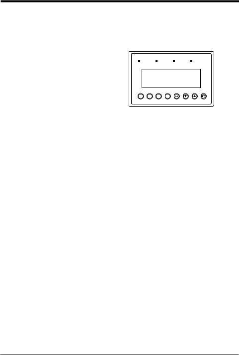
1.2Part Names and Functions
This section describes the part names and functions of the KV-D20.
|
|
|
1. Customized lamps |
|
|
|
2. LCD display |
|
|
|
|
|
|
1 |
||||||||||||||
|
|
|
|
|
|
|
|
|
|
|
|
|
|
|
|
|
|
|
|
|
|
|
|
|
|
|
|
|
|
|
|
|
|
|
|
|
|
|
|
|
|
|
|
|
|
|
|
|
|
|
|
|
|
|
|
|
|
|
|
|
|
|
|
|
|
|
|
|
|
|
|
|
|
|
|
|
|
|
|
|
|
|
|
|
|
|
|
|
|
|
|
|
|
|
|
|
|
|
|
|
|
|
|
|
|
|
|
|
|
|
|
|
|
|
|
|
|
|
|
|
|
|
|
|
|
|
|
|
|
|
|
|
|
|
|
|
|
|
|
|
|
|
|
|
|
|
|
1 |
|
|
|
2 |
|
|
|
3 |
|
|
|
|
4 |
|
|
||||||||||
|
5. Communication port |
|
|
|
|
|
|
|
|
|
|
|
|
|
|
|
|
|
|
|
|
|
|
|
|
|
||
|
|
|
|
|
|
|
|
|
|
|
|
|
|
|
|
|
|
|
|
|
|
|
|
|
||||
|
(rear side) |
|
|
|
|
|
|
|
|
|
|
|
|
|
|
|
|
|
|
|
|
|
|
|
|
|
|
|
|
6. Bit guide |
|
|
|
|
|
|
|
|
|
|
|
|
|
|
|
|
|
|
|
||||||||
|
|
|
|
|
|
|
|
|
|
|
|
|
|
7 6 5 4 3 2 1 0 |
|
|
|
|
||||||||||
|
|
|
|
|
|
|
|
|
|
|
|
|
|
|
|
|
||||||||||||
|
|
|
|
|
|
|
|
F1 |
F2 |
|
|
F3 |
F4 |
|
|
|
|
|
|
|
||||||||
|
|
|
|
|
|
|
|
|
|
|
|
|
|
|||||||||||||||
|
|
|
|
|
|
|
|
|
|
|
|
|
|
|
|
|
|
|
|
|
|
|
|
|
|
|
|
|
|
|
|
3. Customized switches |
4. Setting operation switch |
||||||||||||||||||||||||
|
|
|
|
|
|
|
|
|
|
|
|
|
|
|
|
|
|
|
|
|
|
|
||||||
No. |
Name |
|
|
|
|
|
|
|
|
|
|
|
|
|
Function |
|
|
|
|
|
|
|
||||||
|
|
|
|
|
||||||||||||||||||||||||
|
Customized |
|
Assigned to special utility relays. The LED illuminates when the |
|
||||||||||||||||||||||||
1 |
|
corresponding relay turns on. |
|
|
|
|
|
|
|
|||||||||||||||||||
lamps |
|
|
|
|
|
|
|
|
||||||||||||||||||||
|
|
(Lamp 1: 2504, Lamp 2: 2505, Lamp 3: 2506, Lamp 4: 2507) |
|
|
||||||||||||||||||||||||
|
|
|
|
|||||||||||||||||||||||||
2 |
LCD display |
|
Displays comments of up to 20 characters described in ladder |
|
||||||||||||||||||||||||
|
programs, or displays all devices used in the KV unit. |
|
|
|||||||||||||||||||||||||
|
|
|
|
|||||||||||||||||||||||||
|
|
|
|
|
||||||||||||||||||||||||
|
Customized |
|
Assigned to special utility relays. The relay turns on when the |
|
||||||||||||||||||||||||
3 |
|
corresponding switch is turned on. |
|
|
|
|
|
|
|
|||||||||||||||||||
switches |
|
|
|
|
|
|
|
|
||||||||||||||||||||
|
|
(F1: 2500, F2: 2501, F3: 2502, F4: 2503) |
|
|
||||||||||||||||||||||||
|
|
|
|
|||||||||||||||||||||||||
4 |
Setting operation |
|
Change screen display. |
|
|
|
|
|
|
|
||||||||||||||||||
switches |
|
|
|
|
|
|
|
|
||||||||||||||||||||
|
|
|
|
|
|
|
|
|
|
|
|
|
|
|
|
|
|
|
|
|
|
|
|
|
|
|
|
|
|
|
|
|
|
|
|
|
|
|
|
||||||||||||||||||
|
Communication |
|
Used for connection with the KV unit. |
|
|
|
|
|
|
|
||||||||||||||||||
5 |
|
Connected to the communication port of the KV basic unit with |
|
|||||||||||||||||||||||||
port |
|
the supplied cable (OP-26487). |
|
|
|
|
|
|
|
|||||||||||||||||||
|
|
|
|
|
|
|
|
|
||||||||||||||||||||
|
|
|
Also supplies the drive power supply to the KV-D20. |
|
||||||||||||||||||||||||
|
Bit guide |
|
Shows the corresponding number of each bit on the KV-I/O |
|
||||||||||||||||||||||||
6 |
|
monitor screen, the operator screen, or the 8-bit ON/OFF |
|
|||||||||||||||||||||||||
|
|
|
indication in the device mode. |
|
|
|
|
|
|
|
||||||||||||||||||
9

1. Before Operation
1.3Details about the KV-D20
This section describes the general specifications, functional specifications, and dimensions of the KV-D20.
General specifications
1
Item |
Specification |
|
Power supply |
Supplied from the communication port of the KV (5 VDC) |
|
voltage |
||
|
||
|
|
|
Current |
5 VDC, 180 mA max. |
|
consumption |
(60 mA max. when converted for 24 V) |
|
Surrounding air |
0 to +50°C |
|
temperature |
||
|
||
Relative humidity |
35 to 85% |
|
Ambient storage |
-20 to 70°C |
|
temperature |
||
|
||
|
1500 VAC for 1 min. |
|
Withstand voltage |
(between power terminal and I/O terminals, and |
|
|
between external terminals and housing) |
|
|
1500 V p-p min., Pulse width: 1 s and 50 ns |
|
Noise immunity |
(Noise generated by noise simulator), |
|
|
Conforming to IEC standard (IEC61000-4-2/-3/-4/-6) |
|
Vibration |
10 to 55 Hz, 1.5 mm max. double amplitude in X, Y and Z |
|
directions, 2 hours respectively |
||
|
||
|
|
|
Insulation |
50 MΩ min. |
|
(Between power terminal and housing, measured with |
||
resistance |
||
500 VDC megohmmeter) |
||
|
||
Environmental |
No excessive dust or corrosive gases |
|
restrictions |
||
|
||
Weight |
Display: Approx. 160 g, Communication cable: Approx. 60 g, |
|
Special mounting fixture: Approx. 30 g (2 pcs.) |
||
|
||
|
|
|
Structure |
Built-in panel, IP-65F only for the front operation panel |
Functional specifications
Item |
Specification |
|
|
|
|
Connectable units |
One KV-D20 for one KV basic unit |
|
|
|
|
Display |
20 digits x 4 lines, Blue-negative type backlit LCD |
|
|
|
|
Character size |
2.95 mm x 4.75 mm (5 x 7 dots) |
|
|
|
|
Customized |
4 switches assigned to special utility relays |
|
switch |
(F1: 2500, F2: 2501, F3: 2502, F4: 2503) |
|
Setting operation |
▲▼ |
|
switch |
||
|
||
Customized lamp |
4 Red LEDs, assigned to special utility relays |
|
(Lamp 1: 2504, Lamp 2: 2505, Lamp 3: 2506, Lamp 4: 2507) |
||
|
10
1. Before Operation
Dimensions
■ KV-D20
Panel thickness: 1.2 to 3.0 mm
1
75 |
67 |
112 |
5 |
34 |
133 |
|
|
(Including mounting fixtures) |
|
|
■ Panel cutout
|
145 |
68 +10 |
|
105 +10 |
83 |
11

1.Before Operation
1.4Installation and Environment
Use environment
1

 CAUTION
This section describes the panel mounting method and precautions for installation.
This section describes environment, location, and wiring precautions for the KVD20.
■ Locations
Avoid installing the KV-D20 in the following locations:
•Locations in which the KV-D20 may be subjected to direct sunlight.
•Locations in which the surrounding air temperature drops below 0°C or exceeds 50°C.
•Locations in which the relative humidity drops below 35% or exceeds 85%.
•Locations in which condensation occurs due to sudden temperature drops.
•Locations in which there are corrosive or flammable gases.
•Locations exposed to dust, salt, metal particles, or greasy fumes.
•Locations in which the KV-D20 may be directly subjected to vibration or impact.
•Locations in which water, oil, or chemicals may splash the KV-D20.
•Locations in which a strong magnetic or electric field is generated.
Install the KV-D20 as far as possible from radio transmitters and receivers. Radio waves generated by the KV-D20 may cause noises on these devices.
■ Precautions for improving noise immunity
•Do not install the KV-D20 inside of a panel along with high-voltage equipment.
•Install the KV-D20 as far as possible from power lines.
•If the KV-D20 is installed near equipment that generates a strong electric or magnetic field (e.g. solenoids, choppers, etc.), install it as far as possible from the equipment.
•Precautions for operability and maintenance
To improve safety during operation and maintenance, install the KV-D20 as far as possible from high-voltage equipment or power equipment.
•Do not install the I/O signal lines in the same conduit as power lines or high voltage lines. Otherwise, generated noise may cause malfunctions.
If noise causes flicker on the display of the KV-D20, provide ferrite cores on the modular cable. (It is more effective to wrap the cable once around the ferrite core.)
Modular cable supplied with the KV-D20
Ferrite cores
12
2. Overview and Operation
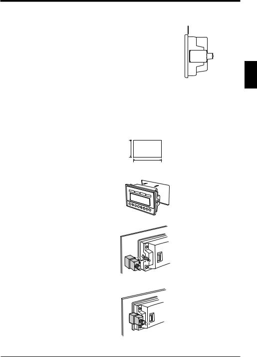
Panel mounting
■ Precautions
•Install the KV-D20 by holding the panel at the front and rear sides with the unit and mounting fixtures.
Available panel thickness: 1.2 mm to 3.0 mm

 1.2 to 3.0 mm
* If your panel has a thickness of 3.0 mm or more, contact your nearest KEYENCE
office listed at the back of this manual.
2
•To ensure maintainability, operability, and ventilation, keep as much distance as possible between the KV-D20 and the surrounding structure or components.
•Prevent the KV-D20 from being heated by the heat released by other devices.
•Install the KV-D20 as far as possible from devices that may generate arcs (e.g. electromagnetic switches, no-fuse circuit breakers, etc.).
■ Mounting method
1. Cut an opening with the following dimensions in the panel to mount the KV-D20.
68+10
105+10
2.Insert the KV-D20 through the opening from the front surface of the panel.
7 |
6 |
5 |
4 |
3 |
|
|
|
|
|
|
|
|
2 |
1 |
0 |
3. Secure the KV-D20 to the panel with the mounting fixtures.
4. Tighten the screws of the fixtures. [Tightening torque: 0.2 N•m (2 kgf•cm) max.]
13

2.Overview and Operation
1.5Inspection and Maintenance
Inspection
2
Maintenance
This section describes how to inspect and maintain the KV-D20.
The KV-D20 may cause malfunctions due to loose modular cable connectors or mounting fixtures during long-term use.
Be sure to regularly check the KV-D20 unit and connections. The major items to check are as follows:
•Are the modular cable connectors disconnected or loosened?
•Are the mounting fixtures of the KV-D20 detached or loosened?
Dust adheres to the KV-D20 during long-term use. Wipe the dust off using a clean dry cloth.
If dust or dirt adheres to a small part, wipe it off using a cotton swab.

 CAUTION Be sure to turn off the KV-D20 before inspection or maintenance.
14

2. Overview and Operation
2.Overview and Operation
2.1Use Examples for the KV-D20
This section includes examples of uses for the KV-D20.
As a handheld programmer
The KV-D20 allows you to change the KV series’ operating mode (RUN or PROGRAM) or to change the preset values of timers and counters without using the
KV-P3E(01) handheld programmer.
2
As a digital switch
Various values can be input with the KV-D20. You can directly change the values of desired devices without using ladder programs.
Moreover, the KV-D20 can be connected with a cable instead of the I/O unit, so that the amount of wiring and I/O points can both be reduced.
As a display unit
The KV-D20 can display the number of products or the tact time. Since the KV-D20 can be connected with a cable instead of the I/O unit, the amount of wiring and I/O points can both be reduced.
As a device to give instructions to workers
When using a rotating beacon, the occurrence of an error can be noted but the contents of the error, such as a clogged workpiece, missing workpiece, or product changeover, may often be unclear.
The KV-D20 features a user message function. By using the function, work efficiency can be greatly improved.
A beep function is also available to indicate errors with sound.
15
2. Overview and Operation
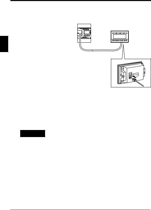
2.2Connection with the KV Series
Connection
2
Precautions

 WARNING
This section describes how to connect the KV-D20 with the KV Series.
Open the connector |
|
cover of the KV basic |
|
unit and connect the |
|
modular connector |
|
supplied with the KV- |
|
D20. (Either communi- |
|
cation port A or B can |
|
be used.) |
Modular cable (2.5 m) |
|
Insert the other end of the modular cable to the communication port at the rear of the KV-D20.
•Connecting/disconnecting the modular cable can be done at any time regardless of whether the KV unit is turned on or off.
•Both communication ports A and B can be used to connect the KV-D20. However, do not connect two KV-D20s at the same time.
•When connecting the KV-P3E(01) handheld programmer to a KV Series that is already connected to the KV-D20, set the mode selector switch of the KVP3E(01) to "PROGRAM" before connecting it. Do not connect the KV-P3E(01) to the KV series together with the KV-D20 for a long period of time.
•Never tie the modular cable together with or route it close to strong electrical lines or output lines. This will cause damage to the KV-D20.
•Prevent a strong force from being applied to the modular cable.
•Be sure to use the modular cable specified by KEYENCE (OP-26487, supplied with the KV-D20). Use of an unspecified cable may cause malfunctions.
•The modular cable cannot be extended.
16

2. Overview and Operation
2.3Overview of the KV-D20
The KV-D20 has three display modes: operator mode, device mode, and system mode. This section includes an overview of these modes.
Switching the display mode
The KV series has two operating modes: RUN and PROGRAM.
The KV-D20 allows changes among the operator mode, device mode, and system mode for the RUN and PROGRAM modes respectively.
RUN mode |
PROGRAM mode |
||
|
Operator |
|
2 |
|
|
Operator |
|
|
mode |
|
mode |
+ |
+ |
+ |
+ |
Device mode |
System mode |
Device mode |
System mode |
Customized switches F1 through F4 and customized lamps 1 through 4 can be used in all modes.
To lock the display screen, press the  and ▲ (▼) keys simultaneously for three seconds to set/reset the key-lock function.
Changes between display modes can be limited by setting special utility relays 2508 and 2509 and data memory DM1676.
Refer to "Screen change function" on page 22.
17

2. Overview and Operation
Overview of each display mode
This section includes an overview of the three display modes: operator mode, device mode, and system mode.
■ Operator mode ( page 25)
Normally, operators use this mode. It includes the following five screens:
|
• Operator screen ( page 26) |
|
Allows you to display five pages (20 lines/page) of devices by writing simple |
|
ladder programs. Contact comments that are entered with alphanumeric char- |
2 |
acters can also be displayed. Each device can be displayed along with various |
attributes. |
|
|
• Direct access screen ( page 34) |
|
|
|
This screen corresponds to the digital trimmer mode of the Access Window of |
|
the KV unit. Values in three DM (DM1677, DM1678, and DM1679) can be |
|
changed in real time. |
|
• KV-I/O monitor screen ( page 35) |
|
Allows simultaneous monitoring of two channels (8 bits x 4 lines) for the I/O |
|
status and unit connection information for the KV series I/O devices. |
|
• Switch comment screen ( page 36) |
|
Displays the contact comments for relays (2500 to 2503) assigned to four built- |
|
in customized switches (F1 to F4) of the KV-D20, provided that the comments |
|
are entered with alphanumeric characters. |
|
• Lamp comment screen ( page 36) |
|
Displays the contact comments for relays (2504 to 2507) assigned to four built- |
|
in customized lamps (Lamp 1 to Lamp 4) of the KV-D20, provided that the |
|
comments are entered with alphanumeric characters. |
■ Device mode ( page 38)
This mode corresponds to the device mode of the Access Window of the KV unit. Allows you to display or change all device values (The digital trimmer value cannot be changed.).
■ System mode ( page 42)
This mode corresponds to the system mode of the Access Window of the KV unit.
Allows you to switch the KV unit between RUN and PROGRAM modes using the
KV-D20. However, LOAD/SAVE functions using EEPROM are not available.
18

2. Overview and Operation
Assignment of relays/DM
In the KV series, special utility relays 2500 through 2513, DM1580 through 1599, and DM1670 through 1699 are the devices relevant to the KV-D20. The devices are assigned as follows:
■ Special utility relays used for the KV-D20
Relay No. |
Function |
|
|
|
|
|
|
2500 |
Pressing F1 (Customized switch 1) turns on this relay. |
|
|
2501 |
Pressing F2 (Customized switch 2) turns on this relay. |
|
|
|
|
|
2 |
2502 |
Pressing F3 (Customized switch 3) turns on this relay. |
|
|
|
|
||
|
|
|
|
2503 |
Pressing F4 (Customized switch 4) turns on this relay. |
|
|
|
|
|
|
2504 |
Lamp 1 illuminates when this relay is ON. |
|
|
|
|
|
|
2505 |
Lamp 2 illuminates when this relay is ON. |
|
|
|
|
|
|
2506 |
Lamp 3 illuminates when this relay is ON. |
|
|
|
|
|
|
2507 |
Lamp 4 illuminates when this relay is ON. |
|
|
|
|
|
|
|
Change between operator mode and device mode: |
|
|
2508 |
OFF: Disable, ON: Enable |
|
|
|
The initial setting disables changes to device mode. |
|
|
|
|
|
|
|
Change between operator mode and system mode: |
|
|
2509 |
OFF: Disable, ON: Enable |
|
|
|
The initial setting disables changes to system mode. |
|
|
|
|
|
|
|
Display language for system messages: |
|
|
2510 |
OFF: English, ON: Japanese (katakana) |
|
|
|
The initial setting is English. |
|
|
|
|
|
|
2511 |
Beep setting: A beep sounds when this relay is ON. |
|
|
|
|
|
|
|
Reset setting of KV-D20 |
|
|
2513 |
Used to immediately reflect a change such as screen change permission. |
|
|
Resets the KV-D20 when this relay is ON. Turns off automatically when the |
|
|
|
|
|
|
|
|
KV-D20 is reset. |
|
|
2515 |
User message display (DM1950): ON: Enable, OFF: Disable |
|
|
|
|
|
|
Note: To set special utility relay 2513 to reset the KV-D20, turn on (SET) 2513 for one scan as shown below. The relay is automatically turned off after the KV-D20 is reset.
|
XXXX |
1000 |
1000 |
2513 |
|
|
||||
|
|
|
|
DIFU |
|
|
|
SET |
|
xxxx: Condition (Trigger input) |
|
|
|
|
|
|
|
|
|
|
|
|
|
|
|
|
|
|
|
|
|
|
■ Data memory used for the KV-D20
DM No. |
Function |
|
|
|
|
DM1580 to |
Device number to be displayed (first line to 20th line) |
|
DM1599 |
||
|
||
|
|
|
DM1670 to |
Reserved for system |
|
DM1675 |
||
|
||
|
|
|
DM1676 |
Permits screen change in operator mode. |
|
|
|
|
DM1677 to |
Used for direct access screen |
|
DM1679 |
||
|
||
|
|
|
DM1680 to |
Attributes of displayed device (first line to 20th line) |
|
DM1699 |
||
|
||
|
|
|
DM1950 |
Specifies user message display devices. |
|
|
|
19
2. Overview and Operation
Other functions
This section describes other functions of the KV-D20.
User message function
2
This function corresponds to the user message function of the Access Window of the KV unit. The Access Window displays numeric values only, but the KV-D20 displays comments as well.
Messages are displayed with 32 characters (16 characters x 2 lines).
The Access Window displays the desired number stored in DM1950 when a certain relay turns on. However, the KV-D20 displays the contact comment for the device specified with the value stored in DM1950, in the same manner as the operator screen.
Note that although the KV unit is running, the Access Window does not display the correct value while the user message is displayed.
To cancel the user message, press the  key. (Pressing the
  key is effective even while the key-lock function is set.)
Type of device to be displayed
Device |
Operand value |
DM1950 setting value |
|
|
|
Timer |
T (0 to 249) |
20000 to 20249 |
|
|
|
Counter |
C (0 to 249) |
21000 to 21249 |
|
|
|
CTC |
(0 to 3) |
22000 to 22003 |
|
|
|
CTH |
(0, 1) |
23000 to 23001 |
|
|
|
Temporary data memory |
TM (0 to 31) |
24000 to 24031 |
|
|
|
Data memory |
DM (0 to 1999) |
30000 to 31999 |
|
|
|
Relay |
RLY (0 to 17915) |
40000 to 57915 |
|
|
|
|
|
|
Note: Do not enter a value in DM1950 other than those above.
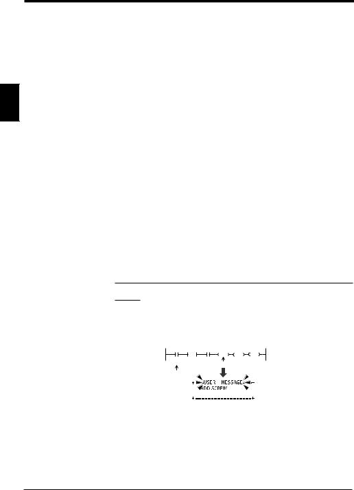
Example
When the value specifying a certain relay is stored in DM1950 and the relay turns on, the comment for the relay is displayed on the KV-D20 screen.
The following ladder program displays the message "Add screws" when relay 0001 turns on.
Specified
relay |
1000 |
1000 #40001 |
DM1950 |
2515 |
0001 |
DIFU |
LDA |
STA |
SET |
|
|
|
|
"ADD SCREW" Instruction to display comment for relay 0001
Contact comment |
[RLY0001 turns on] |
||||
|
|
|
|||
|
|
|
|
|
|
|
|
|
|
|
|
|
|
|
|
|
|
|
|
|
|
|
|
|
|
|
|
|
|
|
|
|
|
|
|
|
|
|
|
|
|
Note 1: To enter a space to the left of a contact comment, input "~" (swung dash) at the left end of the comment with the LADDER BUILDER for KV. Spaces without "~" at the left end will be ignored. Please note when "~" is used in the middle of a contact comment, it is displayed as " ".
Note 2: Contact comments can be displayed only when the LADDER BUILDER for KV Ver. 1.5 or later is used and the compression transfer of contact comments is not selected.
20

2. Overview and Operation
Note 3: Even the contact comments for ladder programs created with LADDER BUILDER for KV Ver. 1.0x or KV-LADDER can be displayed on the KV-D20 after being transferred to the KV unit with the LADDER BUILDER for KV Ver. 1.5 or later.
Note 4: "Not transfer" is initially set as the contact comment transfer setting of the LADDER BUILDER for KV Ver. 1.5 or later. To display contact comments on the KV-D20, enable the contact comment transfer setting with the LADDER BUILDER for KV Ver. 1.5 or later.
Refer to the NEW KV Series User's Manual "Chapter 6 Software-Windows [KV-H6WE2]" on page 195.
When a system error occurs |
2 |
The KV-D20 monitors only the communication status with the KV series.
When a system error occurs or communication is disabled in the KV unit, the KV-
D20 displays the message "TIME OUT ERROR".
Display language selection
The KV-D20 allows language selection from "English" or "Japanese" for the messages defined by the system of the KV series. The initial setting is English (Refer to the table below).
To switch the display to Japanese, turn on special utility relay 2510.
English |
Japanese |
Description |
PRESET |
|
Preset value of a timer or counter |
|
|
|
INC/DEC |
|
Increment (decrement) quantity for direct access screen |
|
|
|
NO PROGRAM |
|
Nothing (or value 0) is specified to DM1580 or later data |
|
memory. |
|
|
|
|
OUT OF RANGE |
|
Preset value for DM1580 or later data memory is out of |
|
available range. |
|
|
|
|
UNUSED |
|
Unused timer/counter/high-speed counter is specified to |
|
DM1580 or later data memory. |
|
|
|
Change to PROG
Screen changes from RUN to PROG in system mode
(Exit RUN)
Change to RUN
Screen changes from PROG to RUN in system mode
(Exit PROG)
Example
Display in system mode
RUN mode
English display |
Japanese display |
PROG mode
English display |
Japanese display |
21
2. Overview and Operation
Beep function
The KV-D20 features a beep function to provide an audio signal for workers.
The beep sounds while special utility relay 2511 is turned on.
2511 is OFF. |
2511 is ON. |
Beep
2
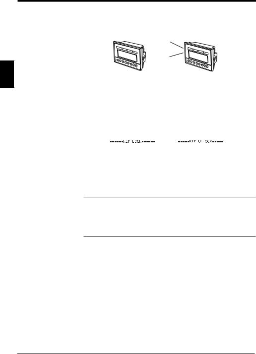
Key-lock function
The key-lock function is used to lock the display screen.
When the key-lock function is set, the current screen is locked regardless of the display screen mode or status.
To set or reset the key-lock function, press the  and ▲ (▼) keys simultaneously for three seconds.
The key-lock setting is retained even when the KV-D20 is turned off once and on again.
Key-lock |
|
Key-unlock (reset) |
|
|
|
Screen retention function
When the KV-D20 is turned on again, it shows the last screen displayed before the power was turned off.
However, the decimal/hexadecimal notation setting in device mode is not retained. Decimal notation is used when the KV-D20 is turned on again.
Note 1: The status of the KV-D20 is retained by the KV unit.
Note 2: The status of the KV-D20 is retained only for the memory backup period of the KV unit.
Note 3: To retain the status longer, select "SAVE" in the system mode of the
Access Window of the KV unit.
Refer to "LOAD mode and SAVE mode" on page 4.
Screen change function
Setting special utility relay 2508 to "ON" enables switching between the operator mode and the device mode. Setting special utility relay 2509 to "ON" enables switching between the operator mode and the system mode.
Setting each bit of DM1676 to "ON" enables the screen change in the operator mode. The initial setting (DM1676 = #00000) only allows switching between the operator, switch comment, and lamp comment screens.
When changing the current mode (screen) is disabled during operation, the setting becomes effective after the current mode (screen) is changed to another mode (screen). To activate the setting immediately, turn on special utility relay 2513. The mode is switched to the operator mode when the setting of special utility relays 2508 or 2509 is changed. The mode is switched to the next available mode when the setting of data memory DM1676 is changed.
22
Loading...