


SJ-M400
Table of contents
 Loading...
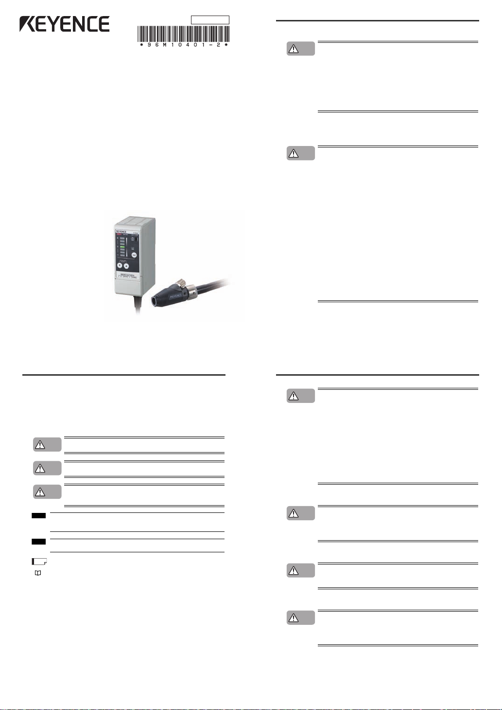
1
Before using this Compact Static Eliminator, be sure to
thoroughly read this Instruction Manual.
After you are finished with this Instruction Manual, be
sure to store it in a safe place for quick reference.
High-performance Micro Static Eliminator
Instruction Manual
SJ-MSJ-M400
96M10401
Preface
This document describes handling, method of operation and precautions when using the Compact
Spot-type Static Eliminator SJ-M 400 Series. Before youstart to use the SJ-M 400 Series, be sure to
thoroughly read this document in order to make full use and safely use its functions.
Store this document in asafe place so that you can ret
rieve it whenever necessary.
■ Symbols
This manual uses the following symbols to alert you to important information.
Be sure to read this information.
Failure to follow these instructions may lead to death or serious injury.
Failure to follow these instructions may lead to injury.
Failure to follow these instructions may lead to product damage (product
malfunction, etc.).
Provides additional information on precautions and restrictions that must be
followed in operation.
Provides additional information on proper operation.
Indicatesuseful information or information that aidsunderstanding of text descriptions.
Indicatesa reference item or page to be referred to in this manual or aseparate manual.
DANGER
WARNING
CAUTION
Important
Note
Tip
Safety Precautions
■ General Precautions
• At start up and during operation, be sure to monitor the functions and
performance of the SJ-M Series.
• We recommend that you take substantial safety measures to avoid any
damage in the event that a problem occurs.
• Do not modify the SJ-M Serie s or use it in any way other than described in
the specifications. The functions and performance of products used or
modified in this way cannot be assured.
• When the SJ-M Series is used in combination with other instruments,
functions and performance may be degraded, depending on operating
conditions and the surrounding environment. Use the SJ-M after fully
studying the effect of combined use with other instruments.
• Do not use the SJ-M Series for the purpose of protecting the human body.
■ SJ-M Series Handling Precautions
The SJ-M Series isa high-voltage product that is not designed in an explosion-proof structure. Pay
attention to the following when using the SJ-M Series.
•
To prevent electric shock and to ensure accurate static elimination, be sure
to connect a Class D ground (maximum resistance of 100 Ohms).
•
The power cable supplied with the exclusive power supply (SJ-U2) is a 125 V
rated power cable. When connecting a power supply that exceeds this power
rating to the SJ-M Series, the user must prepare a power cable having
adequate voltage rating. If a power cable that does not meet the voltage
rating is used, this may cause electric shock, fire or malfunction.
•
Do not use this product in locations where there is the risk of ignition or
explosion from flammable solvents or dirt and dust.
•
High voltage is applied to this product. Prevent it from being splashed with
water, oil, or flammable solvents. Failure to do so may cause insulation
breakdown, which will result in electric shock or malfunction.
•
Do not bring your fingers, tools, wire or other metallic objects near this
product. Doing so may cause electric shock or malfunction.
•
If the SJ-M Series is used in an airtight location, the generated ozone may be
harmful. Be sure to ventilate the area when using the SJ-M Series.
•
Do not use this product in locations where sudden changes in temperature
or condensation are likely to occur.
•
Do not operate this product with wet hands. Doing so may cause electric
shock.
•
Before starting inspection or maintenance, be sure to turn the power OFF.
Failure to do so might result in electric shock or malfunction.
•
During maintenance, do not directly touch the electrode probe. Doing so may
cause personal injury.
•
If any malfunction is observed in this product, immediately turn it OFF, and
contact your nearest agent. You should never repair this product yourself.
Doing so may cause electric shock or malfunction.
•
Take soundproofing measuressuch as wearing earplugs when using the
SJ-M Series.
CAUTION
WARNING
• Do not to uch the electrode probe with a tool or other hard object. Damage to
the electrode probe will prevent static elimination performance from being
fully demonstrated, and cause accidents or malfunction.
• When this product is used for a long period of time, the electrode probe
become dirty due to the adhesion of dust and dirt. If the ion level alarm
indicator or condition alarm indicator lights, clean the electrode probe. If the
product is used with the electrode probe in a dirty or dusty state, the static
elimination performance can no longer be fully demonstrated, resulting in
accidents or malfunction. We recommend periodically cleaning the
electrode probe (as a guideline, once every two weeks in a regular operating
environment though this depends on the installation conditions).
• Do not drop or subject this product to shock. Doing so might result in
accident or malfunction.
• Use this product for static elimination only. Do not use it for other purposes.
• When installing the SJ-M Ser ies, observe the minimum bending radius of all
provided cables. Also,
do not install
the SJ-M with the cab
les deformed by
staples or other objects. Doing so might cause the SJ-M to malfunction.
■ Power Supply Precautions
• Use a DC power supply with rated 24 V output.
• Noise applied to the power supply may cause this product to malfunction. If
this happens, install an insulated transforme r.
• When using a switching regulator, be sure to connect a Class D ground to
the Frame Ground terminal.
■ Grounding Precautions
• To ensure safety and appropriate static elimination, be sure to ground this
product.
• Be sure to connect a Class D ground (maximum resistance of 100 Ohms).
■ Air Purge Function Precautions
• Be sure to use an air pressure of 0.7 MPa or less.
• Be sure to supply clean or dry air of temperature –20°C or more through a
filter of mesh size about 0.01μm. Moisture or oil contained in the air or
nitrogen may cause discharge inside the Static Elimination Head, which
may result in accidents or malfunction.
CAUTION
CAUTION
CAUTION
CAUTION
2
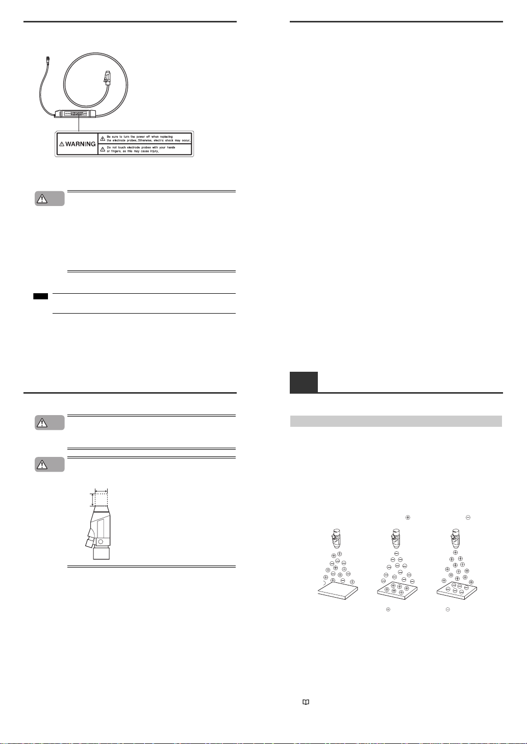
■ SJ-M Series Warning label
A WARNING label is affixed on the SJ-M Series to ensure safety. Read the description on this
WARNING label to ensure correct use of the SJ-M Series.
■ Installation Precautions
Avoid installing the SJ-M Series in the following locations as this may cause
accidents.
• Locations directly subject to vibration and shock
• Locations subject to ambient temperature outside of the 0°C to +40°C range
• Locations subject to ambient humidity outside of the 35 to 65%RH range
(condensation not allowed)
• Locations subject to sudden changes in temperature
• Locations subject directly to blasts from air conditioners
• Locations subject to volatile or flammable substance, solvents or corrosive
gases
• Locations subject to large amounts of dirt, and dust, salt, iron and oil smoke
• Locations that may be spl
ash
ed with water, oil or chemical mist
• Locations where strong magnetic and electrical fields are generated
■ About Warm-up
After turning the SJ-M Series ON, leave it for about 20 minutes to allow the ion
balance to stabilize.
WARNING labels in Japanese, German, French, Italian and Chinese (Simplified) are provided.
Use them as necessary.
CAUTION
Note
■ Other Precautions
•
Be sure to read the WARNINGS and CAUTIONS described in each of the
items in this Instruction Manual.
•
This Static Eliminator has a built-in EEPROM. Do not turn the Static
Eliminator OFF during the setup.
Install the tip of the SJ-M040 paying attention to the following point.
●Install the Static Elimination Head away from the wall or surrounding
objects.
CAUTION
CAUTION
20 mm or more
10 mm
or more
Precautions on Regulations and Standards
■ CE Marking
Keyence Corporation has confirmed that this product complies with the essential requirements of the
applicable EC Directive, based on the following specifications.
Be sure to consider the following specifications when using this product in the Member State of
European Union.
● EMC Directive(2004/108/EC)
• Applicable standard EMI: EN61326-1 (evaluated according to EN55011 Group 1, Class A)
EMS: EN61326-1
•Be sure to provide a ground when installing the SJ-M.
•The length of cable (power lead and I/O leads) must be less than or equal to 30m.
•Attach a one-loop ferrite core onto the High-voltage Cable Unit and pass the connector cable once
through the core.
•The following ferrite core is recommended:
SFC-10 made by KITAGAWA
INDUSTRIES CO,LTD.
Remarks:
These specifications do not give any
gua
rantee that the end-product with this product incorporated
complies with the essential requirements of EMC Directive. The manufacturer of the end-product is
solely responsible for the compliance on the end-product itself according to EMC Directive.
● Low-Voltage Directive (2006/95/EC)
• Applicable standard: EN61010-1
•Overvoltage categor yI
•Use this product under pollution degree 2.
•Use the power supply for the SJ-M Series, that satisfies the requirements of the Limited Power
Source specifications stipulated in EN60950-1 and cer ti fied by European third-party certification
organization, or a Keyence Corporation AC adapter (SJ-U2). The specifications of the AC adapter
(SJ-U2) are as follows
.
When connecting to an SJ-U2, be sure to use a power cable compliant with European standards.
Applicable standard: EN60950-1
Overvoltage categor yII
Pollution degree 2
•Be sure to provide a ground when installing the SJ-M Series.
1-1 Features of the SJ-M Series
This section describes an outline of the functions, the features of the SJ-M Series.
Outline of the SJ-M Series
■ Pulse AC method
The SJ-M Seriesuses a pulse AC method that generates + and – chargedair ions from asingle
electrode probe. This system ensuresa maximum ion level per unit time, which in turn high-speed static
elimination. The SJ-M Series also automatically controls the level of + and – ions generated matched to
the chargedstate of the target obje
ct. This
enables high-speed and high-precision static elimination
suited to installation conditions.
■ I.C.C. (Ion Current Control) method
This control method calculates the charged level of the target object by sensing the state of ion current
that arises due to the potential difference between the electrode on the Static Elimination Head and
GND. Optimum static elimination matched to the state of the target object can be performed by rapidly
supplying the optimum ions suited to t
he polarity and charged level of the target object.
■ Ion monitor functions
●
Charge monitor
The integrated ion monitor allows you to learn how much the target object is chargedby + or – ions.
This monitor also allows you to confirm at a glance how static elimination is being performed.
● Ion level monitor
The ion level currently being generated by the Static Elimination Head is monitored atall times so that
drops in the generated ion level can be diagnosed on the unit. The generated ion level is indicated by
LEDs and an alarm can be output when the generated ions fall below a certain level. This allows you to
monitor the influence of a dirty electrode probe in advance.
"Ion Monitor Functions" (page 8)
Regular state
Target object in
non-charged state
Elimination of ions
from target object
Elimination of ions
from target object
Target object
charged
Target object
charged
3
1-1
Features of the SJ-M Series
■ Alarm output functions
●
Alarm output functions
An indicator blinks and an alarm signal is output, for example, when internal circuits are damaged or
abnormal discharging occurs. When an alarm signal is output, generation of ions is forcibly stopped.
● Ion level alarm output function
An indicator lights and an alarm signal is output when the level of generated ions drops due to a dirty
electrode probe, for example.
● Condition alarm output function
An indicator lights and an alarm signal is output when static elimination performance is impaired.
"Alarm Output Functions" (page 8)
■ Abnormal discharge detection function
Abnormal discharge caused by condensation on the electrode probe tip or adhesion of debris is
detected. When abnormal discharge is detected, ion generation is forcibly stopped to prevent trouble at
an early stage.
"Abnormal Discharge Detection Function" (page 8)
■ Ion balance adjustment function
The ion balance zero point can be fine-adjusted.
"3. Adjusting ion balance" (page 7)
■ Static elimination stop function
Static elimination can be turned ON/OFF with the device still powered. This is achieved by
disconnecting the trigger input and 0V terminals on the Controller Unit (I/O terminal section) or by
holding down the two ion-balance adjustment keyssimultaneously for about three seconds.
"Static Elimination Stop Function" (page 8)
■ Air purge function
Dirt can be prevented from sticking to the electrode probe on the SJ-M040 by attaching a tube to the air
duct and supplying clean or dry air. This also extends the static elimination range.
"Air Purge Function" (page 8)
1-2
Checking the Contents of the Package
The package contains the following components and accessories. Before you start using the SJ-M
Series, make sure that the package contains everything that it issupposed to contain. A Replacement
Electrode Unit and other accessories are available as options.
"List of Options" (page 12)
Package Contents
Options
Before using this Compact Static Eliminator, be sure to
thoroughly read this Instruction Manual.
After you are finished with this Instruction Manual, be
sure to store it in a safe place for quick reference.
High-performance Micro Static Eliminator
Instruction Manual
SJ-MSJ-M400
Controller Unit (SJ-M400)Static Elimination Head (SJ-M040)
Instruction Manual
WARNING labels (Japanese, German, French,
Italian and Chinese (Simplified)) *
* Use as necessary.
Earth lead
Replacement Electrode Unit for SJ-M040
(OP-84383)
For details of the AC cable, contact the
KEYENCE sales office in your district.
Extension cable SJ-C3
Up to 3 cables can be connected.
AC Adapter SJ-U2
1-3 Names and Functions of Parts
This section describes the names and functions of parts on the SJ-M Series.
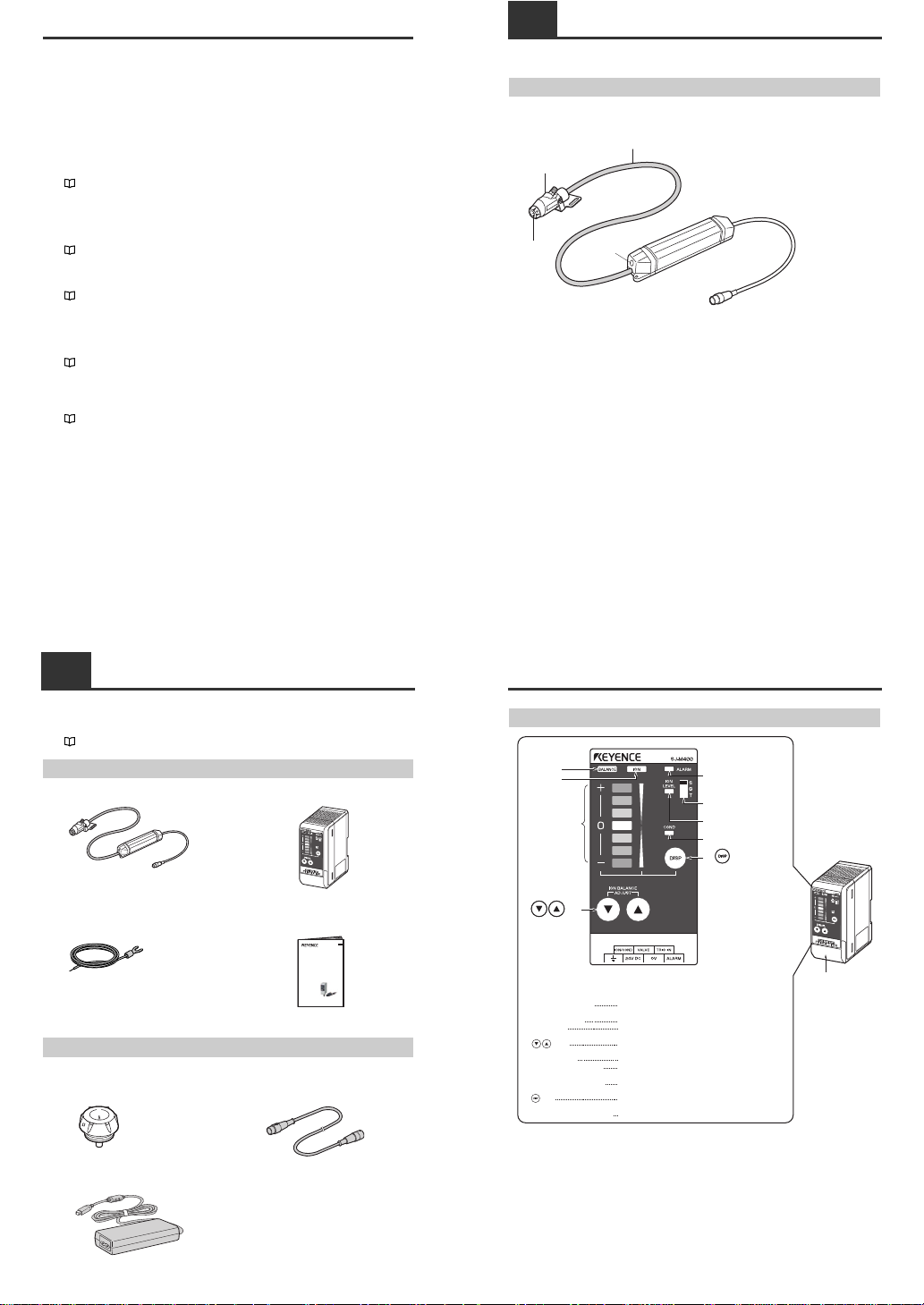
Static Elimination Head
● SJ- M040
(1) Electrode probe
Ion charge is emitted from the tip of this probe.
(2) Mounting fixture
Used to attach the static elimination head.
(3) High-voltage cable
Ambient operating temperature: 0 to +40°C
Minimum bending radius: 30 mm
(4) Drive unit
Operates the static elimination head and manages itssetup information.
(2)
(3)
(4)
(1)
1-3
Names and Functions of Parts
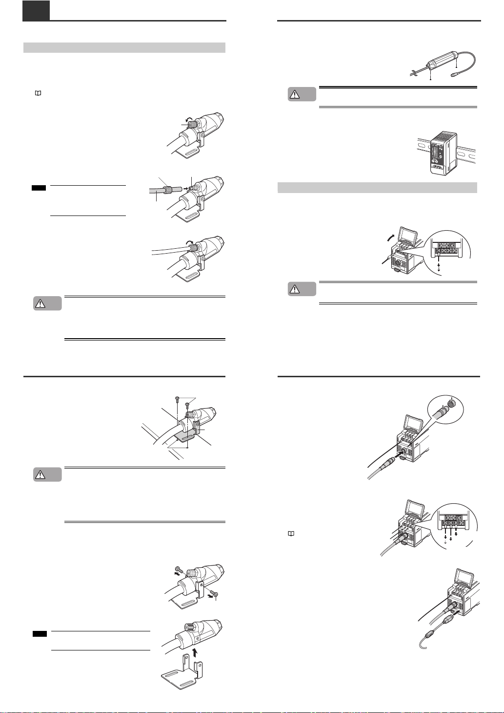
Controller Unit (operation/display section)
Enlarged view of display section
Terminal plate cover
Lights when the charged level of the target object is
displayed.
Lights when the ion emission level is being displayed.
Indicates the charged level of the target object.
Also, indicates the ion emission level.
Used for adjusting the ion balance and for selecting setting
items.
Lights when an alarm occurs.
Lights when the ion emission level has fallen below the set
value due to dirt or wear of the electrode probe.
Lights when the charged level of the target object is high
and static cannot be completely eliminated.
Used for determining setting items and for switching the
display.
Used for selecting the operation mode.
Ion balance
indicator
Ion level
indicator
Ion monitor
keys
key
Alarm indicator
Operation mode selector
switch
Ion le
v
el alarm indicator
Condition alarm indicator
Ion balance indicator
Ion level indicator
Ion monitor
keys
Alarm indicator
Ion level alarm indicator
Condition alarm indicator
key
Operation mode selector switch
(1)
(2)
(3)
(4)
(5)
(9)
(6)
(7)
(8)
(1)
(2)
(3)
(4)
(5)
(6)
(7)
(8)
(9)

4
1-3
Names and Functions of Parts
Controller Unit (I/O terminal section)
■ Input circuit diagram
■ Output circuit diagram
Number
Name Function
(1)
Condition/ion level alarm
output terminal
Outputs when static elimination performance is influenced by an
unstable operating environment or when the ion emission level drops.
(2) Valve output terminal Outputs the ON/OFF signal for the valve.
(3) Trigger input terminal
Static elimination can be turned ON/OFF by shorting this terminal with
(6).
(4) Ground terminal
Be sure t
o connect a Class D ground (maximum resistance of 100
Ohms).
(5) DC power terminal 24 VDC ±10%
(6) 0V terminal 0V for power and 0V for I/O
(7) Alarm output terminal Outputs when an alarm occurs. (N.C.)
(1)
(4) (5) (6) (7)
(2) (3)
+24V
3kΩ
INPUT (3)
0V (6)
Input a no-voltage contact (relay, etc.)
or NPN open collector to INPUT and 0V.
[ (3) (trigger input)]
OUT
DC40V
100mA
0V (6)
Open collector output
[ (2) (valve output), (1) (condition/ion level alarm output), (7) (alarm output)]
2-1 Before Installation
This section describes the static elimination performance of the SJ-M400 Series.
Before you install the SJ-M400 Series, fully calculate the distance between the Static Elimination Head
up to the target object and the time required for static elimination.
About Static Elimination Performance
The following showsa typical example where static is eliminated from an aluminum plate (20 pF) 150 x
150 mm square charged to +1000 V by the SJ-M400 Series.
■ Static elimination area
The following graphsshow the relationship between the time required for eliminating static from a target
object charged between +1000 to +100 V and the distance from the charged object up to the Static
Elimination Head.
No air
50100150
100
50
100
150
1.0 sec
200 mm
200 mm
200
300
400
500 mm
0.5 sec
5.0 sec
10 sec
23 Hz Air flow rate 20 N /min (pressure 0.06 MPa)
50100150 50
100
150
200 mm
200 mm
200
400
600
800 mm
0.5 sec
5.0 sec
2.0 sec
10 sec
1.0 sec
23 Hz Air flow rate 60 N /min (pressure 0.18 MPa)
50100150 50
100
150
200 mm
200 mm
200
400
600
800
1000 mm
0.5 sec
2.0 sec
1.0 sec
5.0 sec
23 Hz Air flow rate 230 N /min (pressure 0.7 MPa)
50100150 50
100
150
200 mm
200 mm
200
400
600
800
1000 mm
0.5 sec
2.0 sec
1.0 sec
5.0 sec
2-1
Before Installation
■ Appropriate static elimination method
Pay attention to the following points to ensure thatstatic elimination is performed appropriately.
Static elimination cannot be performed accurately at locations where the target object is
touching a metallic body (grounded body).
Eliminate static from the target object at locations where it is not directly touching metallic bodied
(grounded body).
Static will be eliminated from only the surface of the insulated body (board, etc.) that is facing
the Static Elimination Head.
When eliminating static from both sides of a target object, install two SJ-M Series as one SJ-M Series
must be i
nstalled on either side of the target object.
Install the Static Elimination Head so that it can be easily accessed, for example, for
replacement of parts and cleaning.
Installation Precautions
■ Installation site
Install the tip of the SJ-M040 paying attention to the following point.
●Install the Static Elimination Head away from the wall or surrounding
objects.
Insulating matMetal
Board
Board
Note
CAUTION
20 mm or more
10 mm
or more
2-1
Before Installation
■ Interference
The Static Elimination Head may not function properly if there is a conductor (grounded body) located
nearby or if two or more units are used close to each other. In such an installation, refer to the figure
below and maintain the indicated distance between the conductor (grounded body). If a conductor
(grounded body) is located inside the distances indicated below, adjust usin
g the ion balance manual
setup.
"3. Adjusting ion balance" (page 7)
When two SJ-M Series units are used, refer to the figures below, and install the units so that the
following distances are maintained between the two Static Elimination Heads.
70 mm or more
100 mm or more
100 mm or more
100 mm or more
150 mm or more
150 mm or more
5
2-2 Connection and Installation
This section describes how to connect and install the Static Elimination Head and Controller Unit.
Installing the SJ-M Series
Install the SJ-M Series at locations where static electricity is generated or is likely to be generated.
■ Installing the air supply tube
To use the air purge function, install anair supply tube to the air duct before securing the static
elimination head.
"Air Purge Function" (page 8)
1 Remove the tube fixing screw.
Turn the tube fixing screw attached at the air duct of
the static elimination head with your fingers to
remove it.
2 Connect the air supply tube to the air duct.
Pass the tube through the tube fixing screw and
then attach it completely to the air duct.
3 Secure the tube to the air duct with the tube fixing screw.
Tighten the tube fixing screw securely with your
fingers.
• Be sure to limit the air press ure to 0.7 MPa. Exceeding this limit may cause
accidents or malfunction.
• Be sure to use clean air, dry air as the air for supplying to the Static
Elimination Head. Moisture or oil contained in the air or nitrogen may cause
discharge inside the Static Elimination Head, which may result in accidents
or malfunction.
Tube fixing screw
Tube fixing screw
Tube
Air duct
Use Nylon or Urethane tube with a
6-mm outer diameter and 4-mm
inner diameter as the air supply
tube.
Note
CAUTION
2-2
Connection and Installation
■ Installing the Static Elimination Head
Adjust the angle of the static elimination head to
ensure proper installation. Tap M4 screw holes at
appropriate locations and secure the mounting
fixture with M4 screws.
When installing the SJ-M Series, observe the minimum bending radius of all
provided cables. Also, do not install the SJ-M Series with the cables deformed
by staples or other objects. Doing so might cause the SJ-M Series to
malfunction
When bending the cable frequently with the SJ-M Series in Gun mode, make
the cable's bending radius at least 5 times larger than the minimum bending
radius.
This value does not guarantee limitless number of bending times.
■ Detaching the mounting fixture from the head
The mounting fixture can be detached from the static elimination head.
1 Remove the M3 screws from the static elimination head.
Unscrew the M3 screws on both sides of the static
elimination head with a Phillips screwdriver to remove
them.
2 Detach the mounting fixture from the static elimination head.
M4 screws
Mounting
fixture
M4 tap
CAUTION
M3 screw
M3 screw
Keep the removed M3 screws and mounting
fixture safe so that they don't get lost.
Note
2-2
Connection and Installation
■ How to install the drive unit
Prepare mounting holes where the drive unit is being installed. Use M4 screws for installation.
(Tightening torque: 1 Nm or less)
The screws for installing the drive unit must be prepared
separately.
Make a space of 30 mm or more around the drive unit. Otherwise, the unit
may be damaged.
■ Installing the Controller unit
Mount the Controller Unit on the DIN rail.
Connecting Cables
When you have finished installing the Static Elimination Head, connect the ground lead, Static
Elimination Head connector cable and power supply.
■ Connecting the ground lead
Open the terminal plate cover on the Controller
Unit, and connect the ground lead to the GND
connection terminal.
Be sure to connect a Class D ground (maximum
resistance of 100 Ohms).
To prevent electric shock and to ensure accurate static elimination, be sure
to connect a Class D ground (maximum resistance of 100 Ohms).
M4 tap
CAUTION
Be sure to connect
a Class D ground
(maximum resistance
of 100 Ohms).
WARNING
2-2
Connection and Installation
■ Connecting the cable
Connect the Static Elimination Head
connector cable to the Controller Unit.
Connect this cable with the power
turned OFF.
When installing the Controller Unit
away from the Static Elimination
Head, use the optional extension
cable (SJ-C3). Up to 3 cables can be
connected.
■ Connecting the power supply
Connect the power supply according to either
of the following methods.
24 VDC power supply
Connect a 24 VDC output power supply having
sufficient power capacity margin to the power
terminals (terminals (5) and (6))
"Controller Unit (I/O terminal section)" (pag e 4)
AC adapter (SJ-U2)
Connect the AC adapter to the connector on the side of
the Controller Unit.
The AC adapter is available as an option.
Match and connect
the end of the connector
cable to the inlet on the
Controller Unit.
To 24 VDC
power supply
To 24 VDC
power supply
Loading...