


 Loading...
96099E
Thrubeam Type
Laser Detection Sensor
IB Series
User’s Manual
Read this manual before using the product in order to achieve maximum performance.
Keep this manual in a safe place after reading it so that it can be referenced at any time.
Introduction
This manual describes the basic operations and information for the IB Series.
Read this manual carefully to ensure performance and safe function of the IB Series for safe use.
Keep this manual in a safe place for future reference.
Make sure this manual is provided to the end user of this product.
Symbols
The following symbols are used in this manual to alert you to important matters for preventing personal injury and device damage.
|
|
|
|
It indicates a hazardous situation which, if not avoided, will result in |
|
DANGER |
|||
|
|
|
death or serious injury. |
|
|
|
|
|
|
|
|
|
|
|
|
|
|
|
It indicates a hazardous situation which, if not avoided, could result in |
|
WARNING |
|
||
|
|
|
death or serious injury. |
|
|
|
|
|
|
|
|
|
|
|
|
|
|
|
It indicates a hazardous situation which, if not avoided, could result in |
|
CAUTION |
|
||
|
|
|
minor or moderate injury. |
|
|
|
|
|
|
|
|
|
|
|
|
NOTICE |
|
|
It indicates a situation which, if not avoided, could result in product |
|
|
|
damage as well as property damage. |
|
|
|
|
|
|
|
|
|
|
|
Important
It indicates cautions and limitations that must be followed during operation.
Point |
|
It indicates additional information on proper operation. |
|
|
|

 Reference It indicates tips for better understanding or useful information.
Reference pages are indicated.
Safety Information for IB Series
General Precautions
|
|
|
• This product is just intended to detect object(s). Do not use this |
|
|
|
product for the purpose of protecting a human body or a part of |
|
|
|
human body. |
|
|
|
• This product is not intended for use as explosion-proof product. Do |
|
WARNING |
||
|
|
not use this product in a hazardous location and/or potentially |
|
|
|
|
|
|
|
|
explosive atmosphere. |
|
|
|
• Provide sufficient safety measures to prevent various damage in the |
|
|
|
event this product fails. |
|
|
|
|
|
|
|
|
|
|
|
• When using this product in combination with other devices, there |
|
|
|
may be cases when the functions and performance cannot be |
|
NOTICE |
|
achieved because of the working conditions or environment, etc. |
|
|
Always review the combination carefully before starting use. |
|
|
|
|
|
|
|
|
• Do not apply sudden temperature changes on any device including the |
|
|
|
peripheral devices. Condensation could cause device damage. |
|
|
|
|
Safety Precautions on Laser Products
|
• This product uses a semiconductor laser as a light source. |
|
|
• Use of controls or adjustments or performance of procedures other |
|
|
than those specified herein may result in hazardous radiation |
|
|
exposure. |
|
|
• Follow the instructions mentioned in this manual. Otherwise, injury |
|
WARNING |
||
to the human body (eyes and skin) may result. |
||
|
||
|
Precautions on Class 1 laser products |
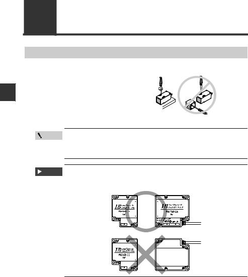
•Do not stare into the beam.
•Do not disassemble this product. Laser emission from this product is not automatically stopped when it is disassembled.
Model |
IB-01/IB-05/IB-10/IB-30 |
Wavelength |
660 nm |
Output |
170 μW |
Pulse width |
30 μs |
FDA (CDRH) Part 1040.10 * |
Class 1 Laser Product |
IEC60825-1 |
Class 1 Laser Product |
*The classification is implemented based on IEC60825-1 following the requirement of Laser Notice No.50 of FDA (CDRH).
Point
Laser emission stop input
When laser emission stop input is set as an external input, laser emission can be stopped by turning on the external input (2 ms or more). Laser emission stays stopped while the external input is on. The laser is emitted within 3 ms after the external input is turned off.
IB-E |
96099E |
1 |
Troubleshooting
Turn the power OFF immediately in the following cases. Continuing use in an abnormal state can cause damage.
 WARNING • When water or foreign matter enters the product body
• When the product has been dropped or the case damaged
• When smoke or abnormal odors are emitted from the product
Precautions for Use
|
|
|
|
• Use this product with the correct power voltage. Failure to do so |
|
|
|
|
could result in fire or electric shock. |
|
|
WARNING |
||
|
|
|
• Do not disassemble or modify this product. Failure to observe this |
|
|
|
|
|
|
|
|
|
|
could result in fire or electric shock. |
|
|
|
|
|
|
|
|
|
|
|
|
|
|
• Always turn off the power of the main unit and any device connected to |
|
|
|
|
the main unit before connecting or disconnecting a cable. |
|
|
CAUTION |
||
|
|
|
• Do not turn the power off while modifying device settings. Doing so |
|
|
|
|
|
|
|
|
|
|
could result in the lost of some or all setting data. |
|
|
|
|
|
|
|
|
|
|
|
|
|
|
Installation Environment |
|
|
|
|
To ensure correct and safe use of this product, do not install it in the |
|
|
|
|
following type of environment. Failure to observe this could result in |
|
|
|
|
faults. |
|
|
|
|
• Location subject to high levels of moisture or dust, or which is |
|
|
|
|
poorly ventilated |
|
|
|
|
• Location subject to high temperatures, such as where product is |
|
|
|
|
subject to direct sunlight |
|
|
|
|
• Location subject to corrosive or flammable gases |
|
|
|
|
• Location directly subject to vibration or impact |
|
|
|
|
• Location subject to water, oil or chemical spray |
|
|
|
|
• Location where static electric is easily generated |
|
|
|
|
Effect of Contaminants |
|
|
NOTICE |
|
• Contaminants such as dirt, dust, water or oil may prevent a correct |
|
|
|
|
measurement from being made. |
|
|
|
|
• Remove any contaminants from the transmitter and receiver |
|
|
|
|
sections with clean air. If heavily contaminated, wipe the sections off |
|
|
|
|
with a soft cloth soaked with alcohol. |
|
|
|
|
• Remove any contaminants from the measurement target with clean |
|
|
|
|
air, or wipe them off. |
|
|
|
|
• If contaminants are suspended in the measurement range, install a |
|
|
|
|
protective cover, or perform air purging, etc. |
|
|
|
|
Measures for Noise |
|
|
|
|
When installing this product near a source of noise such as a power |
|
|
|
|
cable or high voltage cable, it could malfunction or fail because of |
|
|
|
|
the noise. Provide measures for noise such as installing a noise |
|
|
|
|
filter, laying the cables in a separate conduit, or insulating the |
|
|
|
|
amplifier unit or sensor head. |
2 |
|
|
|
|
|
|
|
IB-E |
Warming Up
Wait at least 30 minutes after turning the power on before starting use. The circuit will be unstable immediately after the power is turned on so the display value may gradually fluctuate.
NOTICE
Power On Reset
Once the power is turned on, it will take approx. 2 seconds for the measurement to start. The judgment output will be output after the response time (average number of times x sampling rate) has elapsed.
Other Precautions
Power Supply
• The product could malfunction due to noise superimposed on the
WARNING power supply. Use a DC stabilized power supply with insulated transformer for the power supply.
•When using a commercially-available switching regulator, always ground the frame ground terminal.
Precautions on Regulations and Standards
CE Marking
Keyence corporation has confirmed that this product complies with the essential requirements of the applicable EC Directives, based on the following specifications. Be sure to consider the following specifications when using this product in the Member States of European Union.
|
EMC Directive |
EMI: EN60947-5-2, Class A |
||
|
• |
Applicable standards |
||
|
|
|
|
EMS: EN60947-5-2 |
|
These specifications do not guarantee that the end-product with this |
|||
|
product incorporated complies with the essential requirements of |
|||
|
the EMC Directives. The manufacturer of the end-product is solely |
|||
|
responsible for ensuring the compliance of the end-product. |
|||
|
Low-voltage Directive |
|
||
|
• |
Applicable standard: EN60825-1 |
||
NOTICE |
UL Certification |
|
|
|
|
This product is an UL/cUL Listed product. |
|||
|
• |
UL File No. |
E301717 |
|
|
• |
Category: |
NRKH, NRKH7 |
|
Be sure to consider the following specifications when using this product as a UL/cUL Listed Product.
•Use the power supply with Class 2 output defined in NFPA70 (NEC: National Electrical Code).
•The UL certificate for the IB series is for the sensor head and amplifier used in combination. The IB series sensor head must be used together with the IB series sensor amplifier unit exclusively.
•Power supply/ Control input/ Control output shall be connected to a single Class 2 source only.
•Use with the over current protection device which is rated 30V or more and not more than 1A.
•Use this product under pollution degree 2.
IB-E |
3 |

Table of Contents |
|
|
Introduction |
|
|
Safety Information for IB Series ................................................................ |
1 |
|
|
General Precautions ................................................................................ |
1 |
|
Safety Precautions on Laser Products..................................................... |
1 |
|
Troubleshooting ....................................................................................... |
2 |
|
Precautions for Use ................................................................................. |
2 |
|
Other Precautions .................................................................................... |
3 |
|
Precautions on Regulations and Standards............................................. |
3 |
Chapter 1 |
Before Use |
|
1-1 Checking the Package Contents ................................................... |
1-2 |
|
|
Sensor Amplifier Unit ............................................................................ |
1-2 |
|
Sensor Head ......................................................................................... |
1-3 |
|
List of Optional Parts............................................................................. |
1-4 |
1-2 Part Names and Functions............................................................ |
1-5 |
|
|
Sensor Amplifier Unit ............................................................................ |
1-5 |
|
Sensor Head Unit.................................................................................. |
1-8 |
Chapter 2 Installation and Connection |
|
|
2-1 Mounting and Wiring the Sensor Amplifier Unit............................. |
2-2 |
|
|
Mounting the Sensor Amplifier Unit ...................................................... |
2-2 |
|
Wiring the Sensor Amplifier Unit ........................................................... |
2-6 |
2-2 Connecting and Mounting the Sensor Head ................................. |
2-8 |
|
|
Mounting the Sensor Head ................................................................... |
2-8 |
|
Connecting the Sensor Head................................................................ |
2-9 |
Chapter 3 |
Basic Operations |
|
3-1 Operation when the Power Is Turned On for the First Time.......... |
3-2 |
|
3-2 Operations on the Main Screens................................................... |
3-3 |
|
|
R.V. (Internal Measurement Value) and P.V. (Judgment Value) .......... |
3-3 |
|
Main Display (Upper Level)................................................................... |
3-3 |
|
Sub Display (Lower Level) .................................................................... |
3-4 |
|
Setting Operations ................................................................................ |
3-6 |
3-3 Beam Axis Adjustment .................................................................. |
3-8 |
|
4 |
IB-E |

|
Beam Axis Adjustment Assistant Function ........................................... |
3-8 |
|
3-4 Reference Light Registration (Gain Adjustment) and Adjust Function... |
3-10 |
||
|
Reference Light Registration (Gain Adjustment) ................................ |
3-10 |
|
|
Adjust Function ................................................................................... |
3-11 |
|
|
Cancelling the Adjust Function (Reset)............................................... |
3-11 |
|
3-5 |
Initial Reset (Initialize)................................................................. |
3-12 |
|
3-6 Setting the Tolerance Setting Value ........................................... |
3-13 |
||
|
Manual Setting.................................................................................... |
3-14 |
|
|
Automatic Setting................................................................................ |
3-15 |
|
3-7 Zero Shift Function (Shifting the Internal Measurement Value (R.V.))... |
3-18 |
||
|
Setting the Shift Target Value............................................................. |
3-18 |
|
|
Performing the Zero Shift.................................................................... |
3-19 |
|
|
Canceling the Zero Shift (Reset)......................................................... |
3-19 |
|
3-8 Bank Function (Registering Multiple Tolerance Setting Values)...... |
3-20 |
||
|
Settings Registered with the Bank...................................................... |
3-20 |
|
|
How to Switch the Bank...................................................................... |
3-21 |
|
3-9 |
Key Lock Function ...................................................................... |
3-23 |
|
|
Starting the Key Lock.......................................................................... |
3-23 |
|
|
Canceling the Key Lock (Unlock)........................................................ |
3-23 |
|
|
|
||
Chapter 4 Setting Various Functions |
|
||
|
|
|
|
4-1 |
Setting Operations ........................................................................ |
4-2 |
|
4-2 Basic Settings and Advanced Settings ......................................... |
4-4 |
||
|
List of Setting Items .............................................................................. |
4-4 |
|
|
Setting Screen ...................................................................................... |
4-6 |
|
|
1. Measurement Mode .......................................................................... |
4-8 |
|
|
2. |
Received/Blocked Light Mode ........................................................ |
4-10 |
|
3. |
Averaging/High-Pass Filter ............................................................. |
4-11 |
|
4. |
Output Mode ................................................................................... |
4-13 |
|
5. |
Hold Function.................................................................................. |
4-14 |
|
6. |
Timing Input .................................................................................... |
4-23 |
|
7. |
Delay Timer..................................................................................... |
4-23 |
|
8. |
Hysteresis ....................................................................................... |
4-26 |
|
9. |
Analog Output Scaling .................................................................... |
4-27 |
|
10. External Input................................................................................ |
4-29 |
|
|
11. Bank Switching Method ................................................................ |
4-35 |
|
|
12. Save Zero-Shift State.................................................................... |
4-36 |
|
|
13. Save Adjust State ......................................................................... |
4-36 |
|
IB-E |
|
|
5 |

14. |
Adjust Level .................................................................................. |
4-37 |
15. |
Auto Adjust Function..................................................................... |
4-37 |
16. |
Check Output Function ................................................................. |
4-38 |
17. |
Error Output Mode ........................................................................ |
4-39 |
18. |
Display Digit.................................................................................. |
4-40 |
19. |
Power Save Function.................................................................... |
4-40 |
20. Judgment Indicator Color.............................................................. |
4-41 |
|
21. |
P.V. Value Display Color............................................................... |
4-41 |
4-3 Calibration Function .................................................................... |
4-42 |
Setting Method (Measured Correction)............................................... |
4-43 |
Setting Method (Logical Correction) ................................................... |
4-45 |
Chapter 5 Specifications
5-1 |
Specifications ................................................................................ |
5-2 |
|
Sensor Head ......................................................................................... |
5-2 |
|
Amplifier Unit......................................................................................... |
5-3 |
5-2 |
Circuit Diagram.............................................................................. |
5-4 |
|
Output Circuit ........................................................................................ |
5-4 |
|
Analog Output Circuit............................................................................ |
5-4 |
|
Input Circuit........................................................................................... |
5-5 |
5-3 |
Dimensions.................................................................................... |
5-6 |
|
Amplifier Unit......................................................................................... |
5-6 |
|
Sensor Head ......................................................................................... |
5-8 |
|
|
|
Chapter A Appendix |
|
|
|
|
|
Troubleshooting .................................................................................... |
A-2 |
|
|
Frequently Asked Questions................................................................. |
A-2 |
|
Error Displays and Corrective Actions .................................................. |
A-4 |
|
Non-Error Related Displays and Countermeasures.............................. |
A-7 |
Display Screen and Output ................................................................... |
A-9 |
|
Factory Setting (Default Value) List .................................................... |
A-10 |
|
Index ................................................................................................... |
A-11 |
|
6 |
IB-E |

|
|
|
|
|
Before Use |
1 |
|
This chapter describes the overview of the IB Series and the name |
|||
and function of each part. |
|||
|
|
|
|
1-1 |
Checking the Package Contents.......................... |
1-2 |
1-2 |
Part Names and Functions ................................... |
1-5 |
IB-E |
1-1 |
1
Use Before
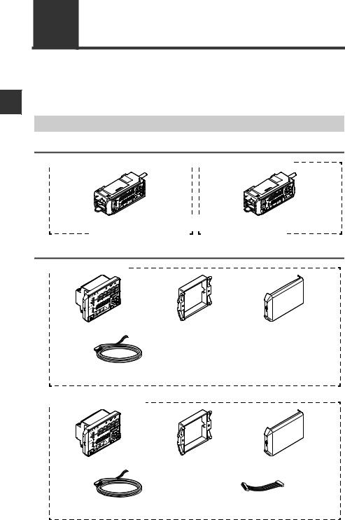
1-1 Checking the Package Contents
The following equipment and accessories are included in the package. Before using the unit, make sure that all items are included.
We have thoroughly inspected the package contents before shipment. However, in the event of defective or broken items, contact your nearest KEYENCE office.
Sensor Amplifier Unit
DIN rail mount type

 IB-1000 (main unit)


 IB-1050 (expansion unit)
Amplifier x 1 |
|
|
|
|
|
|
|
|
|
|
|
|
|
|
Amplifier x 1 |
|||||||||||||||||||||||||||||||||||
|
|
|||||||||||||||||||||||||||||||||||||||||||||||||
|
|
|||||||||||||||||||||||||||||||||||||||||||||||||
Instruction manual x 1 |
|
|
|
|
|
|
|
|
|
|
|
|
|
|
|
|
|
|
|
|
|
|
|
|
|
|||||||||||||||||||||||||
|
|
|
|
|
|
|
|
|
|
|
|
|
|
|
|
|
|
|
|
|
|
|
|
|
||||||||||||||||||||||||||
|
|
|
|
|
|
|
|
|
|
|
|
|
|
|
|
|
|
|
|
|
|
|
|
|
||||||||||||||||||||||||||
|
|
|
|
|
|
|
|
|
|
|
|
|
|
|
|
|
|
|
|
|
|
|
|
|
|
|
|
|
|
|
|
|
|
|
|
|
|
|
|
|
|
|
|
|
|
|
|
|
|
|
Panel mount type

 IB-1500 (main unit)
Amplifier x 1 |
Panel mounting |
Front protection |
|
bracket x 1 |
cover x 1 |
Power/Input-output cable (2 m) x 1 |
Instruction manual x 1 |
|
(Number of cable cores: 12) |
|
|

 IB-1550 (expansion unit)
Amplifier x 1 |
Panel mounting |
Front protection |
|
bracket x 1 |
cover x 1 |
Power/Input-output cable (2 m) x 1 |
Expansion cable |
|
(Number of cable cores: 8) |
|
(50 mm) x 1 |
1-2 |
IB-E |

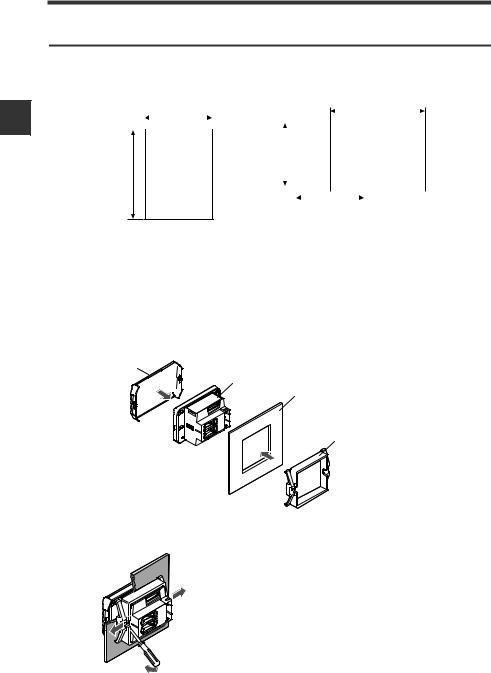
1-1 Checking the Package Contents
Sensor Head

 IB-01 (Measurement range φ1 to 2.5 mm)
L |
|
|
SA |
T |
|
RE |
|
|
|
|
R |
|
.oN |
LAI |
|
|
RES |
Transmitter x 1 Receiver x 1

 IB-05 (Measurement range 5 mm)
|
AL |
|
S |
|
|
RE |
|
T |
|
|
|
R
.oN  LAIRES
Mounting bracket x 2
Flat nut x 2
M3 x 20 mm screw x 4
Mounting bracket x 2
Flat nut x 2
Transmitter x 1 |
Receiver x 1 |

 IB-10 (Measurement range 10 mm)
|
AL |
|
|
|
|
ES |
T |
|
|
|
|
R |
|
|
|
|
|
|
|
R |
.oN |
LAI |
|
|
|
|
RES |
||
|
|
|
|
||
Transmitter x 1 Receiver x 1
M3 x 25 mm screw x 4
Mounting bracket x 2
Flat nut x 2
M3 x 25 mm screw x 4

 IB-30 (Measurement range 30 mm)
LASER
Mounting bracket x 2
M4 x 25 mm screw x 6
Transmitter x 1 |
Receiver x 1 |
1
Use Before
IB-E |
1-3 |
1
Use Before
1-1 Checking the Package Contents
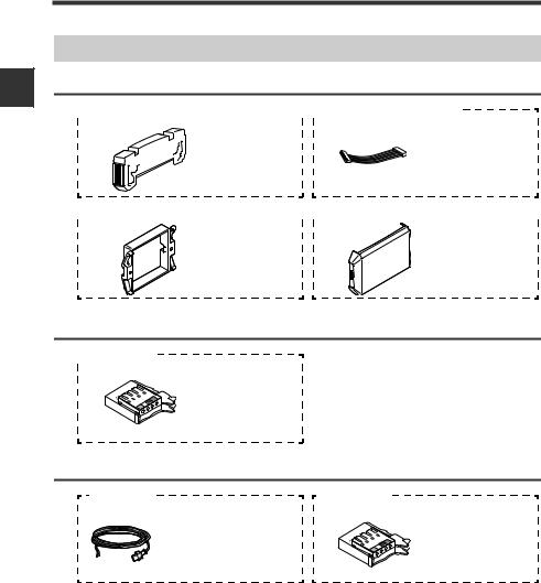
List of Optional Parts
For sensor amplifier unit

 OP-26751 (For IB-1000/IB-1050)


 OP-35361 (For IB-1550)
end unit |
Expansion cable |
x 2 |
(300 mm) x 1 |

 OP-4122 (For IB-1500/IB-1550)


 OP-87076 (For IB-1500/IB-1550)


Panel mounting |
Front protection |
bracket x 1 |
cover x 1 |
For sensor head

 OP-87060
Sensor head cable connector x 2
Extension cable
OP-87222 |
OP-87296 |
Extension cable (17m) × 1 |
Female connector x 1 |
Accessory |
|
• Female connector × 1 |
Dust cover x 1 |
*Male connector is connected |
|
1-4 |
IB-E |
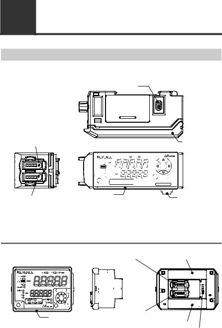
1-2 Part Names and Functions
Sensor Amplifier Unit
DIN rail mount type (IB-1000/IB-1050) |
1 |
|
|
||
|
|
|
|
|
|
Expansion unit connector*1 |
|
|
|
Use Before |
Sensor head connector (Transmitter) |
Amplifier control |
|
unit cover |
|
|
|
HOLD |
% |
CHECK |
|
LASER |
|
|
|
|
|
SELECT |
HI |
|
|
|
|
|
|
GO |
|
|
|
|
|
|
LO |
BANK0 |
|
|
|
|
|
Auto-ADJ |
1 |
|
|
|
SET |
MODE |
|
2 |
|
|
|
|
|
|
3 |
|
|
|
|
|
|
R.V. |
ANALOG |
|
|
ZERO SHIFT |
|
ZERO SHIFT |
HI |
LO |
SHIFT |
|
TIMING |
|
|
|
|
|
|
|
|
Amplifier control unit |
|
|
|
|
Expansion unit |
|
Sensor head connector (Receiver) |
|
|
|
|
|
|
|
|
|
|
|
connector*2 |
|
|
|
|
|
|
|
|
*1 When shipped from the factory, a protective cover is installed over the expansion slots.
*2 It is not installed on the main unit (IB-1000).
Panel mount type (IB-1500/IB-1550)
|
|
|
|
|
|
|
|
Sensor head connector (Transmitter) |
|
|
|
|
|
|
|
Expansion unit connector |
|
||||||||||||||||||||||||||||||||||||||||||||||||||||||||||
|
|
|
|
|
|
|
|
|
|
|
|
|
|
|
|
|
|
|
|
|
|
|
|
|
|
|
|
|
|
|
|
|
|
|
|
|
|
|
|
|
|
|
|
|
|
|
|
|
|
|
(Upper)*1 |
|
|||||||||||||||||||||||
|
|
|
|
|
|
|
|
|
|
|
|
|
|
|
|
|
|
|
|
|
|
|
|
|
|
|
|
|
|
|
|
|
|
|
|
|
|
|
|
|
|
|
|
|
|
|
|
|
|
|
|
|
|
|
|
|
|
|
|
|
|
|
|
|
|
|
|
|
|
|
|
|
|
|
|
Amplifier control unit |
Sensor head connector (Receiver) |
|
|
|
Expansion unit connector (Lower)*2 |
Power/Input-output cable connector
*1 It is not installed on the main unit (IB-1500).
*2 When shipped from the factory, a protective seal is attached.
IB-E |
1-5 |
|
1-2 Part Names and Functions |
|
|
|
|
|
|
||
|
Amplifier control unit |
|
|
|
|
|
|
|
|
1 |
DIN rail mount type (IB-1000/IB-1050) |
|
|
|
|||||
(1) |
|
(16) |
(15) |
(14) |
|
|
|
||
|
|
|
|
|
|
|
|
||
Before |
(2) |
|
|
|
|
|
|
|
|
(3) |
|
|
|
|
|
|
|
(13) |
|
|
|
|
|
|
|
|
|
||
|
|
|
|
|
|
|
|
|
|
Use |
(4) |
|
|
|
|
|
|
|
|
(5) |
|
|
|
|
|
|
|
|
|
|
(6) |
(7) |
(8) |
(9) (10) |
(11) |
(12) |
|||
|
Panel mount type (IB-1500/IB-1550) |
|
|
|
|||||
|
(1) |
|
(16) |
(15) |
(14) |
|
|
||
|
|
|
|
|
|
|
|
|
|
|
(2) |
|
|
|
|
|
|
|
|
|
(3) |
|
|
|
|
|
|
|
|
|
(4) |
|
|
|
|
|
|
|
|
|
(5) |
|
|
|
|
|
|
|
|
|
|
|
|
|
|
|
|
|
(13) |
|
(6) |
(7) |
(8) (9)(10) |
|
(11) |
(12) |
|
||
|
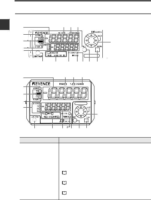
Item |
|
|
|
|
|
|
|
Description |
(1) |
Main display |
Displays the judgment value (P.V.) and various setting items. |
||
|
|
|
|
|
(2) |
Laser emission |
Turns on while the laser beam is emitted. Flashes when laser |
||
|
warning indicator |
beam is stopped. |
||
|
|
|
|
|
|
|
Indicates whether the judgment value (P.V.) in respect to the |
||
(3) |
Judgment indicator |
tolerance setting is HIGH (higher than the upper limit), GO |
||
(within tolerance range) or LOW (lower than the lower limit). |
||||
|
|
|||
|
|
|
"3-6 Setting the Tolerance Setting Value" (page 3-13) |
|
|
|
|
||
|
|
|
|
|
(4) |
Auto adjust indicator |
Turns on while the auto adjust function is operating. |
||
|
" 15. Auto Adjust Function" (page 4-37) |
|||
|
|
|
||
|
|
|
|
|
|
|
Indicates the bank in use. |
||
(5) |
Bank indicator |
|
"3-8 Bank Function (Registering Multiple Tolerance Setting |
|
|
||||
|
|
|
Values)" (page 3-20) |
|
1-6 |
IB-E |

|
|
|
|
1-2 Part Names and Functions |
|
|
|
|
|
|
|
|
|
|
|
|
|
|
|
Item |
|
Description |
|
|
|
|
Press this to set the internal measurement value (R.V.) to the |
||
(6) |
Zero shift button |
shift target value. |
|||
|
"3-7 Zero Shift Function (Shifting the Internal Measurement |
||||
|
|
|
|
||
|
|
|
|
Value (R.V.))" (page 3-18) |
|
|
|
|
|
|
|
(7) |
Sub display |
Turns on according to the type of value displayed on the sub |
|||
|
|
identification indicator |
display. |
||
|
|
|
|
|
|
(8) |
Sub display |
Displays the internal measurement value (R.V.), analog output |
|||
value and various settings (selections). |
|||||
|
|
|
|||
|
|
|
|
|
|
|
|
|
If the timing input (external input) is set to level, this indicator |
||
(9) |
Timing input indicator |
lights while the timing input is on. If the timing input is set to |
|||
edge, this indicator turns on for approx. 0.5 seconds when the |
|||||
|
|
|
|||
|
|
|
timing input is on. |
||
|
|
|
|
||
|
(10)Zero shift indicator |
Turns on for approx. 0.5 seconds when zero shift is executed. |
|||
|
|
|
|
|
|
|
(11) SET button |
When making various settings, press this button to |
|||
|
automatically set the setting value. |
||||
|
|
|
|||
|
|
|
|
|
|
|
(12)MODE button |
When making various settings, press this button to start or end |
|||
|
the setting or to move the item. |
||||
|
|
|
|||
|
|
|
|
|
|
|
(13)Arrow buttons |
Use this to select the setting item or to change the details |
|||
|
displayed on the sub display. |
||||
|
|
|
|||
|
|
|
|
|
|
|
(14)Check indicator |
Turns on when the check output is on. |
|||
|
|
" 16. Check Output Function" (page 4-38) |
|||
|
|
|
|
||
|
|
|
|
|
|
|
(15)Percentage indicator |
Turns on when the measurement mode is % mode. |
|||
|
|
" 1. Measurement Mode" (page 4-8) |
|||
|
|
|
|
||
|
|
|
|
|
|
|
(16)Hold indicator |
Turns on when the judgment value (P.V.) is held. |
|||
|
|
" 5. Hold Function" (page 4-14) |
|||
|
|
|
|
||
|
|
|
|
|
|
1
Use Before
IB-E |
1-7 |
1
Use Before
1-2 Part Names and Functions
Sensor Head Unit
IB-01/IB-05/IB-10/IB-30
Laser transmitter Laser receiver
|
|
|
R |
|
Transmitter |
T |
|
R |
Receiver |
|
LASER |
|
|
|
|
|
|
|
R |
|
LA |
T |
|
|
|
SER |
|
|
|
|
|
LASERT |
|
Receiver head |
|
|
|
|
connector |
Transmitter head connector
(1) Laser emission warning indicator
|
Item |
|
Description |
|
|
Always on when the power is supplied to the sensor head. |
|
|
|
Flashes while using the beam axis adjustment assistant |
|
(1) Laser emission warning |
function. The flashing cycle quickens as the received |
||
indicator |
amount increases and can be uses as a guide for adjusting |
||
|
|
the beam axis. |
|
|
|
|
" Beam Axis Adjustment Assistant Function" (page 3-8) |
|
|
|
|
|
|
|
|
|
|
|
|
Point
Use a transmitter and receiver with the same serial No. combination. The operation and accuracy cannot be guaranteed if units with different serial numbers are used in combination. The serial No. is attached to the top of the transmitter and receiver.
Receiver Transmitter
SERIAL No. |
No. |
12345678 12345678
1-8 |
IB-E |

Installation and Connection |
2 |
This chapter describes precautions when installing and connecting |
|
the IB Series. |
2-1 Mounting and Wiring the Sensor Amplifier Unit 2-2
2-2 Connecting and Mounting the Sensor Head....... |
2-8 |
IB-E |
2-1 |
2
Connection and Installation
2-1 Mounting and Wiring the Sensor Amplifier Unit
Mounting the Sensor Amplifier Unit
DIN rail mount type, main unit (IB-1000)
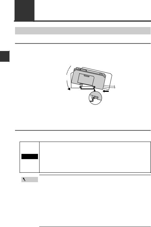
1 |
Align the claw at the bottom of the main body with the DIN rail. While |
pushing the main body in the direction of the arrow (1), tilt the amplifier in |
the direction of the arrow (2).
(3)
|
(2) |
(1) |
|
|
|
2 |
To remove the amplifier, raise the main body in the direction of the arrow |
|
(3) while pushing it in the direction of the arrow (1). |
||
DIN rail mount type, expansion unit (IB-1050)
Expansion units must be connected to the main unit before they can be used. Up to 3 expansion units can be connected to one main unit.
•When connecting multiple amplifiers (expansion units), first check to make sure that the power is turned off to all of the main and
expansion units. Installing an expansion unit with power on may  CAUTION damage this device.
• Push the amplifiers (expansion units) as far as possible into the main unit. If they are connected at an angle or not inserted securely, this device could get damaged.
Point
• When connecting the expansion units, make sure to initialize the expansion units and set the output polarity.
(1)When turning on the amplifier for the first time after connecting the sensor head please reference
 "3-1 Operation when the Power is Turned On for the First Time" (page 3-2)
(2) When initializing the unit please reference
 "3-5 Initial Reset (Initialize)" (page 3-12)
•Expansion units with different settings for output polarity (such as an NPN output expansion unit to a PNP output main unit) cannot be connected together.
•Expansion units using DIN rail mount cannot be connected to a panel mount style main unit.
2-2 |
IB-E |
|
2-1 Mounting and Wiring the Sensor Amplifier Unit |
1 |
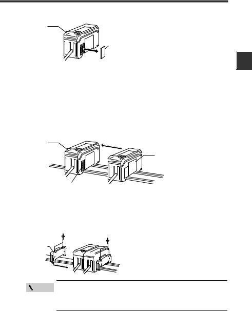
Remove the expansion protective cover from the IB-1000 (main unit). |
Main unit |
|
|
Connector cover |
2 |
Install the amplifiers (expansion units) onto the DIN rail. |
|
Do the same as instructed under “DIN rail mount type, main unit.” |
3 |
Push the expansion unit into the main unit connector until a clicking |
sound can be heard. |
The expansion unit installed next to the main unit is referred to as expansion unit 1. Subsequent expansion units are referred to as expansion unit 2, expansion unit 3, and so on.
|
Main unit |
|
Expansion |
|
unit |
|
Connecter |
4 |
Install the end units (OP-26751: 2 units per set) (sold separately) on both |
sides of the amplifiers (main or expansion units). Secure the end units in |
place with screws on top (2 on each end unit).
The end units are mounted in the same way as the amplifiers.
End unit


 End unit
Point
Mount the amplifiers securely using the end units (OP-26751: 2 units per set) (sold separately) or a commercially available DIN rail mounting tool to prevent the amplifiers from slipping and coming off from the DIN rail due to machine vibration.
2
Connection and Installation
IB-E |
2-3 |
2
Connection and Installation
2-1 Mounting and Wiring the Sensor Amplifier Unit
Panel mount type, main unit (IB-1500)
1 |
Make a hole on the panel as shown in the diagrams below. |
|||||||||||||||||
When stacking the units vertically |
When stacking the units horizontally |
|||||||||||||||||
|
|
|
|
|
45 mm + 0.6 |
|
|
|
|
|
|
Minimum 85 mm |
||||||
|
- 0 |
|
|
|
|
|
|
|
|
|
|
|
|
|
||||
|
|
|
|
|
|
|
|
|
|
|
|
|
|
|||||
|
|
|
|
|
|
|
|
|
|
|
|
|
|
|
|
|
|
|
|
|
|
|
|
|
|
|
|
|
|
|
|
|
|
|
|
|
|
|
|
|
|
|
|
|
|
45 mm |
|
|
|
|
|
|
|
|||
|
|
|
|
|
|
|
|
+ 0.6 |
|
|
|
|
|
|
|
|
|
|
|
X mm |
- 0 |
|
|
|
|
|
|
|
|
|
|
||||||
|
|
|
|
|
|
|
|
|
|
|
|
|||||||
|
|
|
|
|
|
|
|
|
|
|
|
|
|
|
|
|
|
|
|
|
|
|
|
|
|
|
|
|
|
|
|
|
|
|
|
|
|
|
|
|
|
|
|
|
|
|
|
|
|
|
|
|
|
|
|
|
|
|
|
|
|
|
|
|
|
|
|
|
|
|
|
|
|
|
|
|
|
|
|
|
|
|
|
|
|
|
|
|
|
|
|
|
|
|
45 mm + 0.6 - 0
•Panel thicknes 1 to 6 mm
•X = 48 x (Number of amplifiers) - 3
2 Insert the back side of amplifier to the hole of the panel.
3 |
Arrange the panel mounting tool in the direction below, mount to the |
amplifier from the back and attach the front protection cover to the |
|
|
amplifier. |
|
Front protection |
|
cover |
|
Amplifier |
|
Panel |
|
Panel mounting |
|
bracket |
To remove the panel mounting tool, widen the claws at both ends of the panel mounting tool using a screwdriver, as illustrated below.
2-4 |
IB-E |
2-1 Mounting and Wiring the Sensor Amplifier Unit
Panel mount type, expansion unit (IB-1550)
Several expansion units can be used in connection with the main unit. Up to 3 expansion units can be connected to one main unit.
|
|
|
|
• When connecting the expansion cable, make sure to turn off the |
|
|
|
|
power beforehand. Inserting or removing the cable with the power |
|
|
|
|
turned on may cause damage to the units. |
|
CAUTION |
|||
|
|
|
• Push the expansion cable connector securely all the way. If it is |
|
|
|
|
|
|
|
|
|
|
connected at an angle or not inserted securely, the units could get |
|
|
|
|
damaged. |
|
|
|
|
|
|
|
|
|
|
|
|
|
|
• When connecting the expansion units, make sure to initialize the |
|
Point |
|
||
|
|
|
connected expansion units and set the output polarity. |
|
|
|
|
|
(1) When turning on the amplifier for the first time after connecting the sensor head
 "3-1 Operation when the Power is Turned On for the First Time" (page 3-2)
(2) When initializing the unit
 "3-5 Initial Reset (Initialize)" (page 3-12)
•Expansion units with different settings for output polarity (such as an NPN output expansion unit to a PNP output main unit) cannot be connected together.
•Expansion units using panel mount cannot be connected to a DIN rail mounted main unit.
1Make the appropriate number of holes in the panel according to the number of amplifiers required (expansion units).
For the panel cutting measurement, refer to “Panel mount type, main unit”.
2Install the amplifiers (expansion units) on the panel.
For the amplifier mounting method, refer to “Panel mount type, main unit”.
3Connect the amplifiers (main and expansion units) using the expansion cable (50 mm) supplied with the expansion unit.
The expansion unit installed next to the main unit is referred to as expansion unit 1. Subsequent expansion units are referred to as expansion unit 2, expansion unit 3, and so on.
Main unit
|
|
Expansion cable |
|
|
Expansion unit |
|
Reference |
When arranging the amplifiers side by side, the 300 mm expansion cable |
|
(OP-35361) is required. |
|
|
|
|
IB-E |
|
2-5 |
2
Connection and Installation
2
Connection and Installation
2-1 Mounting and Wiring the Sensor Amplifier Unit
Wiring the Sensor Amplifier Unit
Connecting the power/input-output cable (for panel mount type only)
Connect the power/input-output cable to the panel mount type main unit and the input/ output cable to the expansion unit.
To attach |
To remove |
Power/Input-output cable
Point
• The number of core wires for the power/input-output cable for the main unit is 12, and the number of core wires for the input-output cable for the expansion units is 8.
•Power for the expansion units is supplied from the main unit.
•When not using the I/Os of expansion unit, cut the cable near the connector.
2-6 |
IB-E |
2-1 Mounting and Wiring the Sensor Amplifier Unit
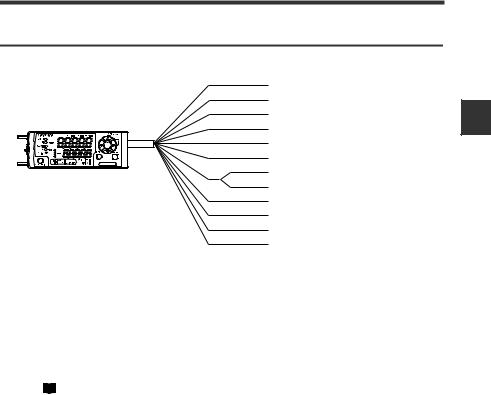
Power/Input-output cable
 "Output Circuit" (page 5-4)
Brown *1
Blue *1
Black
White
Gray
Green
Light blue*1 Orange *2
Shield *2
Pink *3
Yellow *3
Pink/Purple *3
Purple *3
10 to 30 VDC
0 V
HIGH judgment output
LOW judgment output
GO judgment output
Check output
Analog output +
Analog output GND
External input 1 (Zero shift input) External input 2 (Reset input) External input 3 (Timing input) External input 4 (Not used)
*1 IB-1050/IB-1550 (expansion units) do not have brown, blue or light blue wires. Power is supplied to the expansion units through IB-1000/IB-1500 (main unit).
*2 The analog output can be set to any of the following options either “when the power is turned on for the first time” or “when performing the initial reset”.
•Not used (OFF)
•0 to 5 V
•-5 to 5 V
•1 to 5 V
•4 to 20 mA
 "3-1 Operation when the Power is Turned On for the First Time" (page 3-2)
 "3-5 Initial Reset (Initialize)" (page 3-12)
*3 The external input can be selected among the following in addition to the above.
•Bank A input
•Bank B input
•Laser emission stop input
•Not used (OFF)
Adjust input can be selected only for the external input 4.
 "10. External Input" (page 4-29)
2
Connection and Installation
IB-E |
2-7 |
2
Connection and Installation
2-2 Connecting and Mounting the Sensor Head
Mounting the Sensor Head
Mounting
Mount the sensor head with the enclosed screws (IB-01/IB-05/IB-10: M3, IB-30: M4).
Tightening torque: 0.3 N·m or less (Tightening torque for IB-01: 0.1 N·m or less)
Point
• Always use mounting holes facing the same direction for the sensor head transmitter and receiver. (Excluding IB-01)
•Do not tighten the screws with a torque exceeding 0.3 N·m. The sensor head could deform, thus preventing beam axis alignment.
Important
When mounting the sensor, confirm that the transmitter and receiver faces on which the nameplate label is attached are facing the same direction. (Only for IB-30)
2-8 |
IB-E |
2-2 Connecting and Mounting the Sensor Head
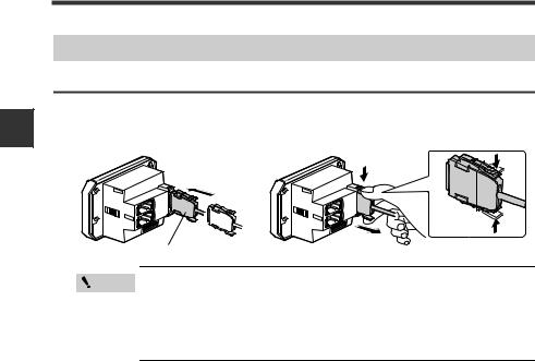
Connecting the Sensor Head
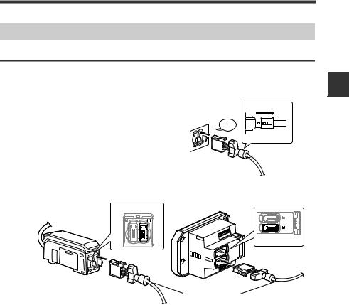
Connecting the sensor head and sensor amplifier unit
1 |
Attach the receiver’s sensor head connection cable to the amplifier’s [R] |
|
connector. |
|
|
|
Remove the lock cover of the connector and |
Lock cover |
|
insert it into the connectors of amplifier until a |
|
|
|
|
|
clicking sound can be heard. |
Click |
|
|
|
|
|
Unlocked |
DIN rail mount type |
Panel mount type |
(IB-1000/IB-1050) |
(IB-1500/IB-1550) |
Right side is [R] side
Bottom is [R] side
Blue ring
2
Connection and Installation
IB-E |
2-9 |
2
Connection and Installation
2-2 Connecting and Mounting the Sensor Head
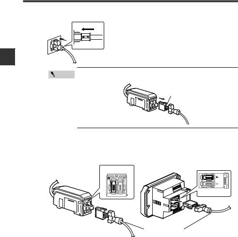
2 Attach the lock cover to the connector to secure the cable.
Lock cover
Locked
Point |
When removing the sensor head connection cable, push |
|
the lock lever and pull it out. |
||
|
||
|
Lock lever |
3 |
Attach the transmitter’s sensor head connection cable to the amplifier’s |
|
[T] connector. |
|
|
|
DIN rail mount type |
Panel mount type |
|
(IB-1000/IB-1050) |
(IB-1500/IB-1550) |
Left is [T] side
Top is [T] side
Red ring
The connection procedures are the same as the receiver side.
2-10 |
IB-E |
2-2 Connecting and Mounting the Sensor Head
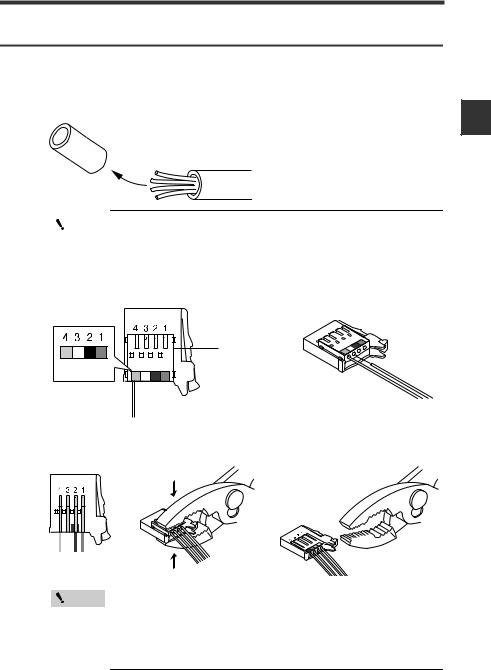
Attaching the sensor head cable connector (OP-87060)
Cut the sensor head cable to the required length and attach the new connector to use the sensor. The connection method is the same for the transmitter and receiver.
1 |
Cut the cable to the required length and strip approx. 15 mm of insulation |
from the end. |
|
|
Point |
|
Do not strip the core wire insulation. |
2 |
|
|
||
Insert each color coded cable into the same colored marked points on the |
||||
connector. |
|
|
||
Each cable is secured temporarily when it is inserted completely.
Insert further
than here.
Blue Black
White Brown
2
Connection and Installation
3 |
Confirm that all the cables are inserted properly into the connector and |
|||||||||||||
crimp them using pliers or a similar tool. |
||||||||||||||
|
|
|
|
|
|
|
|
|
|
|
|
|
|
|
|
|
|
|
|
|
|
|
|
|
|
|
|
|
|
|
|
|
|
|
|
|
|
|
|
|
|
|
|
|
|
|
|
|
|
|
|
|
|
|
|
|
|
|
|
|
|
|
|
|
|
|
|
|
|
|
|
|
|
|
|
|
|
|
|
|
|
|
|
|
|
|
|
|
|
|
|
|
|
|
|
|
|
|
|
|
|
|
|
|
|
|
|
|
|
|
|
|
|
|
|
|
|
|
|
|
|
|
|
|
|
|
|
|
|
|
|
|
|
|
Point
Once the connector has been installed, make sure to connect it to the amplifier and confirm that the sensor operates normally.
If the sensor head does not function properly, crimp the connector again using pliers or a similar tool.
Once the connector is crimped, it cannot be reused.
IB-E |
2-11 |

2-2 Connecting and Mounting the Sensor Head
MEMO
2
Connection and Installation
2-12 |
IB-E |

|
|
|
|
|
Basic Operations |
3 |
|
This chapter describes basic operations and settings for the IB |
|||
Series. |
|||
|
|
|
|
3-1 Operation when the Power is Turned On for the
|
First Time ............................................................... |
3-2 |
3-2 Operations on the Main Screens ......................... |
3-3 |
|
3-3 |
Beam Axis Adjustment ......................................... |
3-8 |
3-4 Reference Light Registration (Gain Adjustment) and |
||
|
Adjust Function ................................................... |
3-10 |
3-5 |
Initial Reset (Initialize)......................................... |
3-12 |
3-6 Setting the Tolerance Setting Value .................. |
3-13 |
|
3-7 Zero Shift Function (Shifting the Internal |
|
|
|
Measurement Value (R.V.)) ................................. |
3-18 |
3-8 |
Bank Function (Registering Multiple Tolerance |
|
|
Setting Values)..................................................... |
3-20 |
3-9 |
Key Lock Function .............................................. |
3-23 |
IB-E |
3-1 |
3
Operations Basic
3-1 Operation when the Power is Turned On for the First Time
When the amplifier is turned on for the first time after the sensor head is connected, the initial setting display appears. Make the initial setting according to the following procedure as this is necessary for both the main unit and the expansion units when units are added.
Point
Once the initial setting is completed, the initial setting display will not appear when the power is turned on the second time or the after. To change the initial setting, perform the initial reset.
 "3-5 Initial Reset (Initialize)" (page 3-12)
Power ON
HOLD  CALC
CALC CHECK
CHECK
LASER |
|
HI |
|
GO |
|
LO BANK
ALIGNMENT 01
2
3
Output  polarity
[MODE] button
HOLD  CALC
CALC CHECK
CHECK
LASER |
|
HI |
|
GO |
|
LO BANK
ALIGNMENT 01
2
3
Analog output
[MODE] button
|
|
HOLD |
CALC CHECK |
LASER |
|
|
|
HI |
|
|
|
GO |
|
|
|
LO |
BANK0 |
|
|
ALIGNMENT |
1 |
|
|
|
2 |
|
|
|
3 |
|
|
|
R.V. |
ANALOG |
ZERO SHIFT |
|
HI |
LO SHIFT |
TIMING |
1 |
Select the judgment output and check output polarity |
||
with the / button, and press the [MODE] button. |
|||
|
Setting value |
Description |
|
|
npn |
NPN output |
|
|
pnp |
PNP output |
|
2 |
Press the / button to select the analog output |
||
method and press the [MODE] button. |
|||
|
|
|
|
|
Setting value |
Description |
|
|
off |
Not output |
|
|
0-5u |
Analog output after the judgment value is converted to |
|
|
the range from 0 to 5 V. |
||
|
|
|
|
|
-5-5u |
Analog output after the judgment value is converted to |
|
|
±5 V. |
||
|
|
|
|
|
1-5u |
Analog output after the judgment value is converted to |
|
|
the range from 1 to 5 V. |
||
|
|
|
|
|
aMpr |
Analog output after the judgment value is converted to |
|
|
the range from 4 to 20 mA. |
||
|
|
|
|
3 |
|
"9. Analog Output Scaling" (page 4-27) |
|
|
|||
After the setting is complete, [end] blinks several |
|||
times on the sub display and changes to the main |
|||
screen.
4 |
Carry out "3-3 Beam Axis Adjustment" (page 3-8) and "3-4 Reference |
Light Registration (Gain Adjustment) and Adjust Function" (page 3-10). |
Make other settings as necessary.
3-2 |
IB-E |
Loading...