


 Loading...
96M10260
AutoID Data Controller
DV-90
User’s Manual
Read this manual before using the system in order to achieve maximum performance.
Keep this manual in a safe place for future reference.

Introduction
This manual describes instructions on basic usage of the DV-90, its operation procedures, warnings and precautions.
Be sure to read this section thoroughly before use. Keep this manual in a safe place for future reference.
Symbols and Conventions
The following symbols and conventions alert you to important messages. Be sure to read these messages carefully.
|
|
|
WARNING |
Failure to follow instructions may lead to physical injury (electric shock, burn, etc). |
||||||
|
|
|
|
|
||||||
|
|
|
CAUTION |
|
Indicates the cautions and restrictions that are necessary for proper operation. |
|||||
|
|
|
|
|
|
|
|
|
|
|
|
|
|
|
|
|
|
|
|
|
Failure to follow instructions may lead to product damage. |
|
|
Important |
|
|
|
|||||
|
|
|
|
|
|
|
|
|
|
|
|
|
|
|
|
|
|
|
|
|
Indicates an important operating procedure that could be easily mistaken. |
|
|
|
Note |
|
|
|
|
|
||
|
|
Reference |
|
|
|
|
Provides advanced and useful information for operation. |
|||
|
|
|
|
|
|
|
|
|
|
Indicates the reference page of this manual, or the one in another manual. |
|
|
|
|
|
|
|
|
|
|
|
General Cautions
•Before starting work or before starting the system, confirm that all the functions of the system are working properly.
•We recommend that you take substantial safety measures to avoid any damage in the event of a problem occurring.
•Do not modify the DV-90, or use it in any way other than described in the specification.
•When the DV-90 is used in combination with other instruments, functions and performance may be degraded, depending on the operating conditions and surrounding environment.
•Do not use the DV-90 for the purpose of protecting the human body.
•Do not change the temperature drastically around the DV-90 and other devices, including the accessories. Otherwise, condensation may be generated.
•Turn off the power of the DV-90 for safety when not using the DV-90 for a long period of time.
Safety Precautions
Tips on Correct Use
zHandling
•Do not attempt to open or modify the DV-90. Doing so may cause fire and electric shock. zHandling abnormalities
|
|
|
|
Turn off the power immediately in the following cases. Using the unit in an abnormal con- |
|
WARNING |
|
||
|
|
dition could cause fire, electric shock, or accident. |
||
|
|
|
|
• Contact the nearest KEYENCE office for repair. |
|
|
|
|
|
|
|
|
|
• If liquid including water, chemicals or debris enters the unit. |
|
|
|
|
• If a metal contacts the connector. |
|
|
|
|
• If the unit is dropped or the case is damaged. |
|
|
|
|
• If abnormal smoke or odor is present. |
|
|
|
|
zHandling |
|
|
|
|
• The DV-90 uses 24V DC for the supplied power voltage. Use of any other power supply |
|
|
|
|
than this may damage the DV-90. |
|
|
|
|
• The 5V DC power voltage supplied from the pin 9 of the 9-pin D-sub power supply is the |
|
|
|
|
supplied power dedicated for the Keyence code reader. Do not use it for any other |
|
|
|
|
devices than for the Keyence code reader. Otherwise, the connected device may be |
|
|
|
|
damaged. |
|
|
|
|
The maximum current that can be supplied to the connected code reader is 1100 mA. |
|
|
|
|
Ensure that the sum of the current consumption of the code reader connected to the DV- |
|
|
|
|
90 stays under this value. |
|
|
|
|
However, when the ambient temperature exceeds 40 °C, the maximum power current that |
|
|
|
|
can be supplied is 850 mA. |
|
|
|
|
• Be sure to turn off the power of the DV-90 and of the connected devices when you plug/ |
|
|
|
|
unplug the cable. Otherwise, the DV-90 and the connected devices may be damaged. |
|
|
|
|
• Isolate the cable from devices that generate high frequency, power supply lines or power |
|
CAUTION |
|
|
|
|
|
lines. Otherwise, noise could cause malfunction or accident. |
||
|
|
|
|
|
|
|
|
|
• Do not damage, pull or heat the cable. |
|
|
|
|
zOperating environment/condition |
|
|
|
|
To use the DV-90 correctly and safely, avoid installing it in the following locations. Failure to |
|
|
|
|
do so may cause fire, electric shock and malfunction. |
|
|
|
|
• Location that is humid, dusty or poorly ventilated |
|
|
|
|
• Location that is unstable such as an unsettled table or tilted surface |
|
|
|
|
• Location with a high temperature such as a place exposed to direct sunlight |
|
|
|
|
• Location where there are flammable or corrosive gases |
|
|
|
|
• Location where the unit may be directly subjected to vibration or impact |
|
|
|
|
• Location where water, oil or chemicals may splash onto the DV-90 |
|
|
|
|
• Location where static electricity is easily generated |
|
|
|
|
zOperating environment/condition |
|
|
|
|
• Disconnect the power supply unit at the time of maintenance. |
|
|
|
|
• Do not wipe the DV-90 with benzene, thinner or alcohol. Doing so could change the color |
|
|
|
|
or shape of the unit. If the unit has any dirt on it, wipe it off with a cloth moistened with a |
|
|
|
|
mild detergent, then rub with a dry cloth. |
E DV-90-IM |
96M10260 |
1 |
|

CE Marking and UL Conformity
CE Marking
It is confirmed that the DV-90 Series satisfies the requirements of the EU Directive, and conforms to it when the following conditions are fulfilled.
Therefore, users must fulfill the following conditions when the DV-90 Series is going to be used in the EU countries.
●Precautions for EMC Directive (89/336/EEC)
• |
Applicable standard |
|
|
(EMI) EN55011 Class A |
|
• |
Applicable standard |
|
|
(EMS) EN61000-6-2 |
|
• |
Attach the following ferrite cores |
|
|
to the connected cables. |
|
|
I/O terminal: |
ZCAT3035-1330 |
|
USB: |
ZCAT2035-0930 |
|
PORT1 (code reader): |
|
|
|
ZCAT2035-0930 |
|
PORT2: |
ZCAT1325-0530 |
|
* Attach the ferrite cores on |
|
|
both ends of the cable con- |
|
|
nected to PORT2. |
|
* Above ferrite cores are manufactured by TDK Corporation.
•Keep the cables on the I/O terminals shorter than 30 m.
UL Approval
The DV-90 Series comply with to the following UL standard and has acquired UL Certificate.
• Applicable standard |
UL508 Industrial Control Equipment |
|
CAN/CSA C22.2 No.14 Industrial Control Equipment |
• UL File No. |
E207185 |
• UL category |
NRAQ/NRAQ7 |
15JN Industrial Control Equipment
<Precautions>
•For the power supply of the DV-90, be sure to use a UL Listing certified power supply with the Class 2 output as specified in the NFPA70 (NEC: National Electrical Code) of the United States.
•When wiring to the power terminal block of the DV-90 Series, be sure to use wires with range of
AWG#14 – #20, copper wire, stranded wire, and temperature rating of 60°C or more. The tightening torque for wiring is 5 kg.cm (0.5 Nm).
•For the wires to connect to the I/O terminal block of the DV-90 Series, be sure to use wires with range of AWG#16-#26, copper wire, stranded wire, and temperature rating of 60°C or more. The tightening torque for wiring is 1.7Lb • in (0.2 Nm).
•Install the DV-90 Series by following the installation and wiring methods specified in this manual. Be sure to use the DV-90 based on the product specifications outlined in this manual.
•DV-90 is for use on a flat surface of Type 1 Enclosure.
2 |
E DV-90-IM |
|

Software Licensing Agreements
Read the following licensing agreement carefully before using this software.
By using the software, you signify that you agree with the statements herein and the contract is accepted.
Licensing
1.Right of use
KEYENCE grants you the nonexclusive right to use this software in accordance with terms of this agreement.
2.Copyright
The copyright on the software and supplied documentation belongs to KEYENCE Corporation, and you hold only the license for its use.
3.Prohibited matters
You may not copy this software and sell or distribute to a third party. However, you may copy this software for the purpose of keeping backup copy for your personal use.
4.Indemnification
In no event shall KEYENCE be liable for any damages you and the third parties suffer from, arising from the usage of this software.
5.Cancellation of contract
KEYENCE may terminate this agreement if you fail to comply with the terms of this agreement. In such event, you must return the software and all copies to KEYENCE or destroy.
E DV-90-IM |
3 |
|

Content
Safety Precautions ....................................................................................................................................... |
1 |
CE Marking and UL Conformity ................................................................................................................... |
2 |
Software Licensing Agreements .................................................................................................................. |
3 |
Content ........................................................................................................................................................ |
4 |
Manual Structure .......................................................................................................................................... |
9 |
Chapter 1 Getting Started
1-1 |
Checking the Package Contents.................................................................................................. |
1-2 |
1-2 |
Overview of DV-90 Functions ....................................................................................................... |
1-3 |
|
Automated Product Selection at an Assembly Workstation ....................................................................... |
1-3 |
|
Preventing Mixing with Other Products at a Packaging Machine .............................................................. |
1-4 |
|
Preventing Misplacement of Raw Material ................................................................................................ |
1- 5 |
|
Preventing Mispackaging in a Manual Packaging Process......................................................................... |
1- 6 |
|
Verifying the Assembly Instruction by Comparing with the Customer Order Sheet (Kanban) ................. |
1- 7 |
|
Checking the Print Quality of the Expiration Date or Manufactured Date................................................. |
1- 8 |
|
Checking the Barcode Print Quality at the Printing Process ...................................................................... |
1- 8 |
1-3 |
DV-90 Layout ............................................................................................................................... |
1-9 |
1-4 |
System Configuration and Connectable Devices...................................................................... |
1-11 |
Chapter 2 Initial Setup of the Code Reader
2-1 |
Code Reader Setup Basics ......................................................................................................... |
2-2 |
|
How to Detect the Communication Setting Automatically ........................................................................ |
2-5 |
2-2 |
Setting Procedure of the BL Series and the SR Series................................................................ |
2-6 |
|
Setting Procedure Using the SetUp Software ............................................................................................. |
2-6 |
|
Setting Procedure Using "Quick Setup Code"(DV-90 SetUp Software).................................................... |
2-7 |
2-3 |
Read Test Procedure of the BL Series and the SR Series .......................................................... |
2-8 |
|
Read Test Using the TRG Key ...................................................................................................................... |
2-8 |
|
Read Rate Test Using “Test Mode 1” ......................................................................................................... |
2-8 |
|
Checking the Type of the Read Barcode .................................................................................................. |
2-10 |
Chapter 3 Connections and Mounting
3-1 |
I/O Terminal Connection.............................................................................................................. |
3-2 |
|
I/O Terminal Pin Assignment ..................................................................................................................... |
3-2 |
|
Wiring the Input Terminals......................................................................................................................... |
3-4 |
|
Wiring the Output Terminals (NPN Open Collector Type)........................................................................ |
3-5 |
|
Wiring the Output Terminals (PNP Open Collector Type) ........................................................................ |
3-6 |
3-2 |
RS-232C Interface Connection.................................................................................................... |
3-7 |
|
Pin Assignment of the RS-232C Interface .................................................................................................. |
3-7 |
|
Connecting the Code Reader....................................................................................................................... |
3-8 |
|
Connecting a PC or PLC........................................................................................................................... |
3-10 |
3-3 USB Interface Connection/Driver Installation ............................................................................ |
3-13 |
|
|
Notes on Installing the Driver Software ................................................................................................... |
3-13 |
|
Notes on Connecting the DV-90 ............................................................................................................... |
3-13 |
|
Installing the USB Driver Software .......................................................................................................... |
3-13 |
|
Uninstalling the USB Driver Software ..................................................................................................... |
3-23 |
3-4 |
Wiring the Power Supply Terminals........................................................................................... |
3-24 |
3-5 |
Mounting the DV-90................................................................................................................... |
3-25 |
4 |
E DV-90-IM |
|

Chapter 4 Basic Functions
4-1 |
Verification Function .................................................................................................................... |
4-2 |
|
Notes on Registering Master Data .............................................................................................................. |
4-3 |
4-2 |
Normal Verification ...................................................................................................................... |
4-4 |
|
Normal Verification Function..................................................................................................................... |
4-4 |
|
Setting the Normal Verification Function................................................................................................... |
4-4 |
|
Presetting the Master Data (Preset Mode) .................................................................................................. |
4-5 |
|
Presetting from the Desired Record Number .............................................................................................. |
4-7 |
|
Deleting the Master Data ............................................................................................................................ |
4-7 |
|
Working with the Normal Verification Function (Verification Mode) ...................................................... |
4-8 |
|
Confirming the Master Data ....................................................................................................................... |
4-9 |
|
Counter Function......................................................................................................................................... |
4-9 |
|
Timing Chart for Parallel Output .............................................................................................................. |
4-11 |
|
Interlock Function ..................................................................................................................................... |
4-11 |
4-3 |
Active Verification ...................................................................................................................... |
4-13 |
|
Active Verification Function .................................................................................................................... |
4-13 |
|
Setting the Active Verification Function .................................................................................................. |
4-13 |
|
Presetting the Master Data (Preset Mode) ............................................................................................... |
4-14 |
|
Selecting the Active Record...................................................................................................................... |
4-14 |
|
Working with the Active Verification Function (Verification Mode) ...................................................... |
4-16 |
4-4 |
Step Verification Function.......................................................................................................... |
4-17 |
|
Step Verification Function ........................................................................................................................ |
4-17 |
|
Setting the Step Verification Function...................................................................................................... |
4-17 |
|
Working with the Step Verification Function........................................................................................... |
4-18 |
|
Timing Chart for Parallel Output .............................................................................................................. |
4-20 |
4-5 |
3-Point-A Verification Function .................................................................................................. |
4-21 |
|
3-Point-A Verification Function ............................................................................................................... |
4-21 |
|
Setting the 3-Point-A Verification Function ............................................................................................. |
4-21 |
|
Presetting the Master Data (Preset Mode) ................................................................................................ |
4-22 |
|
Working with the 3-Point-A Verification Function (Verification Mode)................................................. |
4-24 |
|
Timing Chart for Parallel Output .............................................................................................................. |
4-27 |
4-6 |
3-Point-B Verification Function .................................................................................................. |
4-28 |
|
3-Point-B Verification Function ............................................................................................................... |
4-28 |
|
Setting the 3-Point-B Verification Function ............................................................................................. |
4-28 |
|
Presetting the Master Data (Preset Mode) ................................................................................................ |
4-29 |
|
Working with the 3-Point-B Verification Function (Verification Mode)................................................. |
4-29 |
|
Timing Chart for Parallel Output .............................................................................................................. |
4-33 |
4-7 |
2-Point Verification Function ...................................................................................................... |
4-34 |
|
2-point Verification Function.................................................................................................................... |
4-34 |
|
Selecting the 2-point Verification Function.............................................................................................. |
4-34 |
|
Presetting the Master Data (Preset Mode) ................................................................................................ |
4-35 |
|
Working with the 2-point Verification Function (Verification Mode) ..................................................... |
4-36 |
|
Timing Chart of Parallel Output ............................................................................................................... |
4-38 |
Chapter 5 Extended Functions
5-1 |
Reference Data Function............................................................................................................. |
5-2 |
|
Reference Data Function............................................................................................................................. |
5-2 |
|
Using the Reference Data Function ............................................................................................................ |
5-3 |
5-2 |
Input Digit Limitation Function ..................................................................................................... |
5-4 |
E DV-90-IM |
5 |
|

Input Limitation Function ........................................................................................................................... |
5-4 |
Setting the Input Limitation Function......................................................................................................... |
5-5 |
5-3 Port Number Limitation Function ................................................................................................. |
5-7 |
Port Number Limitation Function............................................................................................................... |
5-7 |
Description of Port Number Limitation Function....................................................................................... |
5-8 |
5-4 Verify Limitation Function............................................................................................................. |
5-9 |
Verify Limitation Function ......................................................................................................................... |
5-9 |
Date Compare Function ............................................................................................................................ |
5-10 |
Setting the Verify Limitation Function..................................................................................................... |
5-11 |
Working with Verify Limitation in the GS1-128...................................................................................... |
5-11 |
Performance of 3-Point-A Verification and 3-Point-B Verification......................................................... |
5-13 |
5-5 Read Quality Check Function.................................................................................................... |
5-14 |
Read Quality Check Function ................................................................................................................... |
5-14 |
Changing the Settings of the BL Series .................................................................................................... |
5-14 |
Setting the “Read Quality Check Function” of the DV-90....................................................................... |
5-15 |
Installing the Code Reader under the Same Conditions as in the BL Series ............................................ |
5-16 |
Setting the Optimum “Quality Level ” in the DV-90 Test Mode ............................................................. |
5-16 |
Confirming the Optimum Setting by Executing an Actual DV-90 Read Operation ................................ |
5-17 |
5-6 Data Editing in the Preset Mode................................................................................................ |
5-18 |
Data Editing in the Preset Mode ............................................................................................................... |
5-18 |
Displaying the Master Data for Editing .................................................................................................... |
5-18 |
Editing the Master Data Contents ............................................................................................................. |
5-19 |
Setting the Verify Limit ............................................................................................................................ |
5-21 |
Setting “Date Compare”............................................................................................................................ |
5-22 |
Setting the Port Number Limitation.......................................................................................................... |
5-24 |
Setting the Output Number ....................................................................................................................... |
5-25 |
Chapter 6 Setting
6-1 Setting Procedures ...................................................................................................................... |
6-2 |
To Start the Setting Menu ........................................................................................................................... |
6-2 |
To Exit the Setting Menu ............................................................................................................................ |
6-3 |
6-2 Setting Items of the DV-90........................................................................................................... |
6-4 |
Menu List .................................................................................................................................................... |
6-4 |
Main Setting Menu...................................................................................................................................... |
6-4 |
Verification Setting Menu........................................................................................................................... |
6-6 |
PORT1/PORT2 Setting Menu .................................................................................................................... |
6-8 |
I/O Settings Menu ..................................................................................................................................... |
6-11 |
Options Setting Menu ............................................................................................................................... |
6-12 |
Code Setting Menu.................................................................................................................................... |
6-13 |
Initializing Settings ................................................................................................................................... |
6-13 |
Chapter 7 How to Use the SetUp Software
7-1 |
Installation Procedure.................................................................................................................. |
7-2 |
|
Installation Procedure for the SetUp Software ........................................................................................... |
7-2 |
7-2 |
Overview of Operation Method.................................................................................................... |
7-5 |
|
Start and Quit .............................................................................................................................................. |
7-5 |
|
Menu Commands ........................................................................................................................................ |
7-6 |
7-3 |
Setting Procedure........................................................................................................................ |
7-7 |
|
Basic Settings.............................................................................................................................................. |
7-7 |
6 |
E DV-90-IM |
|

|
Operation Settings....................................................................................................................................... |
7-8 |
|
Master Settings.......................................................................................................................................... |
7-15 |
|
About the Right-Click Menu..................................................................................................................... |
7-18 |
7-4 Sending and Receiving the Settings ......................................................................................... |
7-21 |
|
|
Sending the Settings.................................................................................................................................. |
7-21 |
|
Receiving the Settings............................................................................................................................... |
7-23 |
7-5 Saving/Reading/Printing the Setting Files ................................................................................. |
7-25 |
|
|
Saving the Setting File .............................................................................................................................. |
7-25 |
|
Reading the Setting File............................................................................................................................ |
7-26 |
|
Printing the Setting File ............................................................................................................................ |
7-27 |
7-6 Quick Setup Code of the DV-90 ................................................................................................ |
7-28 |
|
|
Printing the Quick Setup Codes ................................................................................................................ |
7-28 |
|
Reading the Quick Setup Codes................................................................................................................ |
7-30 |
7-7 Setting Procedure for the BL Series Using Quick Setup Code ................................................. |
7-31 |
|
|
Printing the Quick Setup Codes ................................................................................................................ |
7-31 |
|
Reading the Quick Setup Code ................................................................................................................. |
7-33 |
7-8 |
Terminal ..................................................................................................................................... |
7-35 |
|
Receiving the Data .................................................................................................................................... |
7-35 |
|
Sending Commands .................................................................................................................................. |
7-36 |
7-9 |
Error Display List ....................................................................................................................... |
7-39 |
Chapter 8 Serial Communication
8-1 |
Serial Communication.................................................................................................................. |
8-2 |
|
Communication Form ................................................................................................................................. |
8-2 |
|
Settings for Serial Communication ............................................................................................................. |
8-2 |
8-2 |
Data Communication Details ....................................................................................................... |
8-4 |
|
Communication Protocol ............................................................................................................................ |
8-4 |
|
Send Data Format........................................................................................................................................ |
8-5 |
|
Type of Output Data ................................................................................................................................... |
8-6 |
|
Difference in Send Data Contents Due to Verification Pattern .................................................................. |
8-6 |
|
Additional Information ............................................................................................................................... |
8-9 |
8-3 |
Command Communication Details............................................................................................ |
8-10 |
|
Procedure for Using the Direct Control Commands ................................................................................. |
8-10 |
|
Communication Format ............................................................................................................................ |
8-10 |
|
Description of Direct Control Commands ................................................................................................ |
8-11 |
|
Communication Procedure for the Setting Commands............................................................................. |
8-12 |
|
Error Codes of Command Communication .............................................................................................. |
8-12 |
|
Setting Command Description .................................................................................................................. |
8-13 |
Chapter 9 PLC Link
9-1 |
What is a PLC Link?..................................................................................................................... |
9-2 |
|
What is a PLC Link?................................................................................................................................... |
9-2 |
|
Supported PLCs (Series Names)................................................................................................................. |
9-2 |
|
Accessible Devices ..................................................................................................................................... |
9-3 |
9-2 |
Device Assignment...................................................................................................................... |
9-4 |
|
DM Assignment List................................................................................................................................... |
9-4 |
|
Details on DM Assignment......................................................................................................................... |
9-6 |
9-3 |
Data Write Timing ...................................................................................................................... |
9-17 |
9-4 |
Supported PLC Models ............................................................................................................. |
9-24 |
E DV-90-IM |
7 |
|

9-5 |
Settings...................................................................................................................................... |
9-26 |
|
Settings of the DV-90 ............................................................................................................................... |
9-26 |
|
Settings for the KV Series......................................................................................................................... |
9-27 |
|
Settings for the MELSEC Series............................................................................................................... |
9-28 |
|
Settings for the SYSMAC Series .............................................................................................................. |
9-30 |
9-6 |
PLC Link Communication Time ................................................................................................. |
9-34 |
9-7 |
PLC Link Troubleshooting ......................................................................................................... |
9-35 |
Appendix
1 |
Specifications .............................................................................................................................. |
A-2 |
2 |
Dimensions .................................................................................................................................. |
A-3 |
3 |
Error Messages ........................................................................................................................... |
A-4 |
4 |
ASCII Code Table........................................................................................................................ |
A-5 |
5 |
Setting Item List ........................................................................................................................... |
A-6 |
6 |
Factory Setting List ...................................................................................................................... |
A-9 |
7 |
PLC Program Examples ............................................................................................................ |
A-11 |
|
KV Series .................................................................................................................................................. |
A-11 |
|
MELSEC Series ........................................................................................................................................ |
A-13 |
|
SYSMAC Series ....................................................................................................................................... |
A-15 |
8 |
Preset Mode Status Output ....................................................................................................... |
A-18 |
9 |
Active Record Selection Notification ......................................................................................... |
A-19 |
10 |
Test Barcodes ........................................................................................................................... |
A-20 |
11 |
Index.......................................................................................................................................... |
A-21 |
8 |
E DV-90-IM |
|
Manual Structure
Chapter |
|
|
Getting Started |
|
|
|
|
||
1 |
|
|
|
|
|
|
|
|
|
|
|
|
|
|
|
|
|
|
|
Chapter |
|
|
Initial Setup of |
|
|
|
|
||
2 |
|
|
the Code Reader |
|
|
|
|
|
|
|
|
|
|
|
|
|
|
|
|
|
|
|
|
|
Chapter |
|
|
Connections |
|
|
|
|
||
3 |
|
|
and Mounting |
|
|
|
|
|
|
|
|
|
|
|
|
|
|
|
|
|
|
|
|
|
Chapter |
|
|
Basic Functions |
|
|
|
|
||
4 |
|
|
|
|
|
|
|
|
|
|
|
|
|
|
|
|
|
|
|
|
|
|
|
|
Chapter |
|
|
Extended |
|
|
|
|
||
5 |
|
|
Functions |
|
|
|
|
|
|
|
|
|
|
|
|
|
|
|
|
Chapter |
|
|
Setting |
|
|
|
|
||
6 |
|
|
|
|
|
|
|
|
|
|
|
|
|
|
|
|
|
|
|
|
|
|
|
|
Chapter |
|
|
How to Use the |
|
|
|
|
||
7 |
|
|
Setup Software |
|
|
|
|
|
|
|
|
|
|
|
|
|
|
|
|
|
|
|
|
|
Chapter |
|
|
Serial Communi- |
|
|
|
|
||
8 |
|
|
cation |
|
|
|
|
|
|
|
|
|
|
|
|
|
|
|
|
|
|
|
|
|
Chapter |
|
|
PLC Link |
|
|
|
|
||
9 |
|
|
|
|
|
|
|
|
|
|
|
|
|
|
|
|
|
|
|
|
|
|
|
|
|
|
|
Appendix |
|
|
|
|
|
|
|
|
|
|
|
|
|
|
|
|
Describes the features, functions, part names, system configuration, and the connectable devices of the DV-90.
Describes the setup procedure before connecting the code reader and using the DV-90, and the setup and test procedures of the BL Series via the DV-90.
Describes the specifications of the parallel, serial and USB interfaces wiring the DV-90 with other devices is also described.
Describes in detail the normal usages and performances of the functions of the DV-90 such as “Normal Verification function” and “Step Verification function”.
Describes the useful functions of the DV-90.
The functions include “Reference Data function”, “Input Digit Specification function”, and “Reading Quality Judgment function”.
Describes the detailed methods to set the functions of the DV-90, setting contents, and the meaning of the setting parameters and the like.
Describes the detailed procedures to set the functions of the DV-90 on a PC, and the installation procedure of the SetUp Software.
Describes the data transmission format when an external device such as a PC is connected to the serial interface of the DV-90, and the procedure to control the DV-90 by sending commands.
Describes the usage and the setup procedure for using the DV-90 in a PLC link.
Describes the information such as the outer dimensions of the DV-90, the default settings at the time of shipment, and the error indications of the DV-90.
1
2
3
4
5
6
7
8
9
E DV-90-IM |
9 |
|

MEMO
10 |
E DV-90-IM |
|

1 |
|
|
1 |
||
|
|
|
|
|
|
Getting Started
This chapter describes the features and configuration of a typical DV-90 setup.
1-1 |
Checking the Package Contents............................................. |
1-2 |
1-2 |
Overview of DV-90 Functions ............................................... |
1-3 |
1-3 |
DV-90 Layout ........................................................................ |
1-9 |
1-4 |
System Configuration and Connectable Devices................. |
1-11 |
1-1
1
Started Getting
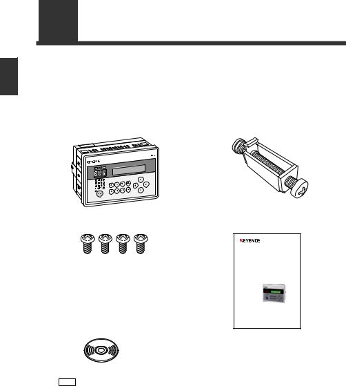
1-1 Checking the Package Contents
The package contains the following equipment and accessories.
Before using the DV-90, check that the following items are all included.
DV-90NE (NPN open collector output type)
DV-90NE main unit…1 |
Panel mounting bracket…4 |
Mounting screw (M4 tapping screw)…4 |
User’s Manual…1 |
AutoID Data Controller
DV-90
User’s Manual
Read this manual before using the system in order to achieve maximum performance. Keep this manual in a safe place for future reference.
CD-ROM…1
(Included software)
• DV-90 SetUp Software ( Refer to 7-2)
• USB driver ( Refer to 3-13)
• BL Series SetUp Software
Note Refer to the User’s Manual of the BL Series.
DV-90PE (PNP open collector output type)
DV-90PE main unit .................................... |
1 |
Panel mounting bracket ............................. |
4 |
Mounting screw (M4 tapping screw) ......... |
4 |
CD-ROM ................................................... |
1 |
User’s Manual ............................................ |
1 |
1-2 |
E DV-90-IM |
|
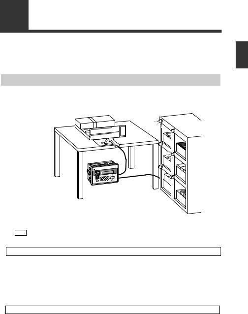
1-2 Overview of DV-90 Functions
Automated Product Selection at an Assembly Workstation
By reading the barcode attached to an assembly instruction sheet or a product in a high-mix lowvolume production line, the lamp on the shelf which contains the part to be assembled illuminates. By assembling the part stored on the illuminated shelf, assembly errors can be reduced.
1
Started Getting
Note |
The figure above is an example using a handheld reader. A fixed type reader can also be |
|
used. |
||
|
Use the “Normal Verification” function.  Refer to 4-4
Up to 900 presets be registered beforehand in the DV-90 as master data. The data read with the barcode reader is compared with the master data, and the corresponding preset number is output in parallel transmission.
In the above figure, the barcode on the assembly instruction sheet is preset in the DV-90. By connecting the parallel output after verification to a device such as a PLC, the corresponding lamp on the part shelf illuminates, thus preventing assembly errors.
Other uses
• Commanding operations to robots
By connecting the parallel output to a PLC for controlling a robot, the DV-90 can command the robot to perform specified operations.
•Switching the setting values of devices
The parallel output allows the setting values of the connected devices such as a weight checker to be changed automatically.
E DV-90-IM |
1-3 |
|

1
Started Getting
1-2 Overview of DV-90 Functions
Preventing Mixing with Other Products at a Packaging Machine
By reading the barcode printed on carton cases or cardboard cases at a packaging machine (carton packing machine or cardboard caser), the mispackaging of products in the wrong box can be prevented.
Use the “Active Verification” function.  Refer to 4-13
Up to 900 presets can be registered beforehand in the DV-90 as master data. The user selects a preset (the “active” record) for the particular line. When a product is scanned with a code reader, the data is compared to the active preset. A match turns on the OK output. Otherwise, the NG output is activated.
In the above figure, the barcodes printed on all the carton cases to be used are preset, and the carton case to be used for the next packaging is selected from among them. If the barcode of the selected carton case and the actually read barcode do not match, a lamp or buzzer notifies the operator that a wrong carton case is present.
An active record can be selected by any of the following methods:
•The DV-90 front panel buttons
•Reading the barcode you want to select
•From a PLC (PLC link  Refer to 9-4)
•Sending commands from a PC (Serial communication  Refer to 8-11)
Other uses
• Preventing mixing with other products at a labeling machine
Whether the correct label is attached to the product on a labeling machine can be checked.
• Preventing mixing of other products at a filling machine
On a filling machine that fills beverages, cosmetic creams, or seasonings, whether the content is filled in the correct container can be checked.
1-4 |
E DV-90-IM |
|

1-2 Overview of DV-90 Functions
Preventing Misplacement of Raw Material
1
Reading the barcodes on a batch instruction sheet and raw material package before adding the raw material ensures product uniformity.
Started Getting
Use the “Step Verification” function.  Refer to 4-17
The barcode data initially read and the data read next are compared, and Match/No match (OK/NG) is output.
In the above figure, the barcode on the batch sheet is read first, and then the barcode on the material is read. If they do not match, a lamp or buzzer notifies the operator.
Other uses
•Preventing mixing of chemical bottles on a semiconductor production machine
Checking whether the barcodes on the chemical bottle before replacement and on the new chemical bottle after replacement prevents potentinally dangerous or damaging mix-ups from occurring.
E DV-90-IM |
1-5 |
|
1-2 Overview of DV-90 Functions
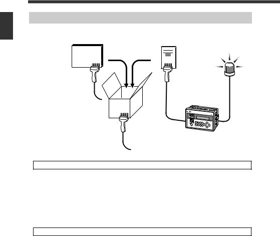
Preventing Mispackaging in a Manual Packaging Process
1
Reading the barcodes on the packaging case, product, and user’s manual in a manual packaging process prevents the packaging of a wrong product or user’s manual.
Started Getting
Use the “3 Points Verification” function.  Refer to 4-21
By bundling three barcode data as one set, up to 900 sets of master data can be registered (preset) in the DV-90. If the combination of the three read barcodes is correct, an OK output turns on. Otherwise, an NG output turns on.
In the above figure, all the combinations of the barcodes on the packaging case, product, and user’s manual are preset. The operator reads the barcodes in the order of the packaging case > product > user’s manual. If the barcode of the wrong product or user’s manual is read, a lamp or buzzer notifies the operator.
Other uses
•Preventing misplacement of chip reels on a chip mounting machine
Misplacement of the chip reel can be prevented by checking whether the barcode on the old chip reel, the one on the new chip reel, and the one on the placement location all match.
1-6 |
E DV-90-IM |
|

1-2 Overview of DV-90 Functions
Verifying the Assembly Instruction by Comparing with the Customer Order Sheet (Kanban)
In the process of assembling products such as automobile parts, by reading the barcodes on the assembly instruction, product, and the customer order sheet (Kanban), the part to be assembled can be specified and also you can check whether the assembly instruction and the customer order sheet (Kanban) match.
Use the “Picking Verification” function.  Refer to 4-28
By bundling three barcode data as one set, up to 900 sets of master data can be registered (preset) in the DV-90. Three barcodes are read in a row, and the output No. corresponding to the master data that matches each of one of the barcodes is output in parallel transmission.
Eventually, when all the preset barcodes in a set match the master data, an OK output turns on. Otherwise, an NG output turns on.
Let’s look at the example shown above.
First of all, preset all the combinations of the barcode data of the assembly instructions, products, and the customer order sheet (Kanban) prepared for today’s production.
When the assembly operator reads the barcode on the assembly instruction, the lamp on the shelf that contains the products to be manufactured illuminates. The operator places the indicated product on the workbench. Then, when the operator reads the barcode on the product, the lamp on the shelf that contains the part to be assembled on that product illuminates. The operator can then take the indicated part and assemble it on the product.
Finally, the operator reads the barcode (Kanban) on the customer order sheet. If the assembly operation has been done properly, an OK output turns on. Otherwise, an NG output turns on.
1
Started Getting
E DV-90-IM |
1-7 |
|

1-2 Overview of DV-90 Functions
Checking the Print Quality of the Expiration Date or Manufactured Date
1
Whether the expiration date or manufactured date in the barcode that includes it is correct can be checked.
Started Getting
Use the “Date Comparison” function.  Refer to 5-10
The DV-90 extracts the data that indicates the expiration date in the barcode, and compares it with the calendar in the DV-90. If the date is incorrect, or the date has expired, an NG output turns on.
Checking the Barcode Print Quality at the Printing Process
The printing quality of barcodes can be checked while they are being printed.
Use the “Reading Quality Judgment” function.  Refer to 5-14
The reading stability of the barcode reader connected to the DV-90 can be checked.
Set the reference value of the reading stability. When the actual reading stability drops below the reference value, “Reading Quality Judgment Output (QUALITY)” turns on. This allows you to determine the reading stability.
1-8 |
E DV-90-IM |
|
1-3 DV-90 Layout
Panel side
DV-90
|
OK |
NG |
ERR |
|
|
|
|
|
|
|
12 |
11 |
10 |
9 |
|
8 |
7 |
6 |
5 |
|
|
|
|
|
4 |
3 |
2 |
1 |
TRG1 |
|
TRG2 |
|
 PRESET
TEST TRG EDIT FNC
MENU DEL ESC
Record No. indicator LEDs ........... |
Display the record No. being registered, matched record |
|
|
|
No., and the reading rate of the code reader. |
Parallel input/output LEDs ............ |
Display the ON/OFF status of the parallel input/output. |
|
LCD display ....................................... |
|
Displays the read data, menu settings and error |
|
|
messages. |
Preset LED ......................................... |
|
Illuminates during the preset mode. |
Preset key .......................................... |
|
Used to register master data (preset). |
Operation keys ................................. |
|
Used for adjusting DV-90 settings. |
|
|
|
Key |
|
Usage |
|
Used for selecting the setting items or record No. displayed in the LCD |
|
|
display. |
|
|
|
|
MENU |
Used for changing the settings of the DV-90. |
|
|
|
|
TEST |
Used for the read test, code type check, and reading quality setting. |
|
|
|
|
|
Used for confirming the setting items and executing the functions. |
|
|
|
|
DEL |
Used for deleting master data, and deleting a character from the input data. |
|
|
|
|
ESC |
Used for canceling a menu and the like. |
|
|
|
|
EDIT |
Used for correcting the master data. |
|
|
|
|
FNC |
Used for executing a special function. |
|
|
|
|
TRG |
Performs a trigger input to the code reader by key operation. |
|
|
|
|
1
Started Getting
E DV-90-IM |
1-9 |
|
1
Started Getting
1-3 DV-90 Layout
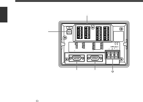
Terminal side
|
|
|
|
|
|
|
|
|
1 |
|
8 |
|
15 |
|
23 |
|
2 |
|
9 |
|
16 |
|
24 |
3 |
|
10 |
|
17 |
|
25 |
|
|
4 |
|
11 |
|
18 |
|
26 |
|
5 |
|
12 |
|
19 |
|
27 |
|
6 |
|
13 |
|
20 |
|
28 |
|
7 |
|
14 |
|
21 |
|
29 |
|
|
|
|
|
22 |
|
30 |
1 |
TRG 1 |
8 |
REMOTE |
15 |
READ_ERR |
23 |
OUT6 |
2 |
TRG 2 |
9 |
COM2 |
16 |
QUALITY |
24 |
OUT7 |
3 |
COM 1 |
10 |
UNLOCK |
17 |
COM5 |
25 |
OUT8 |
4 |
+24V |
11 |
COM3 |
18 |
OUT1 |
26 |
OUT9 |
5 |
0V |
12 |
OK |
19 |
OUT2 |
27 |
OUT10 |
6 |
+24V |
13 |
NO |
20 |
OUT3 |
28 |
OUT11 |
7 |
0V |
14 |
COM4 |
21 |
OUT4 |
29 |
OUT12 |
|
|
|
|
22 |
OUT5 |
30 |
COM6 |
PORT 2 |
|
|
PORT 1 |
|
|
||
|
|
|
|
|
|
11 |
|
USB port ............................................ |
Connects to the USB port on a PC. |
I/O terminal block ............................ |
Consists of parallel input and output terminals. The |
|
trigger input corresponding to the connected BL Series |
|
is connected here. |
RS-232C (PORT1) ........................... |
Connects to a code reader. |
RS-232C (PORT2) ............................ |
Connects to a PC, code reader or other approved device. |
11 Power terminal ................................. |
Connects to a 24V DC power supply unit. |
1-10 |
E DV-90-IM |
|
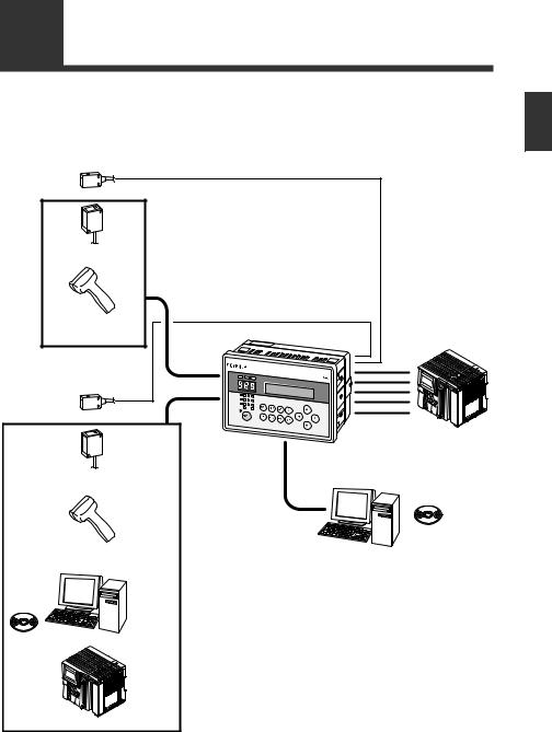
1-4 System Configuration and Connectable Devices
The DV-90 can be used with the following devices.
Numbers in parentheses ( ) are described on the following page.
1
Photoelectric switch |
|
Barcode |
|
fixed reader ( 5) |
|
Barcode |
|
handheld reader ( 5) |
DV-90 |
|
PORT1( 1) |
Photoelectric switch |
PORT1( 2) |
I/O( 4) |
|
Barcode/2D code |
USB( 3) |
|
|
fixed reader ( 5) |
|
Barcode/2D code
handheld reader ( 5) PC
RS-232C
SetUp |
PC |
|
Software |
|
|
( 6) |
|
|
|
B16XA |
RS-232C |
|
|
Started Getting
B16XA |
PLC
SetUp
Software
( 6)
PLC ( 7)
E DV-90-IM |
1-11 |
|

1
Started Getting
1-4 System Configuration and Connectable Devices
1 PORT1 can connect a barcode reader.
2 PORT2 can connect either a barcode reader, PC or PLC.
3 USB can connect a PC.
The supported operating systems are Windows 8/7/Vista/XP/2000.
4 The I/O terminal has 4 input pins and 16 output pins.
The NPN open collector output type (DV-90NE) and the PNP open collector output type (DV-90PE) are available for output.
5 The barcode readers that can be directly connected to PORT1 or PORT2 are the BL-700/600/ 180 Series, HR-40RK/50RK, and BL-210RK/N70RKE. For the BL-1300 Series, SR Series, TL-800/70R, and HR-30R/HR-UC51, a connector cable must be prepared separately.
The barcode reader directly connected to PORT1 or PORT2 are powered from the connected port. The maximum +5V DC power current that can be supplied to PORT1 and PORT2 is 1100 mA in total. Ensure that the power consumption of the connected barcode reader stays under this limit.
However, when the ambient temperature exceeds 40 °C, the maximum power current that can be supplied is 850 mA.
6 The SetUp Software is used when changing the internal settings of the DV-90. The settings can be changed on the PC that is connected to USB or PORT2.
7 In the communication with a PLC, non-procedural communication (An RS-232C unit that can establish non-procedural communication is required on the PLC side. Consult with the PLC manufacturer.) or communication by the dedicated protocol for the PLC manufacturer (PLC link) is available.
The following models of PLC are available for PLC link.
Keyence KV Series
Mitsubishi Electric MELSEC Series
Omron SYSMAC Series
Connectable combinations
Since PORT1, PORT2, and USB function independently, the connecting devices can be opted for independently as well.
The following list shows the connectable combinations.
PORT1 |
PORT2 |
USB |
Code reader |
- |
- |
|
|
|
Code reader |
PC |
- |
|
|
|
Code reader |
- |
PC |
|
|
|
Code reader |
PC |
PC |
|
|
|
Code reader |
PLC |
- |
|
|
|
Code reader |
PLC |
PC |
|
|
|
Code reader |
Code reader |
- |
|
|
|
Code reader |
Code reader |
PC |
|
|
|
1-12 |
E DV-90-IM |
|

2
2
Initial Setup of the Code Reader
This chapter describes the basic setup for connecting a code reader to the DV-90.
2-1 |
Code Reader Setup Basics ..................................................... |
2-2 |
2-2 |
Setting Procedure of the BL Series and the SR Series .......... |
2-6 |
2-3 |
Read Test Procedure of the BL Series and the SR Series...... |
2-8 |
2-1

2
Reader Code the of Setup Initial
2-1 Code Reader Setup Basics
This section describes the preparation flow before using the DV-90.
Reference
Note
2-2
1 In the settings of the DV-90, select "CR1 Type" in "Main".
Specify the type according to the code reader to connect.
Code reader model name |
Type |
|
BL-1300/700/600/180 Series |
Type A |
|
HR-50RK/40RK/UC51 |
Type B |
|
BL-N70RKE/N9R |
||
|
||
TL-800, TL-70R |
Type C |
|
BL-210RK |
Type D |
|
SR Series, HR-100 |
Type E |
|
|
|
|
Other code readers |
Others |
(Setting procedure)
(1)Press the MENU key for one second to enter the setting mode.
(2)Select “1 Main” and press the  key.
key.
(3)Press the  key twice to display “03 CR1 Type”.
(4)Press the  key to display a cursor.
(5)Select “TypeA,B,C,D,E, or Others”, and press the  key.
key.
(6)Press the ESC key twice to exit the setting mode.
By specifying the code reader type, the settings such as the default values of the communication setting of the DV-90 and pin assignment of PORT1 are modified to suit the specified code reader.
2 Configure the settings of the connecting code reader as follows.
If the code reader is at default, no setting change is required.
<BL-1300/700/600/180 Series, HR-50RK/40RK/UC51, BL-210RK/N70RKE/N9R>
• |
Baud rate : 9600 bits/s |
• |
Data length |
: |
7 bits |
||||||
• |
Parity |
: Even |
• |
Stop bit length : |
1 bit |
||||||
• Header |
: None |
• Terminator |
: |
|
CR |
or |
CR |
LF |
|||
• Communication protocol : No hand shaking |
|
|
|
|
|
|
|
||||
<TL-70R> |
|
|
|
|
|
|
|
|
|
|
|
• |
Baud rate : 9600 bits/s |
• |
Data length |
: |
8 bits |
||||||
• |
Parity |
: None |
• |
Stop bit length : |
1 bit |
||||||
• Header |
: None |
• Terminator |
: |
CR |
or |
CR |
LF |
||||
• Communication protocol : No hand shaking |
|
|
|
|
|
|
|
||||
<SR Series, HR-100> |
|
|
|
|
|
|
|
|
|
||
• |
Baud rate : 115200 bits/s |
• Data length |
: 8 bits |
||||||||
• |
Parity |
: Even |
• Stop bit length |
: 1 bit |
|||||||
• |
Header |
: None |
• Terminator |
: |
CR |
|
|||||
•Communication protocol : No hand shaking
•If the setting cannot be changed on the code reader side, adjust the DV-90 settings for “PORT1” in the setting mode of the DV-90. (  Refer to 6-8.)
•If you are using the BL-1300/700/600/180 and the code reader setting cannot be checked, the DV-90 can detect it automatically.
Refer to page 2-5 for automatic detection.
E DV-90-IM
2-1 Code Reader Setup Basics
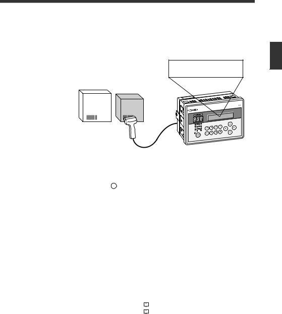
3 Connect the code reader to PORT1 of the DV-90.  Refer to 3-8.
Turn off the power of the DV-90 when connecting the code reader.
4 Read the data with the code reader, and confirm that the data is displayed on the |
2 |
|
LCD of the DV-90. |
||
|
||
1 2 3 4 5 6 7 8 9 0 |
|
|
|
Reader Code the of Setup Initial |
•If you are using the BL-1300/700/600 or the SR Series, the data can be read by gently pressing the [TEST] switch on the DV-90 once.
•If you are using the BL-180, perform the following key operations on the DV-90. (The same operations are valid on the BL-1300/700/600 and the SR-600/500.)
(1)Press the TRG key on the DV-90.
(2) Select “CR1” by pressing the  key on the DV-90.
(3) Press the  key on the DV-90 and reading starts.
5 Change the code reader settings (such as the type of barcode to read).
•For the HR-50RK/40RK/UC51, BL-210RK/N70RK/N9R, and TL-800/70R, refer to the respective manuals to change the settings.
•For the BL-700/600/180 Series, configure the settings on the BL SetUp Software.
 Refer to “BL Series User’s Manual”.
•The settings are made on Auto ID Navigator for the BL-1300 and the SR-600/500.
 Refer to “BL-1300 Series and SR Series User's Manual”.
6 According to the purpose of use, change the settings of the DV-90.
The settings of the DV-90 can be changed in the following methods.
• |
Key operations on the DV-90 |
|
|
Refer to 6-1. |
|
||||
• |
DV-90 SetUp Software |
|
|
Refer to 7-1. |
|
E DV-90-IM |
2-3 |
|

2
Reader Code the of Setup Initial
2-1 Code Reader Setup Basics
7 Wire the trigger input (input to starting reading).  Refer to 3-4.
•If a hand-held reader is connected, no wiring is required.
•For the BL-1300/700/600/180 Series and the SR-600/500, wire the trigger input to the DV90.
8 Wire the I/O terminals.  Refer to 3-2.
9 If you want to communicate with a device such as a PC or a PLC, connect the DV-90 to the device.  Refer to 3-10.
For the communication control and operation methods according to the connected device, refer to the following pages.
• |
PC (serial communication) |
|
|
Refer to 8-1. |
|
||||
• |
PLC (PLC link) |
|
|
Refer to 9-1. |
|
10 Use the DV-90 and confirm its operation is correct.
The DV-90 setup and connections is complete.
2-4 |
E DV-90-IM |
|
2-1 Code Reader Setup Basics
How to Detect the Communication Setting Automatically
When the communication setting of the connected BL-1300/700/600/500/180 Series cannot be checked, you can have the DV-90 detect it automatically.
Follow the steps below.
1 |
Press the MENU |
key for a second. |
|
|
|
|
|
|
|
|
|
|
|||
|
|
1 |
M a i n |
|
|||
|
The display enters the setting mode. |
|
|
2 |
V e r i f y |
|
|
2 |
|
|
|
|
|
|
|
|
|
|
|
|
|||
Select “3 PORT1” by pressing the |
key |
|
|
P O R T 1 |
|
||
3 |
|
||||||
|
twice. |
|
|
|
4 |
P O R T 2 |
|
3 |
Press the |
key. |
|
|
|
|
|
|
|
|
|
||||
|
|
0 |
1 C o m m . c o n f i g |
||||
|
|
|
|
|
0 |
: M a n u a l |
|
4 |
|
|
|
|
|
|
|
|
|
|
|
|
|||
Press the |
key, and then press the |
key. |
|
0 |
1 C o m m . c o n f i g |
||
|
|
|
|
|
1 |
: A u t o |
|
5 |
|
|
|
|
|
|
|
|
|
|
|
|
|||
Press the |
key and the automatic detection |
|
0 |
1 1 A u t o |
C o n f i g |
||
|
starts. |
|
|
|
|
C a n c e l - E S C |
|
|
The screen to the right is displayed during the auto detec- |
|
|
|
|
||
|
|
|
|
|
|||
|
tion. |
|
|
|
|
|
|
6 |
|
|
|
|
|||
The result is displayed when the detection is |
|
0 |
1 1 A u t o |
C o n f i g |
|||
|
completed. |
|
|
|
|
: 9 6 0 0 |
/ 7 e 1 |
|
When the detection has failed, the screen to the right |
|
|
|
|
||
|
|
|
|
|
|||
|
|
0 1 1 A u t o C o n f i g |
|||||
|
is displayed. |
|
|
|
|||
|
|
|
|
|
: ? ? ? ? ? ? ? × |
||
|
|
|
|
|
|
||
7 |
Press the |
key and the detected setting is |
|
|
|
||
|
confirmed. |
|
|
|
|
|
|
8 |
Press the ESC |
key twice to exit the setting mode. |
|
|
|||
The automatic detection is completed.
2
Reader Code the of Setup Initial
E DV-90-IM |
2-5 |
|

2
Reader Code the of Setup Initial
2-2 Setting Procedure of the BL Series and the SR Series
When changing the settings of theBL-1300/700/600/500/180 Series or the SR-600/500 Series, use the SetUp Software dedicated to the BL Series or AutoID Navigator. This section describes its procedure.
Setting Procedure Using the SetUp Software
1 Perform step 1 though 4 described in “2-1 Flow of Connections and Settings”.
2 Connect the PC to the USB port or PORT2 of the DV-90.
•To connect the PC to the USB port, the USB driver software for the DV-90 should be installed.  Refer to 3-13.
•When connecting the PC to PORT2  Refer to 3-10.
3 Start the SetUp Software and change the settings as desired.
For the operation procedures of the BL SetUp Software and AutoID Navigator, refer to the BL Series and SR Series User's Manuals.
4 Configure the DV-90 to establish direct communication between the code reader
and the PC.
(1) Pressing the TEST key on the DV-90 three times displays “Test Mode 3 PC Direct” for a second, and the screen to the right is displayed.
If “PORT2 Unit” is set to “Code Reader”, the CR1/CR2 selection screen appears. Select the one with which you want to communicate, and press
the  key.
key.
(2) Select the port of the DV-90 to which the PC is connected.
• When connected to USB Press  .
.
• When connected to PORT2 Press  .
.
(3) Press the  key.
key.
P C D i r e c t * C R 1 < >
P C D i r e c t
P O R T 2 < > U S B *
Note “PORT2” is not displayed at (2) if “PORT2 Unit” is not set to “PC”.
2-6 |
E DV-90-IM |
|
Loading...