


 Loading...
96M10106
High-speed, High-precision
Free-layout Static Elimination Blower


 300 Series
Instruction Manual
Before using this Free-layout Elimination Blower, be sure to thoroughly read this Instruction Manual. After you are finished with this Instruction Manual, be sure to store it in a safe place for quick reference.
1
Preface
This document describes handling, method of operation and precautions when using the High-speed, High-precision Free-layout Elimination Blower Unit SJ-F300 Series. Before you start to use the SJF300 Series, be sure to thoroughly read this document in order to make full use and safely use the functions of the SJ-F300 Series.
Store this document in a safe place so that you can retrieve it whenever necessary.
■ Symbols
This manual uses the following symbols to alert you to important information.
Be sure to read below.
Failure to follow these instructions may lead to death or serious injury.
DANGER
Failure to follow these instructions may lead to injury.
WARNING
CAUTION
Failure to follow these instructions may lead to physical damage (product malfunction, etc.).
Important:
Provides additional information on precautions and restrictions that must be followed in operation.
Note:
Provides additional information on proper operation.
Tip Indicates useful information or information that aids understanding of text descriptions.
Indicates a reference item or page to be referred to in this manual and a separate manual.
Safety Precautions
■ General Precautions
CAUTION
• At startup and during operation, be sure to monitor the functions and performance of the SJ-F300 Series.
•We recommend that you take substantial safety measures to avoid any damage in the event that a problem occurs.
•Do not modify the SJ-F300 Series or use it in any way other than described in the specifications. The functions and performance of products used or modified in this way cannot be assured.
•When the SJ-F300 Series is used in combination with other instruments, functions and performance may be degraded, depending on operating conditions and the surrounding environment.
•Do not use the SJ-F300 Series for the purpose of protecting the human body.
■SJ-F300 Series Handling Precautions
The SJ-F300 Series is a high-voltage product that is not designed in an explosion-proof structure. Pay attention to the following when using the SJ-F300 Series.
WARNING
• To prevent electric shock and to ensure accurate static elimination, be sure to connect a Class D earth (maximum resistance of 100 Ohms).
•Do not use this product in locations where there is the risk of ignition or explosion from flammable solvents or dirt and dust.
•High voltage is applied to this product. Prevent it from being splashed with water, oil, or flammable solvents. Failure to do so may cause insulation breakdown, which will result in electric shock or malfunction.
•Do not bring your fingers or tools, wire or other metallic objects near this product. Doing so may cause electric shock or malfunction.
•Do not use this product in a non-ventilated location. The ozone generated from this product may become toxic. Be sure to ventilate the installation site when this product is used in a non-ventilated location.
•Do not use this product in locations where sudden changes in temperature or condensation are likely to occur. Doing so may cause accidents or malfunction.
•Do not operate this product with wet hands. Doing so may cause electric shock.
•Before starting maintenance, be sure to turn the power OFF. Failure to do so may result in electric shock or accidents.
•During maintenance, do not directly touch the electrode needles. Doing so may cause personal injury.
•If any malfunction is observed in this product, immediately turn it OFF, and contact your nearest agent. You should never repair this product yourself. Doing so may cause electric shock or malfunction.
CAUTION Do not touch the electrode needles with a tool or other hard object. Damage to the electrode needles will prevent static elimination performance from being fully demonstrated, and cause accidents or malfunction.
CAUTION
• When this product is used for a long period of time, the electrode needles become dirty due to the adhesion of dust and dirt. If the ion level alarm indicator or condition alarm indicator lights, clean the electrode needles. If the electrode needles are used in a dirty or dusty state, the static elimination performance can no longer be fully demonstrated, resulting in accidents or malfunction. We recommend periodically cleaning the electrode needles (as a guideline, once every two weeks in a regular operating environment though this depends on the installation conditions).
• Do not drop or subject this product to shock. Doing so may result in accidents or malfunction.
• Use this product for static elimination only. Do not use it for other purposes.
■ Power Supply Precautions
CAUTION
• Use a DC power supply with rated 24 V output.
• Noise applied to the power supply may cause this product to malfunction. If this happens, install an insulated transformer.
• When using a switching regulator, be sure to connect a Class D earth to the
Frame Ground terminal.
■ Grounding Precautions
CAUTION
• To ensure safety and appropriate static elimination, be sure to ground this product.
•Be sure to connect a Class D earth (maximum resistance of 100 Ohms).
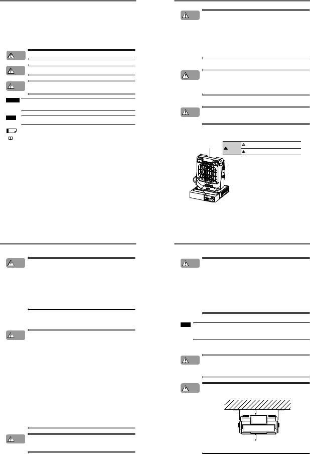
■SJ-F300 Series Warning Label
A WARNING label is affixed on the SJ-F300 Series to ensure safety.
Read the description on this WARNING label to ensure correct use of the SJ-F300 Series.
Be sure to turn the power off when replacing

 WARNING
the electrode probes. Otherwise, electric shock may occur.
Do not touch electrode probes with your hands or fingers, as this may cause injury.
* WARNING labels in Japanese, German, French, Italian and Chinese:SC are provided.
Use them as necessary.
■ Installation Precautions
CAUTION
Avoid installing the SJ-F300 Series in the following locations as this may cause accidents.
•Locations directly subject to vibration and shock
•Locations subject to ambient temperature out of the 0°C to +50°C range
•Locations subject to ambient humidity out of the 35 to 65%RH range (condensation not allowed)
•Locations subject to sudden changes in temperature
•Locations subject directly from blasts from air conditioners
•Locations subject to volatile or flammable substance, solvents or corrosive gases
•Locations subject to large amounts of dirt, and dust, salt, iron and oil smoke
•Locations that may be splashed with water, oil or chemical mist
•Locations where strong magnetic and electrical fields are generated
■About Warming Up the SJ-F300 Series
Note:
Leave the SJ-F300 Series for about 20 minutes after turning the power ON to allow the ion balance to stabilize.
The ion balance may be unstable during this warming up period.
■ Other Precautions
CAUTION • Be sure to read the WARNINGS and CAUTIONS described in each of the items in this Instruction Manual.
•The Static Elimination Blower Unit has a built-in EEPROM. Do not turn the Static Elimination Blower Unit OFF during the setup.
CAUTION Refer to the following diagram when installing the SJ-F300 Series.
• Install the Static Elimination Blower Unit away from the wall or surrounding objects.
50 mm or more
50 mm or more
•Install the Static Elimination Blower Unit so that the Electrode Unit can be removed for replacement.
1
Precautions on Regulations and Standards
■ CE Marking
Keyence Corporation has confirmed that this product complies with the essential requirements of the applicable EC Directive, based on the following specifications.
Be sure to consider the following specifications when using this product in the Member State of European Union.
● EMC Directive (2004/108/EC)
• Applicable standard |
EN61326-1 |
•Be sure to provide a ground when installing the SJ-F300 Series.
•The length of cable (power lead and I/O leads) must be less than or equal to 30 m.
Remarks:
These specifications do not give any guarantee that the end-product with this product incorporated complies with the essential requirements of EMC Directive. The manufacturer of the end-product is solely responsible for the compliance on the end-product itself according to EMC Directive.
●Low-Voltage Directive (2006/95/EC)
•Applicable Standard : EN61010-1
•Overvoltage category I
•Use this product under pollution degree 2.
•Use the power supply for the SJ-F300 Series, that satisfies the requirements of the Limited Power Source specifications stipulated in EN60950-1 and certified by European third-party certification organization, or a Keyence Corporation AC adapter (SJ-U2). The specifications of the AC adapter (SJ-U2) are as follows.
•When connecting to an SJ-U2, be sure to use a power cable compliant with European standards. Applicable standard: EN60950-1
Overvoltage category II Pollution degree 2
•Be sure to provide a ground when installing the SJ-F300 Series.
1-1 System Configuration
This section describes the system configuration of the Static Elimination Blower Unit SJ-F300 Series.
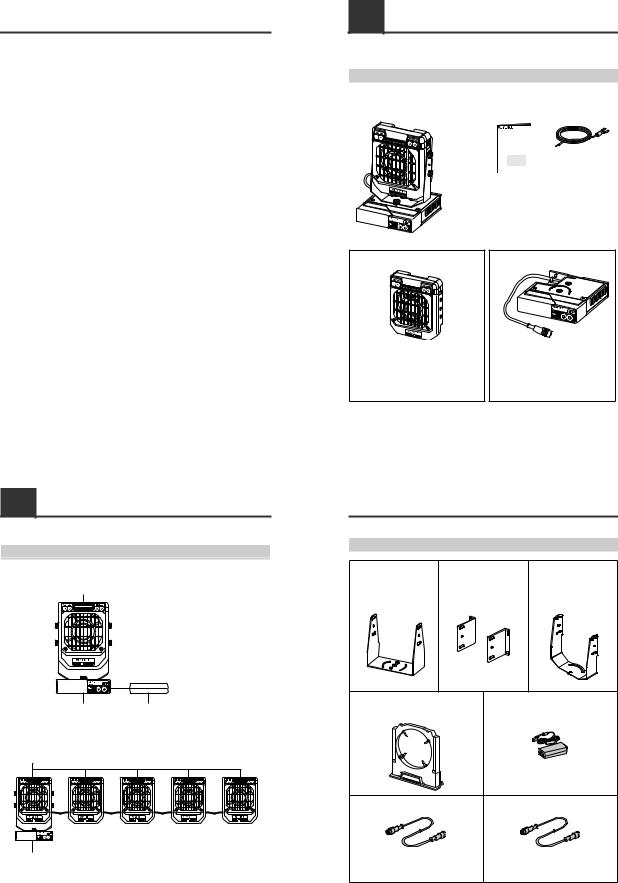
System Configuration
■ When used independently
Static Elimination Blower Unit


 to AC power
Controller Unit |
AC adapter |
■ When used in connection
Maximum number of the Static Elimination Blower Units connectable to one Controller Unit is five.
Static Elimination Blower Units

 to 24 VDC power
Controller Unit
1-2 Checking the Contents of the Package
The package contains the following components and accessories. Before getting started, make sure that the package contains everything that it is supposed to contain.
Package Contents
■ When you purchased as a set
• Body |
• Instruction Manual |
• Earth lead |
High-speed, High-precision
Free-layout Static Elimination Blower
SJ-F 300 Series
Instruction Manual
Attached to the main unit when shipped from the factory.
• Warning label (Japanese, German, French, Italian, Chinese: SC)
* Use as necessary.
■ When you purchased independently
• Static Elimination Blower Unit (SJ-F030/F035) |
• Controller Unit (SJ-F300) |
• Warning label |
• Earth lead |
(Japanese, German, French, Italian, Chinese: SC) |
|
*Use as necessary.
*When purchased the Static Elimination Blower
Unit independently, note that a mounting fixture |
• Instruction Manual |
is not included. |
|
|
|
|
|
1-2 |
Checking the Contents of the Package |
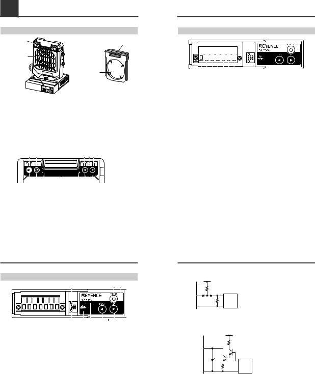
Options |
|
|
|
|
|
Mounting fixture A (OP-78476) |
Mounting fixture B (OP-78477) |
Mounting fixture C (OP-78478) |
|||
Accessory: M4 screw for fixing |
Accessory: |
M4 screw for fixing |
Accessory: M4 fixing screw x 6 |
||
|
the Static |
|
the Static |
|
|
|
Elimination Blower |
|
Elimination Blower |
|
|
|
Unit x 4 |
|
Unit x 4 |
|
|
Electrode Unit for exchanging (OP-51407) |
AC adapter (SJ-U2) |
||||
|
|
|
Capable of driving up to one fan. |
||
|
|
|
For details of the AC cable, contact the KEYENCE |
||
|
|
|
sales office in your district. |
||
Controller-Blower extension cable * |
|
Blower-Blower extension cable * |
|||
SJ-C2J |
Plug-Jack at both ends 2 m |
|
SJ-C02P Plug-Plug at both ends 0.2 m |
||
SJ-C5J |
Plug-Jack at both ends 5 m |
|
SJ-C2P |
Plug-Plug at both ends 2 m |
|
SJ-C10J Plug-Jack at both ends 10 m |
SJ-C5P |
Plug-Plug at both ends 5 m |
|||
|
|
|
SJ-C10P Plug-Plug at both ends 10 m |
||
*• Total cable length cannot exceed 20 m.
(One unit: 20 m, Two units: 15 m, Three units or more: 10 m)
•To connect the blowers with a cable other than that of 2, 5 and 10 m, use the blower-blower extension cable (SJ-C * P) in combination with a controller-blower extension cable (SJ-C * J).
2
1-3 Names and Functions of Parts
Static Elimination Blower Unit
Static elimination blower
unit operation panel |
Lock switch |
|
Electrode Unit |
||
|
||
Fan guard |
|
|
|
Electrode needle |
Electrode Unit
Provided with the electrode needles. Remove from the Static Elimination Blower Unit before attempting maintenance and servicing work.
Refer to  "Performing Maintenance on the Electrode Needles" (page 9) for details about how to remove the Electrode Unit.
Electrode needle
Generates ions from its tip.
Lock switch
Fixes the Electrode Unit to the Static Elimination Blower Unit.
Fan guard
SJ-F030: Metal
SJ-F035: Resin
■ Operation panel
|
[1] |
|
[2] |
|
|
|
|
|
|
|
|
|
|
|
|
|
|
[3] [4] [5] |
|
|
||||||||||||||
|
|
|
|
|
|
|
|
|
|
|
|
|
|
|
|
|
|
|
|
|
|
|
|
|
|
|
|
|
|
|
|
|
|
|
|
|
|
|
|
|
|
|
|
|
|
|
|
|
|
|
|
|
|
|
|
|
|
|
|
|
|
|
|
|
|
|
|
|
|
|
|
|
|
|
|
|
|
|
|
|
|
|
|
|
|
|
|
|
|
|
|
|
|
|
|
|
|
|
|
|
|
|
|
|
|
|
|
|
|
|
|
|
|
|
|
|
|
|
|
|
|
|
|
|
|
|
|
|
|
|
|
|
|
|
|
|
|
|
|
|
|
|
|
|
|
|
|
|
|
|
|
|
|
|
|
|
|
|
|
|
|
|
|
|
|
|
|
|
|
|
|
|
|
|
|
|
|
|
|
|
|
|
|
|
|
|
|
|
|
|
|
|
|
||||||||||||||||
|
|
|
|
|
|
|
|
|
|
|
|
|
|
|
|
|
|
|
|
|
|
|
|
|
|
|
|
|
|
|
|
|||
|
|
[7] |
|
[8] |
|
|
[6] |
|
|
|
|
[9] |
|
|
||||||||||||||||||||
|
|
|
|
|
|
|
|
|
|
|
|
|
|
|
|
|
|
|
|
|
|
|
|
|
|
|
|
|
|
|
|
|
|
|
[1] |
Ion level alarm indicator |
Lit OFF |
Normal |
|||||||||||||||||||||||||||||||
Blinking in red |
Ion level alarm has occurred. |
|||||||||||||||||||||||||||||||||
|
|
|
|
|
|
|
|
|
|
|||||||||||||||||||||||||
[2] |
Condition alarm indicator |
Lit OFF |
Normal |
|||||||||||||||||||||||||||||||
Blinking in red |
Condition alarm has occurred. |
|||||||||||||||||||||||||||||||||
|
|
|
|
|
|
|
|
|
|
|||||||||||||||||||||||||
[3] |
Ion balance indicator |
|
|
|
|
|
When lit, the indicator displays the ion balance. |
|||||||||||||||||||||||||||
[4] |
Ion level indicator |
|
|
|
|
|
When lit, the indicator displays the ion level. |
|||||||||||||||||||||||||||
[5] |
Blow rate indicator |
|
|
|
|
|
When lit, the indicator displays the blow rate setting value. |
|||||||||||||||||||||||||||
|
|
|
|
|
|
|
|
|
|
The monitor displays the ion balance, ion level, blow rate setting value in |
||||||||||||||||||||||||
[6] |
Monitor |
|
|
|
|
|
seven indication levels. |
|||||||||||||||||||||||||||
|
|
|
|
|
|
|
|
|
|
Lights in red when the Static Elimination Blower Unit needs cleaning. |
||||||||||||||||||||||||
[7] |
START/STOP key |
|
|
|
|
|
Used for switching start/stop. |
|||||||||||||||||||||||||||
[8] |
ENTER key |
|
|
|
|
|
Used for selecting various setups. |
|||||||||||||||||||||||||||
[9] |
UP/DOWN key |
|
|
|
|
|
Used for selecting and adjusting various setups. |
|||||||||||||||||||||||||||
1-3 Names and Functions of Parts
Controller Unit (Operation/Display Section)
[6] [1] [2]
|
|
|
|
|
|
|
|
|
|
|
|
|
|
|
|
|
|
|
|
|
|
|
|
|
|
|
|
|
|
|
|
|
|
|
|
|
|
|
|
|
|
|
|
|
|
|
|
|
|
|
|
|
|
|
|
|
|
|
|
|
|
|
|
|
|
|
|
|
|
|
|
|
|
|
|
|
|
|
|
|
|
|
|
|
|
|
|
|
|
|
|
|
|
|
|
[7] |
[5] |
[4] |
[3] |
|
|
|
|
||||||||
[1]Power switch ..... Used for turning ON/OFF the SJ-F300 Series.
[2]Power indicator ..... Displays the power condition ON/OFF.
Lit in green |
: Normal |
Lit OFF |
: Power OFF |
Blinking in green |
: Static elimination stop inputted. |
Blinking in red |
: Alarm has stopped. |
[3] Blow rate adjusting key ..... Used for adjusting the blow rate of the Static Elimination Blower Units being connected collectively.
[4] Ion level alarm indicator .....Blinks when the ion emission level has dropped below the setting value
|
due to dirt or wear of the electrode needles. |
Lit OFF |
: Normal |
Blinking in red |
: Ion level alarm has occurred. |
Blinking in red |
: Alarm has stopped. *1 |
Double blinking |
: Under ion balancing |
[5] Condition alarm indicator .... Blinks when the static elimination performance may be influenced by instability of the installation environment (temperature, humidity,
|
surrounding metal objects, etc.), for example, when ions are being |
|
absorbed by surrounding metal objects. |
Lit OFF |
: Normal |
Blinking in red |
: Condition alarm has occurred. |
Blinking in red |
: Alarm has stopped. *1 |
[6] Ion level alarm sensitivity setup switch ..... Used for changing the threshold value at which ion level alarm is output.
H: High sensitivity M: Medium sensitivity
L:Low sensitivity
[7]Condition alarm sensitivity setup switch ..... Used for changing the threshold value at which condition
|
|
alarm is output. |
|
H: High sensitivity |
|
|
M: Medium sensitivity |
|
|
L: Low sensitivity |
|
*1 |
Alarm level 2, 3: [2], [4] and [5] blink simultaneously in red. |
|
|
Alarm level 1: |
[2] blinks in red. |
1-3 Names and Functions of Parts
Controller Unit (I/O Terminal Section)
|
|
|
|
|
|
|
|
|
|
|
|
|
|
|
|
|
|
|
|
|
|
|
|
|
|
|
|
|
|
|
|
|
|
|
|
|
|
|
|
|
|
|
|
|
|
|
|
|
|
|
|
|
|
|
|
|
|
|
|
|
|
|
|
|
|
|
|
|
|
|
|
|
|
|
|
|
|
|
|
|
|
|
|
|
|
|
|
|
|
|
|
|
|
|
|
|
|
|
|
|
|
|
|
|
|
|
|
|
|
|
|
|
|
|
|
|
|
|
|
|
|
|
|
|
|
|
|
|
|
|
|
|
|
|
|
|
|
|
|
|
|
|
|
|
|
|
|
|
|
|
|
|
|
|
|
|
|
|
|
|
|
|
|
|
|
|
|
|
|
|
|
|
|
|
[1] |
[2] |
|
[3] [4] |
[5] |
[6] |
[7] |
|
|
|
|
|
|
|
|
|
|
|
|
|
|
|
|
|
|
|
|
|
|||||||
[1]Ground terminal ..... Be sure to connect a Class D earth.
[2]DC power terminal ..... 24 VDC ±10%
[3]0 V terminal ..... 0 V for power and 0 V for I/O
[4]Static elimination stop input terminal ..... Static elimination can be turned ON/OFF by shorting this
terminal with [3] or [5].
[5]0 V terminal ..... 0 V for power and 0 V for I/O
[6]Alarm output terminal ..... Outputs a signal when alarm condition has occurred.
[7]Condition/Ion level alarm output terminal .... Outputs a signal when the static elimination
performance may be influenced by instability of the installation environment, or when the ion emission level has dropped.
1-3 Names and Functions of Parts
■Input circuit diagram
[4]Static elimination stop input
+5 V |
|
|
Input zero-voltage contact (relay, etc.) or NPN open |
470 Ω |
collector to INPUT or 0 V. |
INPUT[4] |
|
10 kΩ |
Internal |
Circuit |
|
0 V[3], [5] |
|
■ Output circuit diagram
Open collector output
[6] Alarm output, [7] Condition/Ion level alarm output
|
|
5 V |
|
|
|
180 Ω |
|
OUTPUT[6], [7] |
|
|
|
40 VDC |
|
|
|
100 mA |
|
|
|
47 V |
|
|
|
4.7 |
Ω |
Internal |
|
Circuit |
|||
|
|
||
0 V[3], [5] |
|
|
3

2-1 Before Installation
Before you install this product, examine carefully the distance between the Static Elimination Blower Unit and the target object and the time required for static elimination.
About Static Elimination Performance
The following shows a typical example where static is eliminated from an aluminum plate (20 pF) 150 mm x 150 mm square charged to +1000 V by this product.
The blow rate of the blower is set at maximum (FAST).
■ Static elimination area
The following graphs show the relationship between the time required for eliminating static from a target object charged from +1000 V to +100 V and the distance from the charged object up to the Static Elimination Blower Unit.
200 |
400 |
600 |
|
800 |
1000 |
1200 |
1400 |
1600mm |
200 |
400 |
600 |
800 |
1000 |
1200 |
1400 |
1600mm |
600mm |
|
|
|
|
|
|
|
|
600mm |
|
|
|
|
|
|
|
1s |
2s |
3s |
4s |
5s |
|
|
|
|
|
1s |
|
2s |
3s |
4s |
5s |
|
0 |
|
|
|
|
|
|
|
|
0 |
|
|
|
|
|
|
|
SJ-F030 |
|
|
|
|
|
|
|
|
SJ-F035 |
|
|
|
|
|
|
|
600mm |
|
|
|
|
|
|
|
|
600mm |
|
|
|
|
|
|
|
■ Static elimination time
The following graphs show the relationship between the time required for eliminating static at the maximum blow rate from a target object charged at +1000 V positioned 300 mm apart from the Static Elimination Blower Unit and the charged level.
|
1 |
|
|
|
|
|
|
|
|
|
|
1 |
|
|
|
|
|
|
|
|
(kV) |
0.8 |
|
|
SJ-F030 |
|
|
|
|
|
(kV) |
0.8 |
|
|
SJ-F035 |
|
|
|
|
||
0.6 |
|
|
|
|
|
|
|
|
|
0.6 |
|
|
|
|
|
|
|
|
||
level |
0.4 |
|
|
|
|
|
|
|
|
|
level |
0.4 |
|
|
|
|
|
|
|
|
|
|
|
|
|
|
|
|
|
|
|
|
|
|
|
|
|
||||
Charged |
0.2 |
|
|
|
|
|
|
|
|
|
Charged |
0.2 |
|
|
|
|
|
|
|
|
|
0 |
|
|
|
|
|
|
|
|
|
|
0 |
|
|
|
|
|
|
|
|
|
-0.2 |
|
|
|
|
|
|
|
|
|
|
-0.2 |
|
|
|
|
|
|
|
|
|
0 |
1 |
2 |
3 |
4 |
|
|
0 |
1 |
2 |
3 |
4 |
||||||||
|
|
Time required for static elimination (sec) |
|
|
|
|
|
Time required for static elimination (sec) |
|
|
||||||||||
|
|
|
|
|
|
|
|
|
|
|
|
|
|
|
||||||
|
|
|
|
|
|
|
|
|
|
|
|
|
|
|
|
|
|
|
|
|
2-1 Before Installation
■ Appropriate static elimination method
Pay attention to the following points to ensure that static elimination is performed appropriately.
Static elimination cannot be performed accurately at locations where the target object is touching a metallic body (earthed body).
Eliminate static from the target body at locations where it is not directly touching metallic bodies (earthed body).
Static will be eliminated from only the surface of the insulated body (film, sheet, etc.) that is facing the Static Elimination Blower Unit.
When eliminating static from both sides of a target body, install two Static Elimination Blower Units as one unit must be installed on either side of the target body.
Film, sheet or other electrically charged object
NG |
Metal roller |
OK |
OK
Note:
Install the Static Elimination Blower Unit so that it can be easily accessed, for example, for replacement of parts and cleaning.
Installation Precautions
■ Installation site
Refer to the following diagram when installing the SJ-F300 Series.
• Install the Static Elimination Blower Unit away from the wall or surrounding objects.
50 mm or more
50 mm or more
•Install the Static Elimination Blower Unit so that the Electrode Unit can be removed for replacement.
■Interference
The Static Elimination Blower Unit may not function properly if two or more units are used close to each other. In such an installation, refer to the following diagram and maintain the indicated distance between units.
15 |
mm or |
|
|
more |
|
|
|
|
|
|
|
2-2 Connection and Installation
Installing the SJ-F300 Series
Install the SJ-F300 Series at locations where static electricity is generated or is likely to be generated. When installing the Static Elimination Blower Unit separately from the Controller Unit, refer to "■ Installing the Static Elimination Blower Unit" below.
■ Installing the Static Elimination Blower Unit
There are two ways of installing the Static Elimination Blower Unit, with or without the mounting fixtures. Each installation method is shown below.
●When using mounting fixture A (OP-78476):
1 Tap M4 screw holes where the Static Elimination Blower Unit is to be installed, and fasten mounting fixture A (OP-78476) with M4 screws.
You can adjust the horizontal angle of the Static Elimination Blower Unit by using the semi-circled cutout holes on the base of mounting fixture A.
M4 screws for fastening mounting fixture A at the installation location must be provided separately.
M4 screws
2Install the Static Elimination Blower Unit on mounting fixture A.
You can adjust the vertical angle of the Static Elimination Blower Unit by using the semi-circled cutout holes on the base of mounting fixture A.
M4 screws for fastening mounting fixture A to the Static Elimination Blower Unit are provided with mounting fixture A.
M4 screws
 M4 screws
Tip When using the accessory mounting fixture, also fasten it with screws as shown above.
2-2 Connection and Installation
●When using mounting fixture B (OP-78477):
1 Install mounting fixture B (OP-78477) on the Static Elimination Blower Unit.
M4 screws for fastening the Static Elimination Blower Unit to mounting fixture B are provided with mounting fixture B.
M4 screws
M4 screws
2Tap M4 screw holes where the Static Elimination Blower Unit is to be installed, and fasten mounting fixture B (OP-78477) with M4 screws.
M4 screws for fastening mounting fixture B to the installation location must be provided separately.
M4 screws
3Loosen the screws mounted on the Static Elimination Blower Unit, and adjust the installation angle. Then, fasten with the screws again.
● When mounting fixtures are not used:
Drill holes of diameter 4.2 mm or more at the location where the Static Elimination Blower Unit is to be installed, and fasten with M4 screws.
M4 screws must be provided separately.
M4 screws
M4 screws 


4
Loading...