


 Loading...
427GB
PROFINET Communication Unit
DL-PN1 (IB)
User's Manual
Read this manual before use.
Keep this manual in a safe place for future reference.
Introduction
This manual describes the basic operations and hardware functions of the DL-PN1. Read the manual carefully to ensure safe performance and function of the DL-PN1. Keep this manual in a safe place for future reference.
Ensure that the end user of this product receives this manual.
Symbols
The following symbols alert you to matters concerning the prevention of injury and product damage.
|
|
|
It indicates a hazardous situation which, if not avoided, could result in |
|
WARNING |
||
|
|
death or serious injury. |
|
|
|
|
|
|
|
|
|
|
|
|
It indicates a hazardous situation which, if not avoided, could result in |
|
CAUTION |
||
|
|
minor or moderate injury. |
|
|
|
|
|
|
|
|
|
|
NOTICE |
|
It indicates a situation which, if not avoided, could result in product |
|
|
damage as well as property damage. |
|
|
|
|
|
|
|
|
|
|
|
|
|
 Important It indicates cautions and limitations that must be followed during operation.
Point It indicates additional information on proper operation.

 Reference It indicates tips for better understanding or useful information.

Overview of PROFINET
What is PROFINET?
PROFINET is an open industrial networking standard developed and maintained by the PI (PROFINET International).
All supported devices can use the communication network regardless of the vendor. PROFINET allows easy integration with the currently used field bus (such as PROFIBUS), enabling you to protect the existing assets without modifying the legacy system.
The PROFINET communication for the DL-PN1 series supports the PROFINET I/O communication, which transmits data between I/O controllers (PLC etc.) and I/O devices, and complies with Conformance Class A.
The PROFINET I/O communication offers the following two types of communication methods for cyclic data: Real-time communication (RT) and isochronous real-time communication (IRT).
Real-time communication provides similar communication performance as the existing field bus, such as the device control in normal factory automation, using Ethernet. The isochronous real-time communication is capable of meeting stringent real-time requirements, including synchronized motion control.
The real-time communications offer the following two types of communications: Data I/O communication for sending and receiving data periodically, and record data communication for sending and receiving commands/responses at arbitrary timings. In the data I/O communication, you can set the Update time (Communication cycle) based on the priority of the data to be sent/received, enabling sending/receiving of data with adjusted overall communication load. The record data communication is used for communication applications that require little punctuality (unlike the data I/O communication).
The DL-PN1 Series supports real-time data I/O communication and record data communication.
427GB |
1 |
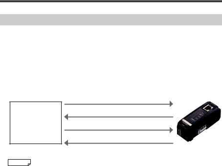
Specifying the IP address using the DCP protocol
In the PROFINET communication, you can specify the IP address of I/O devices using the DCP protocol (Discovery and Configuration Protocol).
The DCP protocol offers two methods for setting the IP address.
(1)The IP address can be set by the I/O controller based on the device name information of the I/O device.
(2)The IP address and device name of the I/O device can be set by the I/O supervisor (PC, etc.).
(1)Check the presence of an I/O device
(2)Response
PROFINET
communication (3) Set the IP address
I/O Controller
(4) Response
I/O device

 Reference If the IP address of the I/O device will be set by the I/O controller, the I/O device name must match the name in the config of the I/O controller.
2 |
- PROFINET Communication Unit DL-PN1 User's Manual (IB) - |
Communicating with the IB Series
Types and Number of Connectable Sensor Amplifiers
Name |
Amplifier form |
Main unit |
Expansion unit |
Maximum number of connectable units |
|
|
DIN rail mounting type |
IB-1000 |
IB-1050 |
4 |
|
|
(1 main unit, 3 expansion units) |
||||
IB Series |
|
|
|
||
|
|
|
|
||
Panel mounting type |
IB-1500 |
IB-1550 |
4 |
||
|
|||||
|
(1 main unit, 3 expansion units) |
||||
|
|
|
|
||
|
|
|
|
|
The DL-PN1 can connect to multiple sensor amplifiers (a single main unit and multiple expansion units) which support D-bus. "D-bus" is the name of KEYENCE's wiring-saving system for sensor amplifiers.
Different types of sensor amplifiers with D-bus support can be connected to a single DL-PN1 unit.
How many and what types of sensor amplifiers can be connected depends on the sensor amplifiers or units to be connected. Please inquire for details.
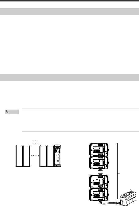
Assigning ID Numbers and Slot Numbers
Several sensor amplifiers can be connected to the DL-PN1. ID numbers and slot numbers for data identification are assigned to each sensor amplifier.
The method for assigning ID numbers and slot numbers is as follows:
•The numbers are assigned in order, starting from the sensor amplifier that is the main unit. (Optional numbers cannot be assigned.)
•00 is assigned as the ID number and slot number of the DL-PN1.
Point • You cannot change the ID numbers and slot numbers assigned to the sensor amplifiers.
•In this manual, ID number 00 to ID number 04 are denoted as ID00 to ID04, and slot number 00 to slot number 04 are denoted as Slot0 to Slot04 respectively.
For DIN rail mounting type |
|
For panel mounting type |
|
||||||
Slot number |
01 |
02 |
03 |
04 |
00 |
Slot number ID number Sensor amplifier |
|
||
ID number |
01 |
02 |
03 |
04 |
00 |
|
|
|
|
|
|
|
|
|
|
01 |
01 |
Main unit |
|
|
|
|
|
|
|
02 |
02 |
Expansion unit |
|
|
Main |
Expansion |
Expansion Expansion |
|
|
|
|
|
|
|
unit |
unit |
unit |
unit |
|
... |
... |
... |
|
|
|
|
|
|
|
Sensor amplifier |
|||
|
|
|
|
|
|
|
|
|
|
|
|
|
|
|
|
03 |
03 |
Expansion unit |
Slot number 00 |
|
|
|
|
|
|
|
|
|
|
|
|
|
|
|
|
|
|
|
ID number 00 |
|
|
|
|
|
|
04 |
04 |
Expansion unit |
|
- PROFINET Communication Unit DL-PN1 User's Manual (IB) - |
3 |
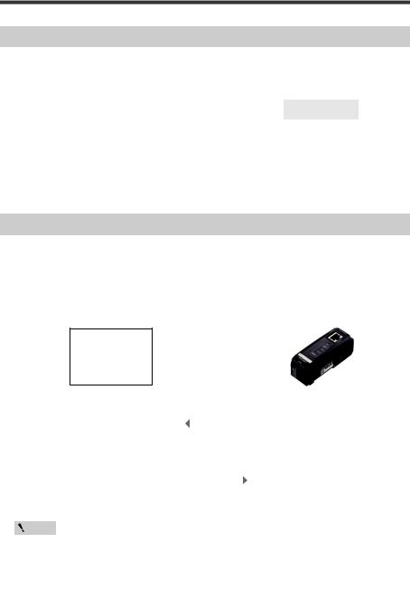
DL-PN1 PROFINET Communication Overview
The DL-PN1 enables you to read or write various settings and conditions of the sensor amplifier via PROFINET.
Examples are shown below.
Item |
Data I/O |
Record Data |
Reference |
|
Communication |
Communication |
page |
||
|
||||
Reading the sensor amplifier control output |
|
|
8 |
|
|
|
|
|
|
Executing the external input to the sensor amplifier |
|
|
8 |
|
|
|
|
|
|
Reading the sensor amplifier comparator value |
|
|
9 |
|
|
|
|
|
|
Changing the sensor amplifier setting value |
|
|
14 |
|
|
|
|
|
DL-PN1 PROFINET functions are specified in a GSDML file.
You can download the GSDML file from the KEYENCE website:
http://www.keyence.com
Data I/O Communication
What is data I/O communication?
This function enables cyclic (i.e. in fixed intervals) data communications with the PROFINET devices. This function provides high-speed control with several to several tens of milliseconds.
The communication can be controlled by referencing and updating the variables in the PLC, making it easy to control the programs on the PLC side.
PROFINET communication I/O Controller
Input Area |
|
|
|
|
|
Output Area |
|
|||||
|
|
|
|
|
|
|
|
|
|
|
|
|
|
· Status result |
|
|
|
|
|
|
|
· Status result |
|
|
|
|
· Control/status/error result |
|
|
|
|
|
|
|
· Control/status/error result |
|
|
|
|
· Read comparator value |
|
|
|
Update time |
|
· Read comparator value |
|
|
|||
|
|
|
|
(Communication |
|
|
|
|
||||
|
|
|
|
|
|
|
|
|||||
Output Area |
|
|
cycle) |
Input Area |
|
|||||||
|
|
|
|
|
|
|||||||
|
· Execute external input |
|
|
|
|
|
|
|
· Execute external input |
|
|
|
|
|
|
|
|
|
|
|
|||||
|
|
|
|
|
|
|
|
|
|
|
|
|
|
|
|
|
|
|
|
|
|
|
|
|
|
|
|
|
|
|
|
|
|
|
|
|
|
|
Point • Communication settings for the data I/O communication, such as Update time (communication cycle) and the data size, will be configured on the PLC side.
•In a network with many connected devices (including the PROFINET devices), a network delay and/or packet loss may occur when there is a heavy load on the network. Conduct a thorough verification before the operation.
4 |
- PROFINET Communication Unit DL-PN1 User's Manual (IB) - |

Data I/O communication device map (DL-PN1 PROFINET I/O controller)
DL-PN1 (Slot 0)
Input
Address |
Bit |
Function name |
|
Description |
Value |
|
0 |
Reserved for system |
- |
- |
|
|
1 |
Reserved for system |
- |
- |
|
|
|
|
|
|
0: Normal |
|
2 |
Comparator value property |
Stores the comparator value status. |
1: Disabled status |
|
|
|
|
|
|
“----”, “FFFF”, or “-FFFF” |
|
|
|
|
|
|
|
3 |
Reserved for system |
- |
- |
|
0 |
4 |
Reserved for system |
- |
- |
|
|
5 |
Reserved for system |
- |
- |
|
|
6 |
Warning |
One of the sensor amplifiers is in |
0: No warning |
|
|
warning state. |
1: Warning |
|||
|
|
|
|||
|
|
|
|
|
|
|
|
|
Stores the error status of the sensor |
|
|
|
7 |
Error status |
amplifiers. |
0: No error occurred. |
|
|
|
|
|
"Types of error and error code" |
1: Error occurred. |
|
|
|
(page 29) |
|
|
|
0 |
External input response 1 |
Stores the external input response |
0: No input |
|
|
to the sensor amplifier. |
1: Input reception |
|||
|
|
|
|||
|
|
|
|
|
|
|
1 |
External input response 2 |
Stores the external input response |
0: No input |
|
|
to the sensor amplifier. |
1: Input reception |
|||
|
|
|
|||
|
|
|
|
|
|
|
2 |
External input response 3 |
Stores the external input response |
0: No input |
|
|
to the sensor amplifier. |
1: Input reception |
|||
|
|
|
|||
1 |
|
|
|
|
|
3 |
External input response 4 |
Stores the external input response |
0: No input |
||
|
to the sensor amplifier. |
1: Input reception |
|||
|
|
|
|||
|
|
|
|
|
|
|
4 |
Reserved for system |
- |
- |
|
|
5 |
Reserved for system |
- |
- |
|
|
6 |
Reserved for system |
- |
- |
|
|
7 |
Reserved for system |
- |
- |
|
2 to 15 |
0 to 7 |
Reserved for system |
- |
- |
|
|
|
|
|
|
|
Sensor amplifier (Slot 1 to 4)
Input
Address |
Bit |
Function name |
Description |
Value |
|
|
0 |
High |
ON/OFF of the High state of the |
0: OFF |
|
|
sensor amplifiers is output. |
1: ON |
|||
|
|
|
|||
|
|
|
|
|
|
|
1 |
Low |
ON/OFF of the Low state of the |
0: OFF |
|
|
sensor amplifiers is output. |
1: ON |
|||
|
|
|
|||
|
|
|
|
|
|
|
2 |
Go |
ON/OFF of the Go state of the |
0: OFF |
|
|
sensor amplifiers is output. |
1: ON |
|||
16+7(a-1)* |
|
|
|||
|
|
|
|
||
3 |
Reserved for system |
- |
- |
||
|
|||||
|
4 |
Reserved for system |
- |
- |
|
|
5 |
Reserved for system |
- |
- |
|
|
6 |
Reserved for system |
- |
- |
|
|
7 |
Reserved for system |
- |
- |
|
|
|
|
|
|
- PROFINET Communication Unit DL-PN1 User's Manual (IB) - |
5 |
Address |
Bit |
Function name |
|
Description |
Value |
|
|
0 |
Reserved for system |
- |
- |
||
|
|
|
|
|
0: Normal |
|
|
1 |
Comparator value invalid |
Stores the comparator value status. |
1: Comparator value invalid |
||
|
|
|
|
|
“----” |
|
|
|
|
|
|
|
|
|
|
|
|
|
0: Normal |
|
|
2 |
Comparator value under range |
Stores the comparator value status. |
1: Comparator value under |
||
|
|
|
|
|
range “-FFFF” |
|
|
|
|
|
|
|
|
|
|
|
|
|
0: Normal |
|
|
3 |
Comparator value over range |
Stores the comparator value status. |
1: Comparator value over |
||
17+7(a-1)* |
|
|
|
|
range “FFFF” |
|
|
|
|
|
|
||
4 |
Reserved for system |
- |
- |
|||
|
||||||
|
5 |
Reserved for system |
- |
- |
||
|
|
|
Represents the warning status of the |
|
||
|
6 |
Warning |
sensor. |
0: No warning |
||
|
|
|
|
"Types of error and error code" |
1: Warning |
|
|
|
|
(page 29) |
|
||
|
|
|
Stores the error status of the sensor |
|
||
|
7 |
Error status |
amplifiers. |
0: No error occurred. |
||
|
|
|
|
"Types of error and error code" |
1: Error occurred. |
|
|
|
|
(page 29) |
|
||
|
0 |
External input response 1 |
Stores the external input response |
0: No input |
||
|
to the sensor amplifier. |
1: Input reception |
||||
|
|
|
||||
|
|
|
|
|
|
|
|
1 |
External input response 2 |
Stores the external input response |
0: No input |
||
|
to the sensor amplifier. |
1: Input reception |
||||
|
|
|
||||
|
|
|
|
|
|
|
|
2 |
External input response 3 |
Stores the external input response |
0: No input |
||
|
to the sensor amplifier. |
1: Input reception |
||||
|
|
|
||||
18+7(a-1)* |
|
|
|
|
|
|
3 |
External input response 4 |
Stores the external input response |
0: No input |
|||
|
to the sensor amplifier. |
1: Input reception |
||||
|
|
|
||||
|
|
|
|
|
|
|
|
4 |
Reserved for system |
- |
- |
||
|
5 |
Reserved for system |
- |
- |
||
|
6 |
Reserved for system |
- |
- |
||
|
7 |
Reserved for system |
- |
- |
||
19+7(a-1)* to |
0 to 7 |
Comparator value |
Used when reading the comparator |
INT32 |
||
22+7(a-1)* |
|
|
value (P.V. value). |
|
||
*"a" represents a Slot number. When Addresses were assigned in order, the Address for Slot 1 is 16, 17, 18, or 19 to 22.
Data I/O communication device map (PROFINET I/O controller DL-PN1)
DL-PN1 (Slot 0)
Output
|
Address |
Bit |
|
Function name |
Description |
Value |
|
|
0 |
|
External input request 1*1 |
Requests the external input to the |
0: OFF |
|
|
|
sensor amplifiers. |
1: ON |
||
|
|
|
|
|
|
|
|
|
1 |
|
External input request 2*1 |
Requests the external input to the |
0: OFF |
|
|
|
sensor amplifiers. |
1: ON |
||
|
|
|
|
|
|
|
|
|
2 |
|
External input request 3*1 |
Requests the external input to the |
0: OFF |
|
|
|
sensor amplifiers. |
1: ON |
||
|
0 |
|
|
|
|
|
|
3 |
|
External input request 4*1 |
Requests the external input to the |
0: OFF |
|
|
|
|
sensor amplifiers. |
1: ON |
||
|
|
|
|
|
|
|
|
|
4 |
|
Reserved for system |
- |
- |
|
|
5 |
|
Reserved for system |
- |
- |
|
|
6 |
|
Reserved for system |
- |
- |
|
|
7 |
|
Reserved for system |
- |
- |
6 |
|
|
- PROFINET Communication Unit DL-PN1 User's Manual (IB) - |
|||

*1 External input request to the sensor amplifiers connected to the DL-PN1 (Slot 0) can be executed en bloc. (Smart Access function)
Functions assigned to the external input request 1 to 4 are as follows:
•External input request 1: ZERO SHIFT input
•External input request 2: RESET input
•External input request 3: TIMING input
•External input request 4: Adjust input
Functions assigned to the external input request 1 to 4 can be changed. Refer to the IB series user's manual.
Sensor amplifier (Slot 1 to 4)
Output
Address |
Bit |
Function name |
Description |
Value |
|
0 |
External input request 1 |
Requests the external input to the |
0: OFF |
|
sensor amplifiers. |
1: ON |
||
|
|
|
||
|
|
|
|
|
|
1 |
External input request 2 |
Requests the external input to the |
0: OFF |
|
sensor amplifiers. |
1: ON |
||
|
|
|
||
|
|
|
|
|
|
2 |
External input request 3 |
Requests the external input to the |
0: OFF |
|
sensor amplifiers. |
1: ON |
||
|
|
|
||
1 to 4 |
|
|
|
|
3 |
External input request 4 |
Requests the external input to the |
0: OFF |
|
|
sensor amplifiers. |
1: ON |
||
|
|
|
||
|
|
|
|
|
|
4 |
Reserved for system |
- |
- |
|
5 |
Reserved for system |
- |
- |
|
6 |
Reserved for system |
- |
- |
|
7 |
Reserved for system |
- |
- |
|
|
|
|
|
Functions assigned to the external input request 1 to 4 are as follows:
•External input request 1: ZERO SHIFT input
•External input request 2: RESET input
•External input request 3: TIMING input
•External input request 4: Adjust input
Functions assigned to the external input request 1 to 4 can be changed. Refer to the IB series user's manual.
Communication Methods
The following describes how the I/O controller communicates with the DL-PN1 (data I/O communication).
• "Reading an output from a sensor amplifier" (page 8)
• "Entering an external input to a sensor amplifier" (page 8)
• "Reading comparator values (P.V. values) from sensor amplifiers" (page 9)
- PROFINET Communication Unit DL-PN1 User's Manual (IB) - |
7 |

Reading an output from a sensor amplifier
Available outputs: High, Low, Go
This example shows how to read the High output from Slot 1 (ID01).
Master
1
Slot 1
0
Bit 0 of the input address 16
Sensor amplifier |
(1) |
|
|
|
Output |
ON |
|
|
|
OFF |
|
|
|
|
High output of ID01 |
|
|
|
|
|
|
|
|
|
(1)The output from the sensor amplifier entered into Bit 0 of the input address 16 via data I/O communication.
This example shows how to read the High output from the sensor amplifier ID01.
Entering an external input to a sensor amplifier
Available external inputs: PRESET, TIMING, RESET, error clear This example shows how to enter the TIMING input from Slot 1 (ID01).
Master |
|
(1) |
|
|
|
|
External input request |
1 |
|
|
|
|
0 |
|
|
|
|
|
Slot 1 |
|
|
|
|
|
|
|
|
|
|
Bit 1 of the output address 1 |
(2) |
|
|
|
||
External input response |
1 |
|
|
|
|
|
|
|
|
|
|
||
0 |
|
|
|
|
|
|
Slot 1 |
|
|
|
|
|
|
|
|
|
|
|
|
|
Bit 1 of the input address 18 |
|
|
|
|
|
|
Sensor amplifier |
ON |
|
|
|
|
|
External input |
OFF |
|
|
|
|
|
TIMING input of ID01 |
|
|
|
|
|
|
|
|
|
|
|
|
|
(1)The output address value to which an external input request was assigned is linked via data I/O communication and the external input of the sensor amplifier is turned on or off.
(2)You can check the input status of the sensor amplifier with the external input response.
8 |
- PROFINET Communication Unit DL-PN1 User's Manual (IB) - |

Reading comparator values (P.V. values) from sensor amplifiers
Master
Comparator value invalid Input address 17/24/31 Bit 1 of Slot 1/2/3
Comparator value over range Input address 17/24/31 Bit 2 of Slot 1/2/3
Comparator value under range Input address 17/24/31 Bit 3 of Slot 1/2/3
Comparator value of ID 01 Input address 19 to 22 (DEX) of Slot 1
Comparator value of ID 02 Input address 26 to 29 (DEX) of Slot 2
Comparator value of ID 03 Input address 33 to 36 (DEX) of Slot 3
Sensor amplifier
Comparator value of ID 01
Comparator value of ID 02
Comparator value of ID 03
1 |
(2) |
|
|
||
0 |
(2) |
|
1 |
||
|
||
0 |
(2) |
|
1 |
||
|
||
0 |
|
1234 |
4567 |
|
6789 |
2345 |
|
5678 |
7890 |
3456 |
|
|
8901 |
(1)
1234 |
4567 |
|
6789 |
2345 |
|
5678 |
7890 |
3456 |
|
|
8901 |
This example shows how to read the comparator values (P.V.values) from the sensor amplifiers ID01, ID02, and ID03.
(1)When the comparator value of a sensor amplifier is updated, the value of the input address is also updated via data I/O communication.
If the judgment value is correct, the parameter range is
-from - 999.99 to +999.99 (percent mode).
-from - 99.999 to +99.999 (size mode).
If the comparator value is over range, under range, or invalid, the previous value is retained without updating the comparator value. To confirm whether the current value is correct, use the comparator value property.
(2)The comparator value invalid, comparator value over range, or comparator value under range is entered.
If the comparator value of a sensor amplifier is "invalid", "over", or "under", the bit corresponding to the ID number of that sensor amplifier flips to 1.
- PROFINET Communication Unit DL-PN1 User's Manual (IB) - |
9 |
Loading...