


CZ-K1P
Table of contents
 Loading...
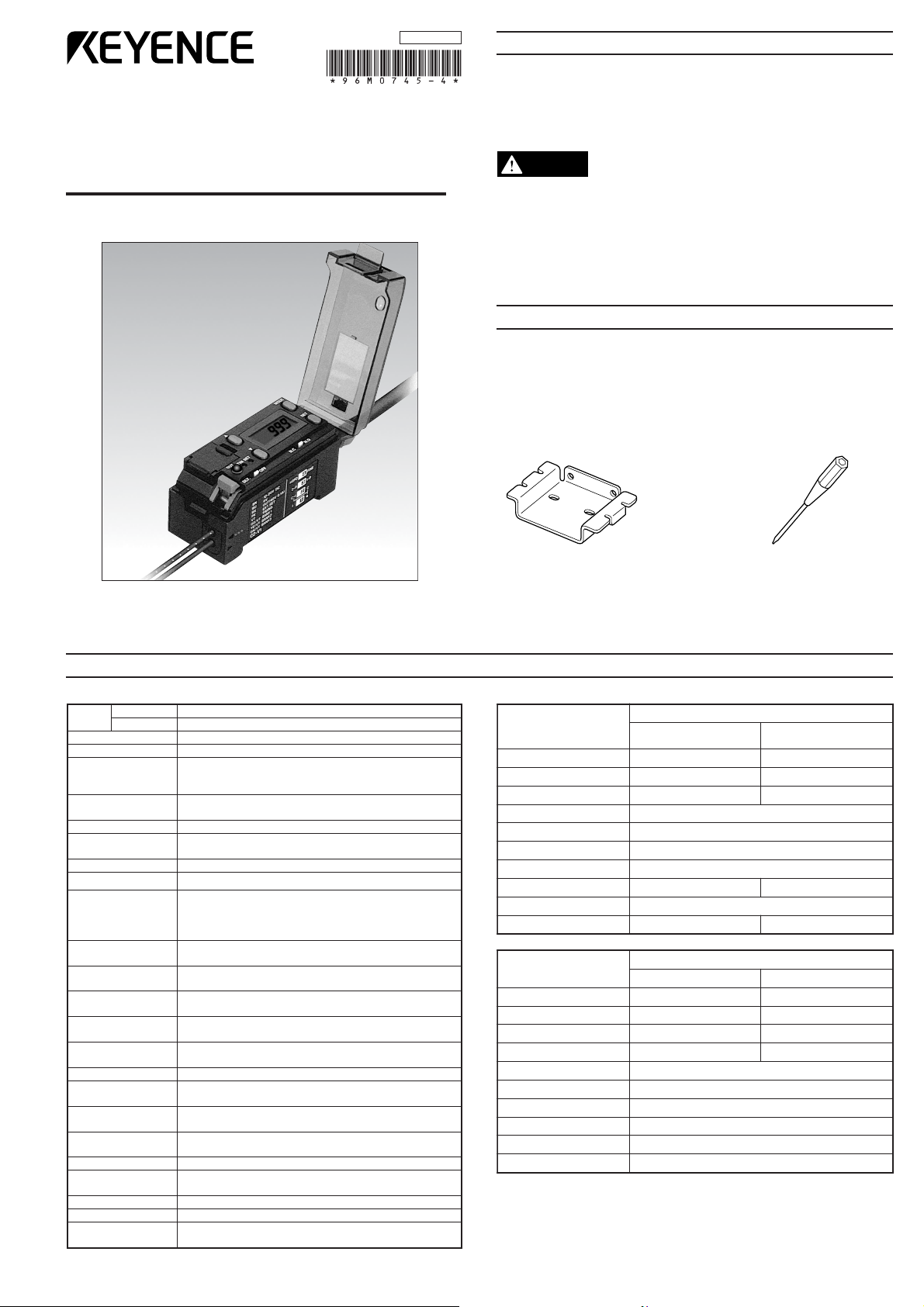
WARNING
ledoM
tuptuoNPN1K-ZC
tuptuoPNPP1K-ZC
ecruosthgiL DELeulB,DELneerG,DELdeR
emitesnopseR 003 μ )elbatceleshctiws(s
m1/s
srotacidnI
,DELegnarO:noitarbilaC,DELdeR:tuptuO
,DELneerG:tupninoitazinorhcnyslanretxE
)neerG/deR(DC
L:ytisnetnithgildeviecer/etargnihctaM
noitacidnirorrE
,ytisnetnithgiltneiciffusni,ytisnetnithgilssecxE
e
cnereffidroloctneiciffusni
dohtemnoitarbilaC )elbatceleshctiws(noitarbilactniop-2/tniop-1
eulavecnareloT
tnemtsujda
yalpsidlatigidnognitteseulavlaciremuN
edomnoitaitnereffiD )elbatceleshctiws(edomI/edomI+C/edo
mC
noitcnufremiT )elbatceleshctiws()sm04(remityaled-FFO/FFOremiT
edomtuptuO
noitceles
roloctegratnehwnosnr
uT:tuptuohctaM
.rolocderetsigersehctam
tnereffidsiroloctegratnehwnosnruT:tuptuohctamsiM
)elbatceleshctiw
s(.rolocderetsigermorf
-orhcnyslanretxE
tupninoitazin
005:deepsesnopseR μ .xams
noitarbilaclanretxE
tupni
.ni
msm02:emitesnopsertupnI
rolocderetsigeR
noitceles
,)tupnilanretxeyB(noitcelesknab-8
.nimsm02:emitesnopser
tupnI
tuptuolortnoC
.xamCDV04:rotcelloc-nepoPNProNPN
.xamV0.1:egatlovlaudiseR,).xamAm001(
tiucricnoitceto
rP
tnerrucrevo,)ylppusrewop(noitcetorpytiralop-esreveR
)tuptuo(rebrosbaegrus,)tuptuo(noitcetorp
ylppusre
woP CDV42ot21 ± .xam%01:)P-P(elppiR,%01
tnerruC
noitpmusnoc
.xamAm57
thgiltneibmA
,.xamxul000,5:pmaltnecsedna
cnI
.xamxul000,01:thgilnuS
tneibmA
erutarepmet
.1
55+ot01- ° 131ot41(C ° noitasnednocoN,)F
ytidimuhevitaleR noitasnednocoN,%58ot53
noitarbiV
Zdna,Y,Xniedutilpm
aelbuodmm5.1,zH55ot01
ylevitcepsersruoh2,snoitcerid
kcohS s/m005
2
ylevitcepsersemit3,snoitceridZdna,Y,Xni
lairetamgnisuoH etanobracyloP
gnidulcni(thgieW
)elbacm2
g511.xorpp
A
epyT
evitcelfeR
ecnatsidgnitcetedgnoLtopsmaebllamS
ledoM04-ZC14-ZC
egnarnoitceteD 07 ± mm0261 ± mm4
retemaidtopstse
llamS .aidmm6.aidmm1
suidardnebmuminiM mm52Rmm51R
gnitarerusolcnE 76PI
erutarepmettneibmA 07+ot04- ° 851+ot04-(C
° noitasnednocoN,)F
ytidimuhevitaleR noitasnednocoN,%58ot53
htgnelrebiF )tuc-eerf(m2
lairetamgnisuoH etalyra
yloP
thgieW g72.xorppA
epyT
evitcelfeR
elbatsujdaezisllamS
tops
weiv-edis,ezisllamS
topselbatsujda
ledoM01-ZC11-ZC
egnarnoitceteD mm03
ot01mm51ot3
retemaidtopstsellamS .aidmm5.3ot9.0.aidmm5.1ot9.0
suidardnebmuminiM mm52R
gnitarerusolcnE 04PI
eru
tarepmettneibmA 07+ot04- ° 851+ot04-(C ° noitasnednocoN,)F
ytidimuhevitaleR noitasnednocoN,%58ot53
htgnelrebi
F )tuc-eerf(m2)tuc-eerf(m1
lairetamgnisuoH leetssselniatS:esacrebiF,munimulA:esacsneL
thgieW g5.xorppAg31.xo
rppA
96M0745
RGB Digital Fiberoptic Sensor
SAFETY PRECAUTIONS
This manual describes the instructions, operating procedures and
precautions for using the CZ-K1(P) Series.
Before beginning operation, please read this manual carefully to get the
most from your CZ-K1(P) Series.
Keep this manual handy for future reference.
CZ-K1(P) Series
Instruction Manual
• The CZ-K1(P) Series is intended for the detection of target
objects. Do not use the CZ-K1(P) Series in a safety circuit to
protect the human body.
• The CZ-K1(P) Series does not have an explosion-proof structure.
Do not use it in a location where any flammable gases, liquid or
powder exist.
ACCESSORIES
Instruction manual (This manual): 1
Mounting bracket: 1 Resin driver: 1
SPECIFICATIONS
Amplifier Fiber unit
1. When several units are connected, the acceptable ambient temperature varies
depending on the conditions given below. To connect several units, be sure to
mount them to a DIN rail (metallic plate). Ensure that the output current is 20
mA max.
• When 3 to 10 units are connected: -10 to +50°C (14 to 122°F)
• When 11 to 16 units are connected: -10 to +45°C (14 to 113°F)
1

CONNECTING FIBER UNIT AND AMPLIFIER
2
1
3
12 to 24
VDC
Load
5 to 40
VDC
0 V
100 mA max.
Photoelectric sensor
main circuit
Overcurrent
protection
Brown
Black
Blue
12 to 24 VDC
External synchronization
input
External bank selection 1
External bank selection 2
External bank selection 3
External calibration
0 V
Brown
Black
Load
Pink
Purple
Orange/purple
Yellow/purple
Green/purple
Blue
100 mA max.
0 V
12 to 24
VDC
Pink
Purple
Orange/purple
Yellow/purple
Green/purple
Blue
Photoelectric sensor
main circuit
Short-circuit current: Approx. 1 mA
PLC, etc.
1. Tilt the quick-release lever.
2. Push the single-core fiber to the transmitter side, and the multiplecore fiber to the receiver side as far as they will go (Approx. 14 mm of
the fiber will be inserted.).
* Inserting the fiber in the wrong side will decrease the original
detection performance. Be sure to check the markings on the
amplifier’s lateral side before inserting the fiber.
3. Raise the quick-release lever.
■ Detaching expansion units from DIN rail
1. Detach the end units.
2. Slide the expansion unit that is to be detached. Detach it individually
from the DIN rail.
Note 1: When connecting several amplifiers, be sure to use a DIN rail
and the end units.
Note 2: Be sure to turn the power off before connecting/disconnecting
amplifiers.
Note 3: Do not remove the protective cover on the expansion connector
from the outermost unit.
Note 4: Do not detach several units from the DIN rail while they are
connected to each other.
Note 5: When several units are connected, confirm that the ambient
temperature is appropriate. (See “Specifications” on page 1.)
Quick-release lever
Transmitter side
(with markings)
Single-core fiber
Receiver side
(with markings)
Multiple-core fiber
Single-core
(Transmitter side)
Multiple-core
(Receiver side)
MOUNTING AMPLIFIER
■ Mounting/detaching amplifier to/from DIN rail or
mounting bracket
Hook the claw on the rear side of the amplifier onto the DIN rail or the
mounting bracket, and then hook the front side claw to the rail or
bracket while pressing the amplifier forward. To detach the amplifier,
unhook the front claw by lifting the amplifier front side while pressing it
forward.
Mounting
Detaching
■ Side mounting
Using the side holes of the supplied
mounting bracket, secure the amplifier
with the screws.
CONNECTING SEVERAL AMPLIFIERS
■ Mounting expansion units
Up to 16 expansion units (FS-T2, FS-M2, FS-V12, PS-T2) can be
mounted to the side of the CZ-K1(P) amplifier.
1. Remove the protective cover on the
side of the amplifier.
2. Mount expansion units to the DIN rail
one at a time.
3. Slide one expansion unit toward the main unit or another unit. Align
the front claws of the units and push them together until you hear a
click.
4. Secure the units together by pushing the end units (included in the
expansion unit) from both sides.
Align the claw.
End unit (included with
Main unit
Expansion
units
the expansion unit)
Remove the
protective cover.
MOUNTING FIBER UNIT
• Use the supplied special mounting bracket to mount the fiber unit in
the desired position according to the location.
• Be sure to limit the tightening torque to 0.3 Nm or less.
Mounting example 1 Mounting example 2
Reference: To cut the fiber to the desired length, use the special cutter
included with the fiber unit.
INPUT/OUTPUT CIRCUIT
Connections
NPN
Brown
Black
Pink
Purple
Orange/purple
Yellow/purple
Green/purple
Blue
100 mA max.
Load
12 to 24 VDC
5 to 40 VDC
External calibration
External synchronization
input
External bank selection 1
External bank selection 2
External bank selection 3
0 V
Output circuit
NPN
Input circuit
NPN
External calibration input
External synchronization input
External bank selection input 1 to 3
PNP
PNP
Photoelectric sensor
main circuit
Overcurrent
protection
Brown
100 mA max.
Black
Blue
Load
12 to 24
VDC
0 V
PNP
External calibration input
External synchronization input
External bank selection input 1 to 3
The sticker on the right is included with the
expansion unit. Attach the sticker close to the
sensor units.
Up to 16 expansion units can be connected.
+5 V
+5 V
main circuit
Photoelectric sensor
Short-circuit current: Approx. 1 mA
2
Pink
Purple
Orange/purple
Yellow/purple
Green/purple
PLC, etc.
Blue
0 V
PART NAMES
1234
MODE
SET
N.O
N.C
OFF
DLY.
OUT
TIM
SET
HSPD
FINE
2-P
1-P
C+I C
I
1234
MODE
SET
N.O
N.C
OFF
DLY.
OUT
TIM
SET
edoMhctiwSnoitpircseD
)roloC(C
stnenopmocrolocgnisurolocstceteD
.)Bdna,G,R(
I+C
dnaroloC(
)ytisnetni
stnenopmocrolocgnisurolocstceteD
thgi
ldeviecerdna)Bdna,G,R(
.)ytitnauqthgildeviecer(ytisnetni
I
)ytisnetnI(
thgildeviecergnisurolocstceteD
.)yt
itnauqthgildeviecer(ytisnetni
edoMhctiwSnoitpircseD
P-1
tniop-1(
)noitarbilac
ehT(.rolocdeificepsenostceteD
tcetedottesyllacitamotuasiytivitisnes
gniruddetcelesrolocenoehtylno
).noit
arbilac
P-2
tniop-2(
)noitarbilac
.srolocdeificepsowtsetaitnereffiD
ottesyllacitamotuasiytivitisnesehT(
eht
etaitnereffidoteulavlamitpoeht
).noitarbilacgniruddetcelessrolocowt
edoMhctiwSnoitpircseD
ENIF
)niaF(
hgihhtiwsrolocsetaitnereffiD
.noisicerp
DPSH
)deeps-hgiH(
deeps-hgihahtiwsrolocsetaitnereffiD
003foesnopse
r μ .s
edoMhctiwSnoitpircseD
.O.N
hctamroloC(
)tuptuo
tegratehtnehwnodenrutsituptuO
.rolocderetsigerehtsehctamroloc
.C.N
roloC(
hctamsim
)tuptuo
tegratehtnehwnod
enrutsituptuO
deretsigerehthctamtonseodroloc
.roloc
edoMhctiwSnoitpircseD
FFOremiT .yaledynatuohtiwnodenrutsituptuO
sm04
yaled-FFO
.sm04rofdeyaledsituptuO
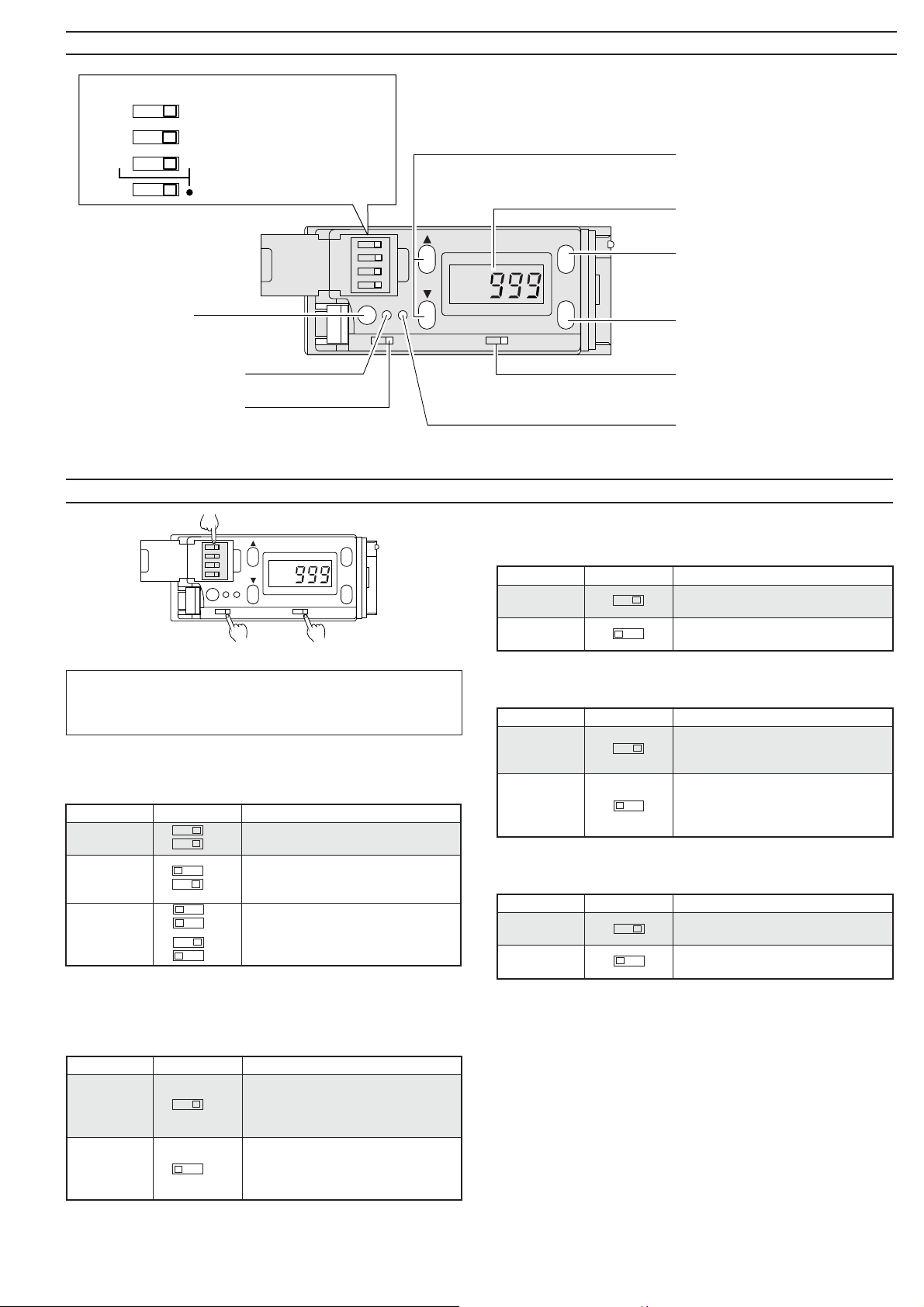
DIP switches for mode setting
Output indicator
High-speed/High-precision
2-point/1-point calibration
Differentiation mode
selection
UP/DOWN key
• Changes sensitivity setting value.
• Changes channels.
LCD display monitor
MODE selection button
• Changes display.
• Shows matching rate.
• Shows setting value.
SET button
Sets sensitivity.
External synchronization
input indicator
Timer selection switch
Switches between Timer
OFF and 40 ms OFF-delay.
SETTING EACH MODE
DIP switch
Timer selection switch
Factory setting
“❋” indicates the factory-set mode. Normally, you should use the
CZ-K1(P) with the setting indicated by “❋”, and only change the
setting if required.
■ Differentiation mode setting (Using DIP switches 1 and 2)
Change the setting according to the detection conditions such as the
target color or received light intensity.
❋
or
Sensitivity setting in C or C + I mode ➞ Go to page 4.
Sensitivity setting in I mode ➞ Go to page 5.
2
1
2
1
2
1
2
1
Output selection switch
Output selection switch
Switches between N.O. and N.C.
Calibration indicator
■ FINE/HSPD selection (Using DIP switch 4)
Use HSPD when the detection requires a response speed less than 1
ms.
❋
4
4
■ N.O./N.C. selection
Change the setting to invert the output mode.
❋
N.C.
N.C.
N.O.
N.O.
■ Timer OFF/40 ms OFF-delay selection
Change the setting to delay the output timing.
❋
DLY.
DLY. OFF
OFF
❋
■ 1-point/2-point calibration selection1. (Using DIP switch 3)
Change the calibration method.
3
1. The setting of DIP switch 3 is effective only in the C and C + I modes.
The setting is unnecessary in I mode.
3
3
Loading...