


 Loading...
96M10103
High-performance Micro Static Eliminatior
SJ-M

Instruction Manual
Before using this Compact Static Eliminator, be sure to thoroughly read this Instruction Manual.
After you are finished with this Instruction Manual, be sure to store it in a safe place for quick reference.
1
Preface
This document describes handling, method of operation and precautions when using the Compact Spot-type Static Eliminator SJ-M 300 Series. Before you start to use the SJ-M 300 Series, be sure to thoroughly read this document in order to make full use and safely use its functions.
Store this document in a safe place so that you can retrieve it whenever necessary.
■ Symbols
This manual uses the following symbols to alert you to important information.
Be sure to read this information.
 DANGER Failure to follow these instructions may lead to death or serious injury.
 WARNING Failure to follow these instructions may lead to injury.
 CAUTION Failure to follow these instructions may lead to product damage (product malfunction, etc.).
Important
Provides additional information on precautions and restrictions that must be followed in operation.
Note
Provides additional information on proper operation.
Tip Indicates useful information or information that aids understanding of text descriptions.
Indicates a reference item or page to be referred to in this manual or a separate manual.
Safety Precautions
■ General Precautions
 CAUTION • At startup and during operation, be sure to monitor the functions and performance of the SJ-M Series.
•We recommend that you take substantial safety measures to avoid any damage in the event that a problem occurs.
•Do not modify the SJ-M Series or use it in any way other than described in the specifications. The functions and performance of products used or modified in this way cannot be assured.
•When the SJ-M Series is used in combination with other instruments, functions and performance may be degraded, depending on operating conditions and the surrounding environment. Use the SJ-M after fully studying the effect of combined use with other instruments.
•Do not use the SJ-M Series for the purpose of protecting the human body.
■SJ-M Series Handling Precautions
The SJ-M Series is a high-voltage product that is not designed in an explosion-proof structure. Pay attention to the following when using the SJ-M Series.
 WARNING • To prevent electric shock and to ensure accurate static elimination, be sure to connect a Class D earth (maximum resistance of 100 Ohms).
•The power cable supplied with the exclusive power supply (SJ-U2) is a 125 V rated power cable. When connecting a power supply that exceeds this power rating to the SJ-M Series, the user must prepare a power cable having adequate voltage rating. If a power cable that does not meet the voltage rating is used, this may cause electric shock, fire or malfunction.
•Do not use this product in locations where there is the risk of ignition or explosion from flammable solvents or dirt and dust.
•High voltage is applied to this product. Prevent it from being splashed with water, oil, or flammable solvents. Failure to do so may cause insulation breakdown, which will result in electric shock or malfunction.
•Do not bring your fingers, tools, wire or other metallic objects near this product. Doing so may cause electric shock or malfunction.
•Protect the area around the tip of the Static Elimination Head with silicon, fluoro-resin or other highly ozone-resistant resin. Ozone that is generated may cause the metal or resin on the SJ-M Series to rust, corrode or deteriorate.
The ozone generated from this product may adversely affect the human body. For this reason, do not use the SJ-M Series in closed spaces. Be sure to use the SJ-M Series in a well-ventilated location. Also, do not bring your face close to the Static Elimination Head. The ozone generated from this product might be painful to your nose or throat.
•Do not use this product in locations where sudden changes in temperature or condensation are likely to occur.
•Do not operate this product with wet hands. Doing so may cause electric shock.
•Before starting inspection or maintenance, be sure to turn the power OFF. Failure to do so might result in electric shock or malfunction.
•During maintenance, do not directly touch the electrode probe. Doing so may cause personal injury.
•If any malfunction is observed in this product, immediately turn it OFF, and contact your nearest agent. You should never repair this product yourself. Doing so may cause electric shock or malfunction.
 CAUTION • Do not touch the electrode probe with a tool or other hard object. Damage to the electrode probe will prevent static elimination performance from being fully demonstrated, and cause accidents or malfunction.
•When this product is used for a long period of time, the electrode probe become dirty due to the adhesion of dust and dirt. If the ion level alarm indicator or condition alarm indicator lights, clean the electrode probe. If the product is used with the electrode probe in a dirty or dusty state, the static elimination performance can no longer be fully demonstrated, resulting in accidents or malfunction. We recommend periodically cleaning the electrode probe (as a guideline, once every two weeks in a regular operating environment though this depends on the installation conditions).
•Do not drop or subject this product to shock. Doing so might result in accident or malfunction.
•Use this product for static elimination only. Do not use it for other purposes.
•When installing the SJ-M Series, observe the minimum bending radius of all provided cables. Also, do not install the SJ-M with the cables deformed by staples or other objects. Doing so might cause the SJ-M to malfunction.
■Power Supply Precautions
 CAUTION • Use a DC power supply with rated 24 V output.
•Noise applied to the power supply may cause this product to malfunction. If this happens, install an insulated transformer.
•When using a switching regulator, be sure to connect a Class D earth to the Frame Ground terminal.
■Grounding Precautions
 CAUTION • To ensure safety and appropriate static elimination, be sure to ground this product.
•Be sure to connect a Class D earth (maximum resistance of 100 Ohms)
■Air Purge Function Precautions
 CAUTION • Be sure to use air of pressure to 0.2 MPa. Use outside of the rated air pressure range might result in accidents or malfunction.
•Be sure to supply clean or dry air of temperature –20°C or more through a filter of mesh size about 0.01μm. Moisture or oil contained in the air or nitrogen may cause discharge inside the Static Elimination Head, which may result in accidents or malfunction.
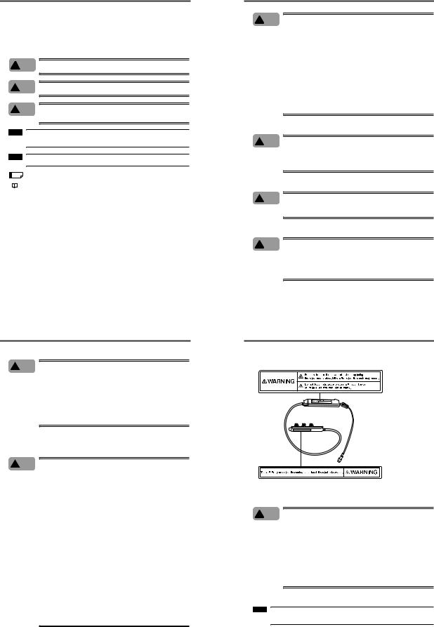
■ SJ-M Series Warning label
A WARNING label is affixed on the SJ-M Series to ensure safety. Read the description on this WARNING label to ensure correct use of the SJ-M Series.
WARNING labels in Japanese, German, French, Italian and Chinese (Simplified) are provided. Use them as necessary.
■ Installation Precautions
 CAUTION Avoid installing the SJ-M Series in the following locations as this may cause accidents.
•Locations directly subject to vibration and shock
•Locations subject to ambient temperature outside of the 0°C to +40°C range
•Locations subject to ambient humidity outside of the 35 to 65%RH range (condensation not allowed)
•Locations subject to sudden changes in temperature
•Locations subject directly to blasts from air conditioners
•Locations subject to volatile or flammable substance, solvents or corrosive gases
•Locations subject to large amounts of dirt, and dust, salt, iron and oil smoke
•Locations that may be splashed with water, oil or chemical mist
•Locations where strong magnetic and electrical fields are generated
■About Warm-up
Note
After turning the SJ-M Series ON, leave it for about 20 minutes to allow the ion balance to stabilize.
1
■ Other Precautions
 CAUTION • Be sure to read the WARNINGS and CAUTIONS described in each of the items in this Instruction Manual.
•This Static Eliminator has a built-in EEPROM. Do not turn the Static Eliminator OFF during the setup.
 CAUTION Refer to the following illustration to install the SJ-M300.
●Provide enough space between the static elimination bar and surrounding
walls as shown in the figures below. |
|
||
30mm |
30mm |
20mm |
20mm |
min. |
min. |
min. |
min. |
|
|
|
20mm min. |
●If a number of SJ-M300 units are used in combination, make a proper distance between adjacent static elimination bars.
300mm
min.
100mm
min.
Side-to-side installation |
Face-to-face installation |
•Do not install the Static Elimination Head at locations where moving parts of other equipment and machinery may place stress on the cable.
Precautions on Regulations and Standards
■ CE Marking
Keyence Corporation has confirmed that this product complies with the essential requirements of the applicable EC Directive, based on the following specifications.
Be sure to consider the following specifications when using this product in the Member State of European Union.
● |
EMC Directive (2004/108/EC) |
|
• |
Applicable standard |
EMI: 61326-1(evaluated according to EN55011 Group 1, Class A) |
|
|
EMS: 61326-1 |
•Be sure to provide a ground when installing the SJ-M Series.
•The length of cable (power lead and I/O leads) must be less than or equal to 30 m.
Remarks:
These specifications do not give any guarantee that the end-product with this product incorporated complies with the essential requirements of EMC Directive. The manufacturer of the end-product is solely responsible for the compliance on the end-product itself according to EMC Directive.
●Low-Voltage Directive (2006/95/EC)
•Applicable Standard : EN61010-1
•Overvoltage category I
•Use this product under pollution degree 2.
•Use the power supply for the SJ-M Series, that satisfies the requirements of the Limited Power Source specifications stipulated in EN60950-1 and certified by European third-party certification organization, or a Keyence Corporation AC adapter (SJ-U2). The specifications of the AC adapter (SJ-U2) are as follows.
When connecting to an SJ-U2, be sure to use a power cable compliant with European standards. Applicable standard: EN60950-1
Overvoltage category II Pollution degree 2
•Be sure to provide a ground when installing the SJ-M Series.
1-1 Features of the SJ-M Series
This section describes an outline of the functions, the features of the SJ-M Series.
Outline of the SJ-M Series
■ Pulse AC method
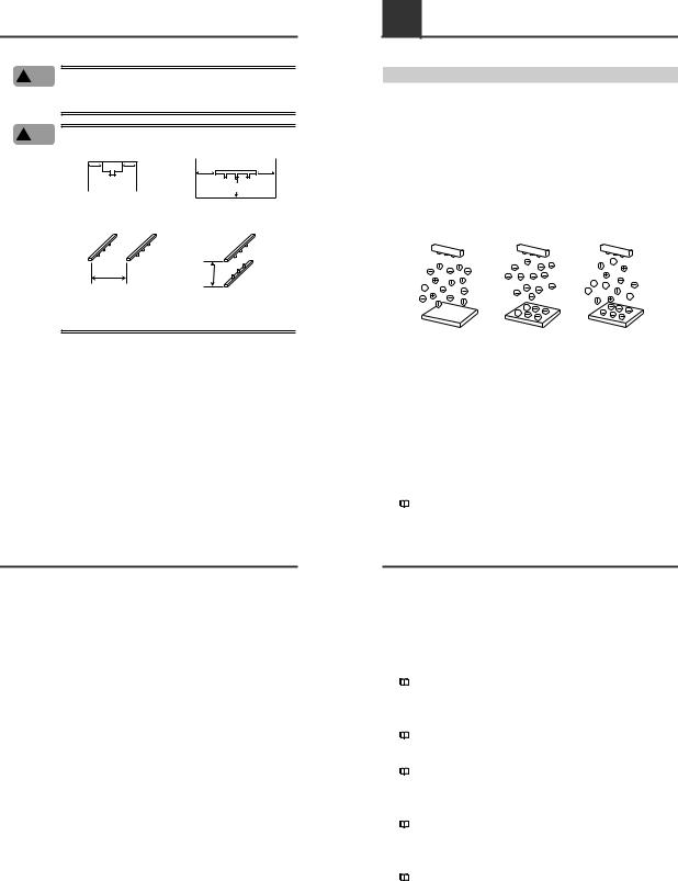
The SJ-M Series uses a pulse AC method that generates + and – charged air ions from a single electrode probe. This system ensures a maximum ion level per unit time, which in turn high-speed static elimination. The SJ-M Series also automatically controls the level of + and – ions generated matched to the charged state of the target object. This enables high-speed and high-precision static elimination suited to installation conditions.
■ I.C.C. (Ion Current Control) method
This control method calculates the charged level of the target object by sensing the state of ion current that arises due to the potential difference between the electrode on the Static Elimination Head and GND. Optimum static elimination matched to the state of the target object can be performed by rapidly supplying the optimum ions suited to the polarity and charged level of the target object.
Target without |
Eliminates electricity |
Eliminates electricity |
|
from positively |
from negatively |
||
static charge |
|||
charged target |
charged target |
||
|
Target: 0V |
Target: Positively charged |
Target: Negatively charged |
■ Versatile frequency settings
A variety of frequencies can be set for the SJ-R. This allows optimal static elimination according to the distance and the strength of the electric charge of the target.
■ Ion monitor functions
● Charge monitor
The integrated ion monitor allows you to learn how much the target object is charged by + or – ions. This monitor also allows you to confirm at a glance how static elimination is being performed.
● Ion level monitor
The ion level currently being generated by the Static Elimination Head is monitored at all times so that drops in the generated ion level can be diagnosed on the unit. The generated ion level is indicated by LEDs and an alarm can be output when the generated ions fall below a certain level. This allows you to monitor the influence of a dirty electrode probe in advance.
"Ion Monitor Functions" (page 8)
1-1 Features of the SJ-M Series
■ Alarm output functions
● Alarm output functions
An indicator blinks and an alarm signal is output, for example, when internal circuits are damaged or abnormal discharging occurs. When an alarm signal is output, generation of ions is forcibly stopped.
● Ion level alarm output function
An indicator lights and an alarm signal is output when the level of generated ions drops due to a dirty electrode probe, for example.
● Condition alarm output function
An indicator lights and an alarm signal is output when static elimination performance is impaired.
"Alarm Output Functions" (page 8)
■ Abnormal discharge detection function
Abnormal discharge caused by condensation on the electrode probe tip or adhesion of debris is detected. When abnormal discharge is detected, ion generation is forcibly stopped to prevent trouble at an early stage.
"Abnormal Discharge Detection Function" (page 8)
■ Ion balance adjustment function
The ion balance zero point can be fine-adjusted.
"Ion Balance Adjustment Function" (page 7)
■ Static elimination stop function
Static elimination only can be turned ON/OFF with the device still powered. This is achieved by shorting the 0V terminal with the static elimination stop input terminal on the Controller Unit (I/O terminal section) or by holding down the two ion balance adjustment keys simultaneously for about one second.
"Static Elimination Stop Function" (page 8)
■ Air purge function
Dirt can be prevented from sticking to the electrode probe on the SJ-M030 by attaching a joint to the air duct of the Static Elimination Bar and supplying clean dry air from the air compressor. This also extends the static elimination range.
"Air Purge Function" (page 9)
2
1-2 Checking the Contents of the Package
The package contains the following components and accessories. Before you start using the SJ-M Series, make sure that the package contains everything that it is supposed to contain. A Replacement Electrode Unit and other accessories are available as options.
"Appendices - List of Options" (page 13)
Package Contents
Static Elimination Bar
SJ-M030/070 Series |
Mounting Fixture |
|
1set |
WARNING labels (Japanese, German, French, Italian and Chinese (Simplified)) *
* Use as necessary.
Earth lead
Controller Unit (SJ-M300)
Instruction Manual
SJ-M
SJ-M Series
Flat-blade screwdriver
Options
AC Adapter SJ-U2 |
Tungsten electrode probe for SJ-M030/070 (set of 4 pieces) |
OP-42213 |
|
Silicon electrode probe for SJ-M030/070C (set of 4 pieces) |
OP-42214 |
|
Tungsten electrode probe for SJ-M030/070G (set of 4 pieces) OP-51644 |
|
|
Tungsten electrode probe for SJ-M030/070V (set of 4 pieces) OP-75352 |
|
|
Silicon electrode probe for SJ-M030/070VC (set of 4 pieces) |
OP-75353 |
*For details of the AC cable, contact the KEYENCE sales office in your district.
Extension cable SJ-C3
(3m cable, can be extended to 9m)
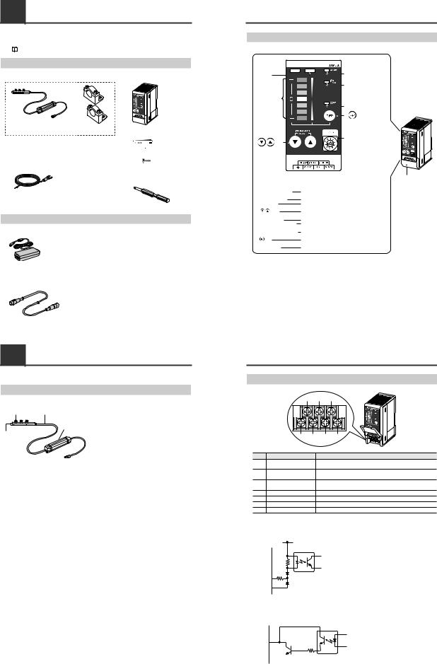
1-3 Names and Functions of Parts
This section describes the names and functions of parts on the SJ-M Series.
Static Elimination Bar
● SJ-M030/070 Series
(1) |
(3) |
(1) |
Electrode probe |
|
|
|
Ion charge is emitted from the tip of this probe. |
|
|
(2) |
Air duct |
(4)Supplies clean dry air.
(2) |
(3) |
High-voltage cable |
|
|
Ambient operating temperature: 0 to +40°C |
|
|
Minimum bending radius 30 mm |
|
(4) |
Drive unit |
|
|
Manages body information of the Static |
|
|
Elimination Bar or drives the Bar. |
1-3 Names and Functions of Parts
Controller Unit (operation/display section)
(1) Ion balance 


 indicator


(2) Ion level |
(5) Alarm indicator |
||
|
|
||
indicator |
|
|
|
|
|
(6) Ion level alarm indicator |
|
(3) Ion monitor |
|
|
|
|
|
(7) Condition alarm indicator |
|
|
|
(8) |
key |
|
|
(9) Rotary switch |
|
(4) |
keys |
|
|
|
|
|
FREQ |
|
Enlarged view of display section |
Terminal plate cover |
|
|
|
|
|
(1) Ion balance indicator |
Lights when the charged level of the target object is |
||
|
|
displayed. |
|
(2) Ion level indicator |
Lights when the ion emission level is being displayed. |
||
(3) Ion monitor |
Indicates the charged level of the target object. |
||
(4) |
|
Also, indicates the ion emission level. |
|
keys |
Used for adjusting the ion balance and for selecting setting |
||
(5) Alarm indicator |
items. |
|
|
Lights when an alarm occurs. |
|
||
(6) Ion level alarm indicator |
Lights when the ion emission level has fallen below the set |
||
(7) Condition alarm indicator |
value due to dirt or wear of the electrode probe. |
||
Lights when the charged level of the target object is high |
|||
(8) |
|
and static cannot be completely eliminated. |
|
key |
Used for determining setting items and for switching the |
||
|
|
display. |
|
(9) Rotary switch |
Used for switching the frequency. |
|
|
1-3 Names and Functions of Parts
Controller Unit (I/O terminal section)
|
(1) |
|
(2) |
(3) |
|
(4) |
(5) |
(6) |
(7) |
Number |
Name |
|
|
Function |
(1) |
Condition alarm output |
|
Outputs when static elimination performance is influenced by excessive |
|
terminal |
|
charge. |
|
|
|
|
|
||
(2) |
Ion level alarm output |
|
Outputs when the ion emission level drops. |
|
terminal |
|
|||
|
|
|
|
|
(3) |
Static elimination stop input Static elimination can be turned ON/OFF by shorting this terminal with |
|||
terminal |
|
(6). |
|
|
|
|
|
||
(4) |
Ground terminal |
|
Be sure to connect a Class D earth (maximum resistance of 100 Ohms). |
|
(5) |
DC power terminal |
|
24 VDC ±10% |
|
(6) |
0V terminal |
|
0V for power and 0V for I/O |
|
(7) |
Alarm output terminal |
|
Outputs when an alarm occurs. |
|
■ Input circuit diagram
[ (3) (static elimination stop input)]
+24V
Input a no-voltage contact (relay, etc.) or NPN open collector to INPUT and 0V.
3kΩ
INPUT( (3) )
0V( (6) )
■ Output circuit diagram
Open collector output
[ (2) (ion level alarm output), (1) (condition alarm output), (7) (alarm output)]
OUT DC40V 100mA
100mA
0V( (6) )
3

2-1 Before Installation
This section describes the static elimination performance of the SJ-M100/200 Series.
Before you install the SJ-M100/200 Series, fully calculate the distance between the Static Elimination Head up to the target object and the time required for static elimination.
About Static Elimination Performance
■ Static elimination speed and operating distance
The SJ-R Series offers a variety of frequency settings to enable flexible static elimination according to the location and application.
See "Frequency setting" (page 6).
Static elmination |
Location |
Operating |
Recommended |
|
speed |
distance(mm) |
frequency (Hz) |
||
High-speed |
Production lines of films or sheets |
50–300 |
50, |
30 |
|
(Short distance) |
|||
|
|
|
|
|
|
Clean bench (Middle distance) |
300–1000 |
10, 8, 5 |
|
Low-speed |
On ceiling of clean room (Long distance) |
1000–2000 |
3, |
1 |
|
|
|
|
|
The following graphs show typical examples of the relationship of static elimination speed, operating distance, and frequency settings for the SJ-R Series. Use the graphs to select the appropriate static elimination setting.
■ Operation time vs. operating distance
Model: SJ-M030/030C
Measurement conditions:
The time required to eliminate the static charge of the target from ±3000 V to ±300 V is measured.
The 150 x 150 mm plate monitor (20pF) is used.
30 |
50Hz |
|
|
25 |
30Hz |
(V) |
20 |
|
level |
||
15 |
||
ged |
||
|
||
Char |
10 |
5
0
0 |
50 |
100 |
150 |
200 |
250 |
300 |
Time (secs)
Model: SJ-M070/070C |
|
|
|
|
|||
|
20 |
50Hz |
|
|
|
|
|
|
18 |
|
|
|
|
|
|
(sec.) |
14 |
30Hz |
|
|
|
|
|
|
16 |
|
|
|
|
|
|
time |
12 |
|
|
|
|
|
|
10 |
|
|
|
|
|
|
|
g |
|
|
|
|
|
|
|
8 |
|
|
|
|
|
|
|
Operatin |
|
|
|
|
|
|
|
6 |
|
|
|
|
|
|
|
|
4 |
|
|
|
|
|
|
|
2 |
|
|
|
|
|
|
|
0 |
50 |
100 |
150 |
200 |
250 |
300 |
|
0 |
||||||
|
|
|
Operating distance (mm) |
|
|
||
Measurement conditions:
The time required to eliminate the static charge of the target from ±5000 V to ±500 V is measured.
The 150 x 150 mm plate monitor (20pF) is used. Under the downward air flow of 0.3 m/sec.
|
60 |
8Hz |
|
|
|
|
|
|
|
|
|
|
|
|
|
|
|
|
50 |
5Hz |
|
|
|
|
|
|
(V) |
|
1Hz |
|
|
|
|
|
|
40 |
|
|
|
|
|
|
|
|
level |
|
|
|
|
|
|
|
|
30 |
|
|
|
|
|
|
|
|
ged |
|
|
|
|
|
|
|
|
20 |
|
|
|
|
|
|
|
|
Char |
|
|
|
|
|
|
|
|
10 |
|
|
|
|
|
|
|
|
|
|
|
|
|
|
|
|
|
|
0 |
|
|
|
|
|
|
|
|
0 |
200 |
400 |
600 |
800 |
1000 |
1200 1400 |
1600 |
Time (secs)
|
35 |
8Hz |
|
|
|
|
|
30 |
|
|
|
|
|
(sec.) |
5Hz |
|
|
|
|
|
25 |
1Hz |
|
|
|
|
|
|
|
|
|
|
||
gtime |
20 |
|
|
|
|
|
15 |
|
|
|
|
|
|
Operatin |
|
|
|
|
|
|
10 |
|
|
|
|
|
|
5 |
|
|
|
|
|
|
|
|
|
|
|
|
|
|
0 |
200 |
400 |
600 |
800 |
1000 1200 1400 1600 |
|
0 |
Operating distance (mm)
2-1 Before Installation
Measurement conditions:
The time required to eliminate the static charge of the target from ±3000 V to ±300 V is measured.
The 150 x 150 mm plate monitor (20pF) is used. The downward air flow of 0 m/sec
3 NL/min (1 electrode) air purge
Model: SJ-M030G
|
4 |
50Hz |
|
(sec.) |
3.5 |
||
30Hz |
|||
3 |
|
||
timeg |
2.5 |
|
|
Operatin |
2 |
|
|
1 |
|
||
|
1.5 |
|
|
|
0.5 |
|
|
|
0 |
|
0 |
50 |
100 |
150 |
200 |
250 |
300 |
Operating distance (mm)
Model: SJ-M070G
|
4 |
50Hz |
|
3.5 |
|
(sec.) |
30Hz |
|
3 |
|
|
time |
2.5 |
|
2 |
|
|
g |
|
|
Operatin |
1.5 |
|
|
1 |
|
|
0.5 |
|
0
0 |
50 |
100 |
150 |
200 |
250 |
300 |
Operating distance (mm)
Measurement conditions:
The time required to eliminate the static charge of the target from ±5000 V to ±500 V is measured.
The 150 x 150 mm plate monitor (20pF) is used. Under the downward air flow of 0.3 m/sec.
3 NL/min (1 electrode) air purge
|
30 |
8Hz |
|
|
|
|
|
|
|
|
|
|
|
|
|
|
|
|
25 |
5Hz |
|
|
|
|
|
|
(V) |
|
1Hz |
|
|
|
|
|
|
20 |
|
|
|
|
|
|
|
|
level |
|
|
|
|
|
|
|
|
15 |
|
|
|
|
|
|
|
|
ed |
|
|
|
|
|
|
|
|
|
|
|
|
|
|
|
|
|
Charg |
10 |
|
|
|
|
|
|
|
5 |
|
|
|
|
|
|
|
|
|
|
|
|
|
|
|
|
|
|
0 |
|
|
|
|
|
|
|
|
0 |
200 |
400 |
600 |
800 |
1000 |
1200 1400 |
1600 |
Time (secs)
|
16 |
|
|
|
|
|
|
14 |
8Hz |
|
|
|
|
(sec.) |
5Hz |
|
|
|
|
|
12 |
1Hz |
|
|
|
|
|
10 |
|
|
|
|
|
|
time |
|
|
|
|
|
|
8 |
|
|
|
|
|
|
g |
|
|
|
|
|
|
|
|
|
|
|
|
|
Operatin |
6 |
|
|
|
|
|
4 |
|
|
|
|
|
|
2 |
|
|
|
|
|
|
|
|
|
|
|
|
|
|
0 |
200 |
400 |
600 |
800 |
1000 1200 1400 1600 |
|
0 |
Operating distance (mm)
Measurement conditions:
The time required to eliminate the static charge of the target from ±3000 V to ±300 V is measured.
The 150 x 150 mm plate monitor (20pF) is used. The downward air flow of 0 m/sec
1 NL/min (1 electrode) air purge
Model: SJ-M030V/030VC
|
20 |
50Hz |
|
18 |
|
|
30Hz |
|
(V) |
16 |
|
14 |
|
|
level |
12 |
|
ged |
10 |
|
8 |
|
|
Char |
6 |
|
|
4 |
|
|
2 |
|
|
0 |
|
0 |
50 |
100 |
150 |
200 |
250 |
300 |
Time (secs)
Model: SJ-M070V/070VC |
|
|
|
||||
|
20 |
50Hz |
|
|
|
|
|
|
18 |
|
|
|
|
|
|
|
30Hz |
|
|
|
|
|
|
(sec.) |
16 |
|
|
|
|
|
|
|
|
|
|
|
|
||
14 |
|
|
|
|
|
|
|
time |
12 |
|
|
|
|
|
|
10 |
|
|
|
|
|
|
|
g |
8 |
|
|
|
|
|
|
Operatin |
|
|
|
|
|
|
|
6 |
|
|
|
|
|
|
|
|
4 |
|
|
|
|
|
|
|
2 |
|
|
|
|
|
|
|
0 |
50 |
100 |
150 |
200 |
250 |
300 |
|
0 |
||||||
|
|
|
Operating distance (mm) |
|
|
||
Measurement conditions:
The time required to eliminate the static charge of the target from ±5000 V to ±500 V is measured.
The 150 x 150 mm plate monitor (20pF) is used. Under the downward air flow of 0.3 m/sec.
1 NL/min (1 electrode) air purge
|
60 |
8Hz |
|
|
|
|
|
|
|
|
|
|
|
|
|
|
|
|
50 |
5Hz |
|
|
|
|
|
|
(V) |
|
1Hz |
|
|
|
|
|
|
40 |
|
|
|
|
|
|
|
|
level |
|
|
|
|
|
|
|
|
30 |
|
|
|
|
|
|
|
|
ged |
|
|
|
|
|
|
|
|
20 |
|
|
|
|
|
|
|
|
Char |
|
|
|
|
|
|
|
|
10 |
|
|
|
|
|
|
|
|
|
|
|
|
|
|
|
|
|
|
0 |
|
|
|
|
|
|
|
|
0 |
200 |
400 |
600 |
800 |
1000 |
1200 1400 |
1600 |
Time (secs)
|
60 |
8Hz |
|
|
|
|
|
|
|
|
|
|
|
(sec.) |
50 |
5Hz |
|
|
|
|
|
1Hz |
|
|
|
|
|
40 |
|
|
|
|
|
|
time |
|
|
|
|
|
|
30 |
|
|
|
|
|
|
g |
|
|
|
|
|
|
|
|
|
|
|
|
|
Operatin |
20 |
|
|
|
|
|
10 |
|
|
|
|
|
|
|
0 |
200 |
400 |
600 |
800 |
1000 1200 1400 1600 |
|
0 |
Operating distance (mm)
2-1 Before Installation
■ Operating area and operation time
The following graphs show typical examples of the relationship between the time required to eliminate the target's static charge and the operating distance from the target to the static elimination bar.
Use the graphs to select the appropriate static elimination setting.
Model: SJ-M030/030C |
Model: SJ-M070/070C |
At the time of frequency 50 Hz |
At the time of frequency 50 Hz |
150 |
100 |
50 |
50 |
100 |
150mm |
|
|
|
0.4sec |
|
50 |
|
|
|
|
|
|
|
|
|
0.6sec |
|
|
|
|
|
0.8sec |
|
100 |
|
|
|
|
|
|
|
|
|
1.2sec |
|
|
|
|
|
1.5sec |
|
150mm |
|
|
|
|
|
Measurement conditions:
The time required to eliminate the static charge of the
target from ±3000 V to ±300 V is measured. |
|
|||
The downward air flow: 0 m/sec |
|
|
|
|
The air purge: |
0 NL/min |
|
|
|
At the time of frequency 8 Hz |
||||
450 300 |
150 |
150 |
300 |
450mm |
|
5sec |
|
|
300 |
|
|
|
|
|
|
10sec |
|
|
|
|
15sec |
|
|
600 |
|
|
|
|
|
|
|
30sec |
900mm |
|
|
|
|
|
|
Measurement conditions:
The time required to eliminate the static charge of the target from ±5000 V to ±500 V is measured.
The downward air flow: 0.3 m/sec The air purge: 0 NL/min
At the time of frequency 1 Hz
600 450 |
300 150 |
150 300 |
450 600mm |
|
|
|
300 |
|
4sec |
|
|
|
|
|
600 |
|
|
|
900 |
|
20sec |
|
1200 |
|
|
30sec |
|
|
|
|
1500mm |
Measurement conditions:
The time required to eliminate the static charge of the target from ±5000 V to ±500 V is measured.
The downward air flow: 0.3 m/sec The air purge: 0 NL/min
150 100 |
50 |
50 |
100 |
150mm |
|
|
|
|
50 |
|
|
0.4sec |
|
|
|
|
0.6sec |
|
|
|
|
0.8sec |
|
100 |
|
|
1.2sec |
|
|
|
|
1.5sec |
|
150mm |
|
|
|
|
Measurement conditions:
The time required to eliminate the static charge of the
target from ±3000 V to ±300 V is measured. |
|
|||
The downward air flow: 0 m/sec |
|
|
|
|
The air purge: |
0 NL/min |
|
|
|
At the time of frequency 8 Hz |
||||
450 300 |
150 |
150 |
300 |
450mm |
|
|
|
|
300 |
|
5sec |
|
|
|
|
10sec |
|
|
600 |
|
|
|
|
|
|
15sec |
|
20sec 900mm |
|
|
|
|
||
Measurement conditions:
The time required to eliminate the static charge of the target from ±5000 V to ±500 V is measured.
The downward air flow: 0.3 m/sec The air purge: 0 NL/min
At the time of frequency 1 Hz
600 450 |
300 150 |
150 300 |
450 600mm |
|
|
|
300 |
|
|
4sec |
|
|
|
|
600 |
|
|
10sec |
|
|
|
|
900 |
|
|
|
1200 |
|
|
20sec |
|
|
|
|
1500mm |
Measurement conditions:
The time required to eliminate the static charge of the target from ±5000 V to ±500 V is measured.
The downward air flow: 0.3 m/sec The air purge: 0 NL/min
2-1 Before Installation
Model: SJ-M030G
At the time of frequency 50 Hz
150 100 |
50 |
50 |
100 |
150mm |
|
|
|
|
50 |
|
|
0.4sec |
|
|
|
|
0.6sec |
|
100 |
|
|
0.8sec |
|
|
|
|
1.0sec |
|
150mm |
|
|
|
|
Measurement conditions:
The time required to eliminate the static charge of the
target from ±3000 V to ±300 V is measured. |
|
|
|||||||
The downward air flow: 0 m/sec |
|
|
|
|
|
||||
The air purge: |
|
3 NL/min (1 electrode) |
|||||||
At the time of frequency 8 Hz |
|||||||||
150 |
100 |
50 |
|
|
|
50 |
100 |
150mm |
|
|
|
|
|||||||
|
|
|
|||||||
|
|
|
|
|
|
|
|
|
50 |
|
|
|
5sec |
|
|
|
|
|
|
|
|
|
|
|
|
|
|
|
100 |
|
|
|
10sec |
|
|
|
|
||
|
|
|
|
|
|
|
|
||
|
|
|
|
|
|
|
|
|
|
|
|
|
|
|
|
|
15sec |
|
150mm |
|
|
|
|
|
|
|
|
|
|
Measurement conditions:
The time required to eliminate the static charge of the target from ±5000 V to ±500 V is measured.
The downward air flow: 0.3 m/sec
The air purge: 3 NL/min (1 electrode)
At the time of frequency 1 Hz
600 450 300 150  150 300 450 600mm
300
4sec
600
6sec
900
10sec
1200
20sec
1500mm
Measurement conditions:
The time required to eliminate the static charge of the target from ±5000 V to ±500 V is measured.
The downward air flow: 0.3 m/sec
The air purge: 3 NL/min (1 electrode)
Model: SJ-M070G
At the time of frequency 50 Hz
150 |
100 |
50 |
50 |
100 |
150mm |
|
|
|
|
|
|
|
50 |
|
|
|
0.4sec |
|
|
|
|
|
|
|
|
|
100 |
|
|
|
0.6sec |
|
|
|
|
|
|
|
0.8sec |
150mm |
|
|
|
|
|
|
|
|
Measurement conditions:
The time required to eliminate the static charge of the
target from ±3000 V to ±300 V is measured. |
|
|
|||||||||
The downward air flow: 0 m/sec |
|
|
|
|
|||||||
The air purge: |
|
3 NL/min (1 electrode) |
|||||||||
At the time of frequency 8 Hz |
|||||||||||
150 |
100 |
50 |
|
|
|
50 |
100 |
150mm |
|||
|
|
|
|||||||||
|
|
||||||||||
|
|
|
|
|
|
|
|
|
|
|
50 |
|
|
|
|
|
|
|
|
|
|
|
|
|
|
|
|
5sec |
|
|
|
100 |
|||
|
|
|
|
|
|
|
|
|
|
|
|
|
|
|
|
|
|
10sec |
|
|
|
|
|
|
|
|
|
|
|
|
|
|
|
|
|
|
|
|
|
|
|
|
|
15sec |
|
150mm |
|
|
|
|
|
|
|
|
|
|
|
|
|
Measurement conditions:
The time required to eliminate the static charge of the target from ±5000 V to ±500 V is measured.
The downward air flow: 0.3 m/sec
The air purge: 3 NL/min (1 electrode)
At the time of frequency 1 Hz
600 |
450 |
300 |
150 |
150 |
300 |
450 |
600mm |
|
|
|
|
|
|
|
300 |
|
|
|
|
4sec |
|
|
600 |
|
|
|
|
|
|
|
|
|
|
|
|
6sec |
|
|
900 |
|
|
|
|
|
|
|
1200 |
|
|
|
|
10sec |
20sec |
|
|
|
|
|
|
|
1500mm |
||
|
|
|
|
|
|
|
|
Measurement conditions:
The time required to eliminate the static charge of the target from ±5000 V to ±500 V is measured.
The downward air flow: 0.3 m/sec
The air purge: 3 NL/min (1 electrode)
4
Loading...