


IV Series
Table of contents
 Loading...
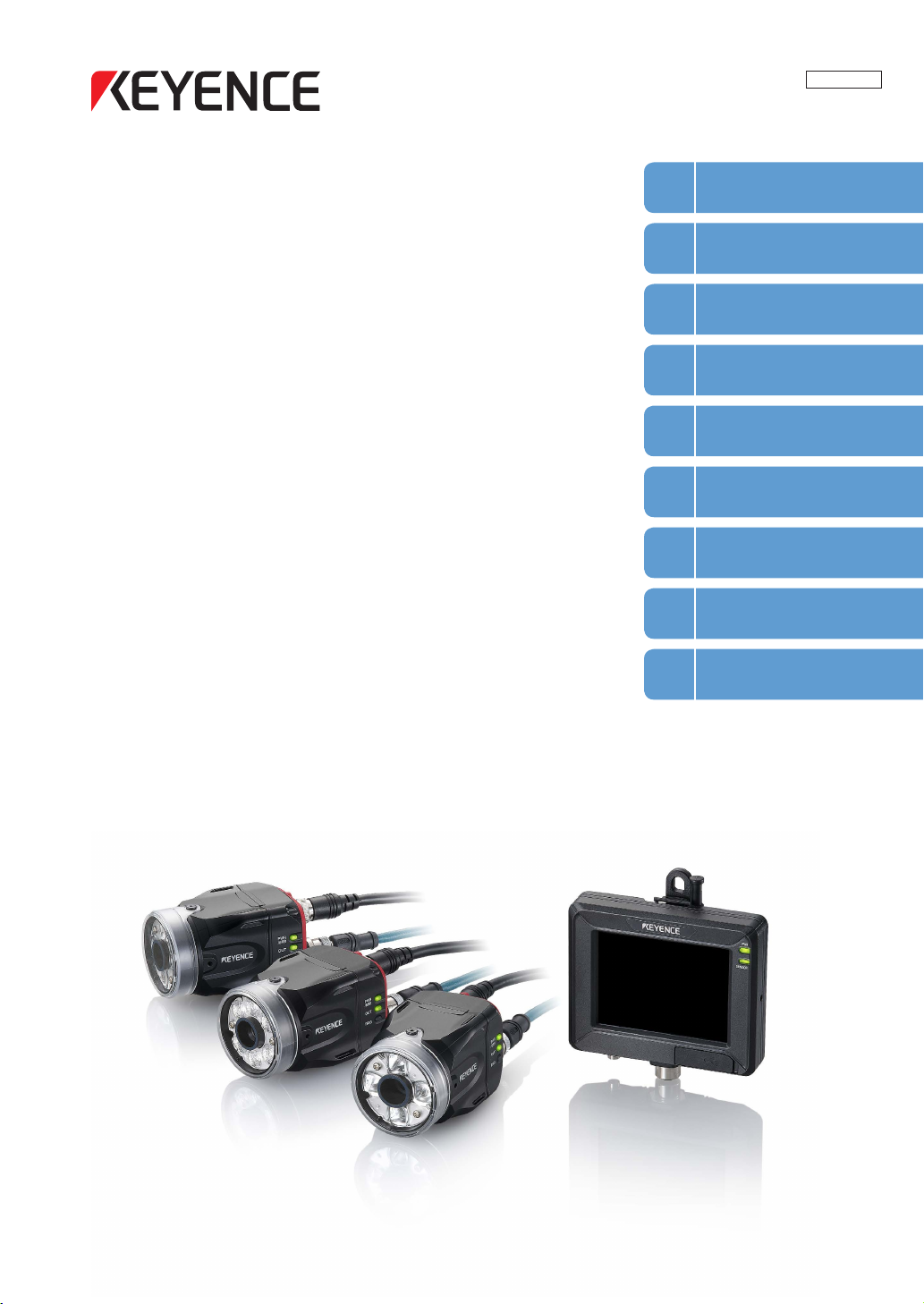
Vision Sensor
Getting Started
1
Installation and
2
Connection
Basic Operation
3
Settings Navigator
4
(Setting the Judgment Condition)
206GB
IV Series
User’s Manual
(Monitor)
Read this manual before use.
After you read this manual, keep it in a safe place for future
reference.
Operating/Adjusting
5
Useful Features/
6
Various Functions
Controlling with
7
the Input/Output Line
Specications
8
Status Table,
A
Troubleshooting
Introduction
Introduction
Read this manual before using the product in order to achieve maximum performance.
Keep this manual in a safe place after reading it so that it can be used at any time.
Symbols
The following symbols alert you to important messages.
Be sure to read these messages carefully.
It indicates a hazardous situation which, if not avoided, will result
in death or serious injury.
It indicates a hazardous situation which, if not avoided, could
result in death or serious injury.
It indicates a hazardous situation which, if not avoided, could
result in minor or moderate injury.
It indicates a situation which, if not avoided, could result in
product damage as well as property damage.
It indicates cautions and limitations that must be followed during
operation.
It indicates additional information on proper operation.
It indicates tips for better understanding or useful information.
It indicates the reference pages in this manual or the reference pages in separate manuals.
Cautions
(1) Unauthorized reproduction of this manual in whole or part is prohibited.
(2)
The contents of this manual may be changed for improvements without prior notice.
(3) An utmost effort has been made to ensure the contents of this manual are as complete as possible.
If there are any mistakes or questions, please contact a KEYENCE ofce listed in the back of the
manual.
(4) Regardless of item (3), KEYENCE will not be liable for any effect resulting from the use of this unit.
(5) Any manuals with missing pages or other paging faults will be replaced.
The company names and product names used in this manual are registered trademarks or the trademarks
of their respective companies.
Safety Information for IV Series
Safety Information for IV Series
General Precautions
Do not use this product for the purpose to protect a human body or a part of human body.
This product is not intended for use as an explosion-proof product. Do not use this product in
hazardous location and/or potentially explosive atmosphere.
You must verify that the IV Series are operating correctly in terms of functionality and performance
before the start and the operation of the IV Series.
We recommend that you take substantial safety measures to avoid any damage in the event of
a problem occurring.
KEYENCE never warrants the function or performance of the IV Series if it is used in manner that
differs from the IV Series specications contained in this instruction manual or if the IV Series are
modied by yourself.
When the IV Series is used in combination with other instruments, functions and performance
may be degraded, depending on operating conditions and the surrounding environment.
Do not place the instruments, including peripherals, under the rapid temperature change. It may
cause condensation and may damage instruments or peripherals.
Remove the power cable from the power supply if you do not use this product for a long time.
Safety precautions on LED product
Use of controls or adjustments or performance of procedures other than those specied herein
may result in hazardous radiation exposure. Follow the instructions mentioned in this manual.
Otherwise, injury to the human body (eyes and skin) may result.
Do not stare into the direct or specularly reected beam.
Do not disassemble this product. The laser radiation emission from this product is not
automatically stopped when it is disassembled.
Do not direct the beam at people or into areas where people might be present.
Be careful of the path of the LED beam. If there is a possibility that the operator may be exposed
to the specular or diffuse reections, block the beam by installing a protective enclosure.
Install this product so that the path of the LED beam is not as the same height as that of human eye.
206GB
1

Important Instructions
Important Instructions
Observe the following precautions to prevent malfunction of the IV Series and to
ensure that it is used properly.
Precautions on use
The power of this product and instruments connected to this product must be turned off when
the cable is to be installed or removed. Failure to do so may cause an electric shock or a
product damage.
Use this product in the correct supply voltage. Failure to do so may cause a product damage.
For instructions
Do not turn OFF the power while setting the items or saving the settings. Otherwise, all or
part of the setting data may be lost.
Do not let water, dust or oil stick to the camera/light of the sensor. Failure to do so may cause
a malfunction.
The enclosure rating of the monitor (IV-M30) is IP40. This is not designed for water proof so be
careful to operate it.
When this product becomes dirty, do not rub it with a wet cloth, benzene, thinner, or alcohol.
Doing so may change the color or shape of the unit.
If the unit is heavily contaminated, disconnect all the cables including the power supply cable,
wipe off the dirt with a cloth soaked with mild detergent, and then wipe with a soft dry cloth.
For an LCD panel
Do not press the touch panel with the tip of your nail or anything that has a sharp tip such as
a pen or a screwdriver. Doing so may cause damage.
Do not apply shock to the touch panel or press it with excessive force. Doing so may cause
damage.
The LCD panel may have some dots that are always lit (bright dots) or ones that are always
unlit (black dots). This phenomenon is not a problem.
Due to the unique characteristics of an LCD, displaying the same image for a long time may
cause an afterimage.
For USB memory
Use products recommended by KEYENCE.
A USB memory device with a security function cannot be used.
Unplug the USB memory when turning on or off the power of IV Series.
Do not remove the USB memory while the USB is being written on. Otherwise, all or part of
the setting data may be lost or it may cause a damage.
For external master image registration
When the external master image registration is used frequently, set [Write ROM when using “Ext.
Master Save”?] of the input option to [No] for nonvolatile memory protection of the internal
sensor. When the option is set to [Yes], the nonvolatile memory is guaranteed to write for
100,000 times.
For automatic focus function
Automatic focus function is used for adjusting the focusing position at the time of installation.
This will not activate during the operation.
Focusing position can be registered in each program. The program congurations are guaranteed
to switch for 100,000 times. If the focusing position does not need to change for each program,
set [Auto Focus Adj Pos] to [Common] for extending the life-span.
Do not apply shock or vibration during the focusing position adjustment. Failure to do so may
cause a product damage.
2
- IV Series User's Manual (Monitor) -
Important Instructions
Measures to be taken when an abnormality occurs
In the following cases, turn the power OFF immediately. Using the IV Series in an abnormal condition
could cause re, electric shock, or malfunction.
Contact our ofce for repair.
If water or debris enters the IV Series.
If the IV Series is dropped or the case is damaged.
If abnormal smoke or odor emanates from the IV Series.
Precautions on installation
To use this product correctly and safely, avoid installing it in the following locations. Failure to
do so may cause re, electric shock, or malfunction.
Outdoors
Altitude above 2000 m
Locations that are humid, dusty or poorly ventilated
Locations where the temperature is high such as those exposed to direct sunlight
Locations where there are ammable or corrosive gases
Locations where the unit may be directly subjected to vibration or impact
Locations where water, oil, or chemicals may splash onto the unit
To improve the anti-noise feature, install the unit following the precautions below. Otherwise, a
malfunction may occur.
Mount the sensor onto the insulated attached mounting adapter.
Ground the FG cable (drain cable) of the sensor.
Do not mount the unit in a cabinet where high-voltage equipment is already installed.
Mount the unit as far from power lines as possible.
Separate the unit as far as possible from the devices that emit strong electric or magnetic
eld (such as solenoid or chopper).
Separate the I/O signal line from the power line or high-voltage line.
For power supply
Noise superimposed on the power supply could cause malfunction. Use a stabilized DC
power supply congured with an isolation transformer.
When using a commercially available switching regulator, be sure to ground the frame ground
terminal.
Devices including this unit are precision components. Do not apply shock or vibration.
When connecting to a network, let engineers who are knowledgeable about networks handle it.
- IV Series User's Manual (Monitor) -
3

Precautions on Regulations and Standards
Precautions on Regulations and Standards
For IV-500C/IV-500CA/IV-500M/IV-500MA/IV-150M/IV-150MA/ IV-2000M/IV-2000MA
UL Certication
This product is a UL/C-UL Listed product.
UL File No. E301717
Category NRKH, NRKH7
Be sure to consider the following specications when using this product as a UL/C-UL Listed Product.
Use a power supply with Class 2 output dened in NFPA70 (NEC: National Electrical Code).
Power supply/ External input/ Control output shall be connected to a single Class 2 source only.
Use with an over current protection device which is rated 24 V or more and not more than 1A.
Enclosure Type 1 (Based on UL50)
CE Marking
Keyence Corporation has conrmed that this product complies with the essential requirements of
the applicable EC Directive, based on the following specications. Be sure to consider the following
specications when using this product in the Member State of European Union.
EMC Directive (2004/108/EC)
Applicable Standard EMI: EN60947-5-2, Class A
EMS: EN60947-5-2
The length of power I/O cable, Ethernet cable and Monitor cable must be less than or equal to 30m.
Remarks:
These specications do not give any guarantee that the end-product with this product incorporated
complies with the essential requirements of EMC Directive. The manufacturer of the end-product is solely
responsible for the compliance on the end-product itself according to EMC Directive.
Low-Voltage Directive (2006/95/EC)
Applicable Standard: EN62471
4
- IV Series User's Manual (Monitor) -

Precautions on Regulations and Standards
For IV-M30
UL Certication
This product is a UL/C-UL Listed product.
UL File No. E207185
Category NRAQ, NRAQ7
Be sure to consider the following specications when using this product as a UL/C-UL Listed Product.
Use a power supply with Class 2 output dened in NFPA70 (NEC: National Electrical Code).
This product is for use on a at surface of a Type 1 enclosure.
CE Marking
Keyence Corporation has conrmed that this product complies with the essential requirements of
the applicable EC Directive, based on the following specications. Be sure to consider the following
specications when using this product in the Member State of European Union.
EMC Directive (2004/108/EC)
Applicable Standard EMI: EN61326-1, Class A
EMS: EN61326-1
The length of Monitor power cable, Ethernet cable and Monitor cable must be less than or equal to 30m.
Remarks:
These specications do not give any guarantee that the end-product with this product incorporated
complies with the essential requirements of EMC Directive. The manufacturer of the end-product is solely
responsible for the compliance on the end-product itself according to EMC Directive.
- IV Series User's Manual (Monitor) -
5
Version of the IV Series
Version of the IV Series
You can download the most recent operation software for the sensor (IV-150/500/2000) and the monitor
(IV-M30) from the KEYENCE web site.
Please refer to the description on the homepage for the introduction method.
URL : http://www.keyence.com/
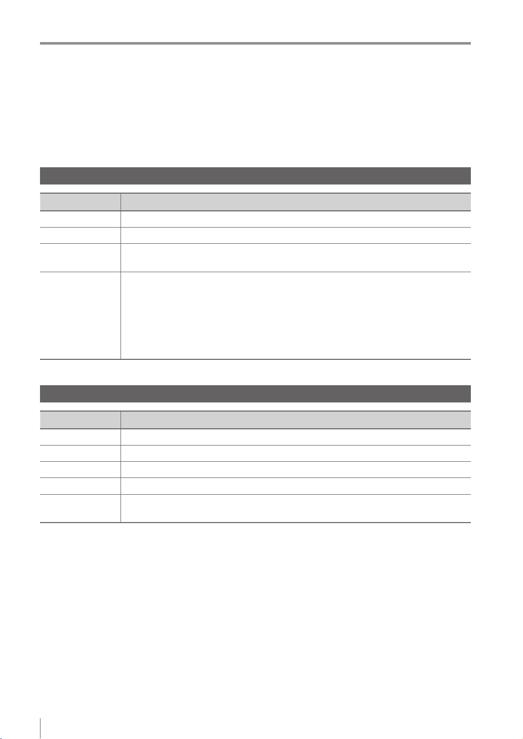
Operation software of the sensor (IV-150/500/2000)
Version Description
R1.00.00 The initial version.
R1.01.00 The processing time has been speeded up.
R1.10.00
R2.00.00
The processing time and the response time to program switching input have been
speeded up.
This is the version of this document.
The following functions have been added.
Logic output
Total status NG output
RUN output
FTP client function
Field network (EtherNet/IP, PROFINET)
Operation software of the monitor (IV-M30)
Version Description
R1.00.00 The initial version.
R1.01.01 Compatibility with Chinese (Simplied) / Chinese (Traditional).
R1.02.00 Compatibility with German.
R1.10.00 Compatibility with Tool Auto Tuning using a registration information le (*.ivt).
R2.00.00
This is the version of this document.
Compatibility with Italian / French / Spanish / Portuguese / Korean.
6
- IV Series User's Manual (Monitor) -
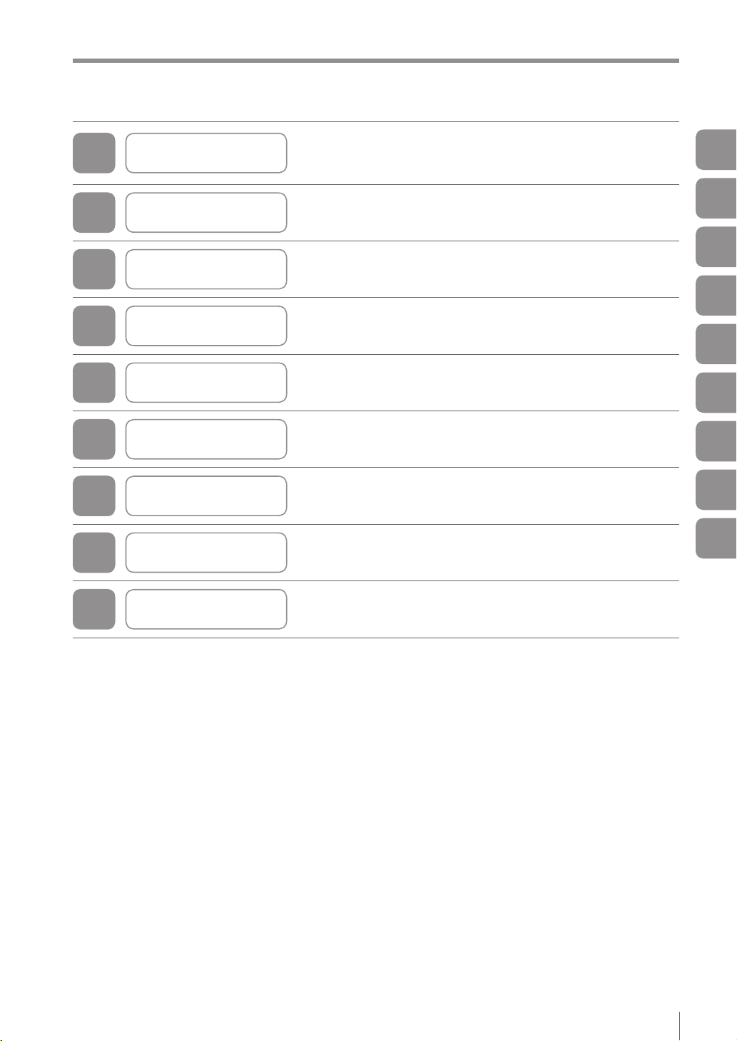
Structure of This Manual
This chapter explains the system conguration and overview
1
Getting Started
of IV Series, package contents, and names and functions of
each part.
Structure of This Manual
1
2
3
4
5
6
7
8
A
Installation and
Connection
Basic Operation
Settings Navigator
(Setting the Judgment Condition)
Operating/Adjusting This chapter explains how to operate and adjust the IV Series.
Useful Features/
Various Functions
Controlling with
the Input/Output Line
Specications This chapter explains specications and dimensions.
Appendices
This chapter explains how to mount the sensor and monitor,
and explains connection procedures.
This chapter explains the basic operation and operation ow
of the IV Series.
This chapter explains how to set the sensors using
the Settings Navigator.
This chapter explains the useful and detailed features.
This chapter explains how the input and output terminals
control each operation.
This chapter explains error messages and troubleshooting, etc.
2
3
4
5
6
7
8
A
- IV Series User's Manual (Monitor) -
7

Contents
Contents
Introduction
Symbols
Cautions
Safety Information for IV Series..............................1
General Precautions ...........................................1
Safety precautions on LED product ....................1
Important Instructions .............................................2
Precautions on use .............................................2
Measures to be taken when an abnormality
occurs..................................................................3
Precautions on installation ..................................3
Precautions on Regulations and Standards ...........4
For IV-500C/IV-500CA/IV-500M/IV-500MA/
IV-150M/IV-150MA/IV-2000M/IV-2000MA ........... 4
UL Certication ................................................4
CE Marking ......................................................4
For IV-M30 ..........................................................5
UL Certication ................................................5
CE Marking ......................................................5
Version of the IV Series ..........................................6
Operation software of the sensor
(IV-150/500/2000) ...............................................6
Operation software of the monitor (IV-M30) ........6
Structure of This Manual ........................................7
Contents .................................................................8
Chapter 1 Getting Started
System Conguration ..........................................1-2
Basic congurations of IV Series .....................1-2
Connecting the monitor and single sensor ...1-2
Connecting the monitor and
multiple sensors ............................................1-3
Overview of IV Series ..........................................1-4
IV Series...........................................................1-4
Using with the intelligent monitor (IV-M30) ...1-4
Using with the IV-Navigator (IV-H1) ..............1-5
Judgment processing ow................................1-6
Checking the Package Contents .........................1-8
Sensor ..............................................................1-8
Optional parts for the sensor ............................1-8
Dome attachment .........................................1-8
Polarized visible light lter attachment..........1-8
Infrared polarization lter attachment ...........1-8
Power I/O cable (M12 12pin - strand wire) ...1-9
Mounting adapter ..........................................1-9
Front cover (for replacement) .......................1-9
Bracket..........................................................1-9
Intelligent Monitor ...........................................1-10
Optional parts for the monitor.........................1-10
Monitor power cable
(M8 4pin - strand wire) ................................1-10
Protection sheet ..........................................1-10
USB memory (1GB) ....................................1-10
Stylus ..........................................................1-10
Wall mounting adapter ................................1-11
Panel mounting adapter..............................1-11
DIN mounting adapter.................................1-11
Communication Cable ....................................1-12
Monitor cable (M12 4pin - M12 4pin) ..........1-12
Ethernet cable (M12 4pin - RJ-45)..............1-12
Name and Function of Each Part ......................1-13
Sensor ............................................................1-13
Name and function of each part of
the sensor ...........................................1-13
Operation of the indicator light ............1-14
Monitor ...........................................................1-15
Chapter 2 Installation and Connection
Mounting the Sensor ...........................................2-2
Checking the view and installed distance ........2-2
Mounting the sensor.........................................2-4
Mounting the mounting adapter ....................2-4
Mounting on the wall .............................2-4
Mounting from the jig side .....................2-4
Mounting the sensor onto the mounting
adapter..........................................................2-4
Unmounting the sensor ....................................2-5
Mounting the attachment..................................2-6
Using the dome attachment ..........................2-6
Mounting the dome attachment ............2-6
Installed distance of the dome
attachment ............................................2-6
Using the polarizing lter attachment............2-7
Mounting the Monitor ...........................................2-8
Mounting to a wall ............................................2-8
Hanging on the hook.....................................2-8
Mounting with the wall mounting adapter .....2-8
Unmounting from the wall mounting adapter
Mounting to a panel........................................2-10
Mounting to a panel ....................................2-10
Panel cutting dimension..............................2-10
Mounting to the DIN rail .................................2-11
Mounting using DIN mounting adapter .......2-11
Unmounting from
the DIN mounting adapter...........................2-11
Cables ...............................................................2-12
Connecting the power I/O cable of
the sensor ......................................................2-12
Specication of I/O circuit and current of
the sensor ......................................................2-14
Input circuit .................................................2-14
No-voltage input
(When the NPN output is selected) ....2-14
Voltage input
(When the PNP output is selected) .....2-14
Output circuit...............................................2-14
When the NPN output is selected .......2-14
When the PNP output is selected .......2-14
Connecting the power cable of the monitor....2-15
Connecting the sensor and the monitor .........2-16
Connecting directly .....................................2-16
Connecting via network ..............................2-16
Connecting the monitor cable/
Ethernet cable.............................................2-17
...2-9
8
- IV Series User's Manual (Monitor) -

Contents
Chapter 3 Basic Operation
Overview of Screen and Operation .....................3-2
Basic Operation Flow ..........................................3-4
Operation when the Power is Turned on .............3-5
Operation ow when the power is turned on ....3-5
Operation for initial startup of the monitor
(Direct Connection) ..........................................3-6
Operation for initial startup of the monitor
(Network Connection) ......................................3-7
Setting the network address of the monitor
Searching for a sensor to be connected .......3-8
Specifying sensor to be connected by IP
address .......................................................3-10
Operation for initial startup of the sensor .......3-11
Setting to the Factory Default ............................3-12
Initializing the sensor......................................3-12
Initializing the monitor ....................................3-13
Basic Operation for the Monitor .........................3-14
Editing the value with the slider......................3-14
Editing the tool window ..................................3-15
Inputting characters........................................3-16
Selecting the le in the USB memory.............3-17
...3-7
Chapter 4 Settings Navigator
(Setting the Judgment Condition)
Settings Navigator ...............................................4-2
Flow in the Settings Navigator .........................4-2
Basic Operation of the Settings Navigator...........4-3
Starting the Settings Navigator ........................4-3
Settings Navigator screen and operation ow
Displaying the Settings Navigator guide ..........4-5
Finishing the Settings Navigator ......................4-5
Finishing by completing all steps ..................4-5
Finishing without completing the step ...........4-5
1. Image Optimization (Clearly Image a Target)
Setting the Image Optimization ........................4-6
Main screen for the Image Optimization ..........4-7
Setting the Trigger Options ..............................4-8
Settings for the Trigger Options ....................4-8
Setting the Trigger Options .........................4-10
Auto Brightness Adjustment ...........................4-11
Focus Adjustment...........................................4-12
Focus adjustment for
the auto focusing type.................................4-12
Focus adjustment for
the manual focusing type ............................4-14
Extended functions for
the Image Optimization ..................................4-16
Items of extended functions for
the Image Optimization ...............................4-16
Imaging Area...............................................4-17
Advanced Brightness Adjustment ...............4-18
Lighting .......................................................4-18
Color Filters (color type only) ......................4-19
Digital Zoom (monochrome type only) ........4-19
2. Master Registration (Registering an Image
as a Reference for Judgment) ...........................4-20
Main screen for the Master Registration ........4-20
...4-4
...4-6
Registering the master image ........................4-21
Extended functions for
the Master Registration ..................................4-22
Items of extended functions for
the Master Registration...............................4-22
Master image registration from
the image history in the sensor ...................4-22
Registering from the image in
the USB memory ........................................4-24
When using a batch backup le
(*.iva) ..................................................4-24
When using an image capture le
(*.ivp) ..................................................4-25
Brightness correction ..................................4-26
3. Tool Settings
(Setting the Judgment Method for Targets) .......4-28
Selecting a tool according to
its intended purpose .......................................4-28
Types of tools .................................................4-28
Main screen for the Tool Settings ...................4-30
Adding/Editing/Deleting a tool ........................4-31
Adding a tool ...............................................4-31
Editing a tool ...............................................4-31
Deleting a tool .............................................4-31
Outline tool .....................................................4-32
Setting items for the Outline tool.................4-32
Setting the Outline tool ...............................4-33
Setting a search region .......................4-35
Settings for disabling outlines .............4-35
Setting a sensitivity .............................4-36
Extended functions for the Outline tool .......4-37
Rotation Range ...................................4-38
Search Algorithm ................................4-38
Tool Name ...........................................4-39
Color Area/Area tool .......................................4-40
Setting items for the Color Area/Area tool
Setting the Color Area/Area tool .................4-42
Mask settings ......................................4-45
Setting the upper limit .........................4-46
Extended functions of
the Color Area/Area tool .............................4-48
Advanced Color Extraction/
Advanced Brightness Extraction .........4-49
Tool Name ...........................................4-49
Fixed Reference Area .........................4-50
Position Adjustment tool .................................4-51
Setting items for
the Position Adjustment tool .......................4-52
Setting the Position Adjustment tool ...........4-53
Setting a search region .......................4-55
Settings for disabling outlines .............4-55
Setting a sensitivity .............................4-56
Extended functions for
the Position Adjustment tool .......................4-57
Rotation Range ...................................4-57
Extended functions for the Tool settings ........4-58
Items of extended functions for
the Tool settings ..........................................4-58
Copy Tool ....................................................4-58
...4-40
- IV Series User's Manual (Monitor) -
9

Contents
4. Output Assignment
(Setting Details of Outputting to Output Line) ....4-60
Main screen for the Output Assignment .........4-60
Setting range of the Output Assignment ........4-60
Default value .......................................4-60
Setting the Output Assignment.......................4-61
Extended functions for
the Output Assignment ...................................4-62
Extended functions items for
the Output Assignment ...............................4-62
Logic Settings .....................................4-63
Total Status Conditions .......................4-65
Display Method of Extended Functions Menus
...4-66
Chapter 5 Operating/Adjusting
Starting an Operation ..........................................5-2
Turning on the power and
starting an operation ........................................5-2
Exiting the sensor settings and
starting an operation ........................................5-2
Overview of the Operation Screen ......................5-3
Names and Functions of the Operation Screen
Menu Screen ....................................................5-4
Switching the display to the full-screen mode
Enlarging the image display .............................5-6
Selecting the tool whose information to be
displayed ..........................................................5-6
Selecting the tool from
the pull-down menu ..............................5-6
Selecting the tool by tapping it on
the monitor ............................................5-6
Selecting a display method for tools ................5-7
Display methods for tools .............................5-7
For color type ........................................5-7
For monochrome type ...........................5-8
Displaying the statistical information ..............5-10
Displaying the statistical information...........5-10
Hiding the statistical information .................5-11
Displaying the histogram ................................5-12
Displaying the histogram ............................5-12
Hiding the histogram ...................................5-13
Adjusting Thresholds for Judgment ...................5-14
Tool Auto Tuning (Automatically
Adjusting the Judgment Condition)....................5-15
Using the images taken in
the Test mode .....................................5-15
Using the image history saved in
the sensor ...........................................5-15
Using the image les saved in
the USB memory ................................5-15
Operation ow for the Tool Auto Tuning .........5-16
Starting and nishing the Tool Auto Tuning ....5-16
Registering the OK/NG images to be used
for the Tool Auto Tuning .................................5-18
Registering the images taken in
the Test mode .............................................5-18
Registering the images from
the image history saved in the sensor ........5-20
...5-4
...5-5
Registering the images from
the le saved in the USB memory ..............5-22
Conrming or deleting the images
registered for the Tool Auto Tuning ................5-25
Tool Auto Tuning by
the previous registration information ..............5-26
Tool Auto Tuning by
the registration information le .......................5-28
Stabilizing the Judgment Process .....................5-32
Stabilizing the judgment process by
taking a clear image of the target ...................5-32
Imaging the target widely ............................5-32
Adjusting the installed distance (WD)
Using the digital zooming function ......5-32
Correcting the distorted images due to
the installation .............................................5-33
Achieving adequate image brightness ........5-33
If the brightness cannot be adjusted
in the Auto Brightness Adjustment ......5-33
If the brightness cannot be adjusted
due to uneven brightness ...................5-33
Achieving good focus..................................5-34
If good focus cannot be achieved by
the Auto Focus Adjustment .................5-34
Reducing the image blur .............................5-34
Reducing the shininess of the glossy or
metal surface ..............................................5-35
Using the Auto Brightness Adjustment
Using the dome attachment ................5-35
Using the polarizing lter attachment
Installing the sensor at an angle .........5-35
Adjusting the color tint (for color type only)
Reducing the effect of
illumination variation ...................................5-36
Stabilizing by correcting
the misaligned target position ........................5-36
Tool settings ........................................5-36
Processing during an operation ..........5-36
Stabilizing the position adjustment .................5-37
Basic adjustments ...............................5-37
If the target tilts and the position
adjustment becomes unstable ............5-37
If the position adjustment becomes
unstable due to the effect of
the unwanted outlines .........................5-37
If the outline of the reference target
cannot be detected .............................5-38
Stabilizing the Outline tool..............................5-38
Basic adjustments ...............................5-38
If the outline cannot be detected
when the target becomes
out of position .....................................5-38
If the detection becomes unstable
due to the effect of the unwanted
outline other than the target ................5-38
If the target tilts and the outline
cannot be detected .............................5-39
If the match rate difference
between the high and
low-quality-targets is small ..................5-39
...5-32
...5-35
...5-35
...5-36
10
- IV Series User's Manual (Monitor) -

Contents
If the outline of the target cannot
be detected .........................................5-39
Stabilizing the Color Area/Area tool ...............5-39
Basic adjustments ...............................5-39
If the color you wish to judge cannot
be extracted ........................................5-39
If the area search becomes
unstable due to unwanted colors
Shortening the Processing Time........................5-40
being extracted ...................................5-39
For the processing time..................................5-40
Flow of the internal process ................5-40
Shortening the imaging processing time ........5-41
Selecting the tool............................................5-41
Shortening the processing time of each tool ..5-41
Shortening the processing time of
the Outline tool............................................5-41
Shortening the processing time of
the Color Area/Area tool .............................5-42
Shortening the processing time of
the position adjustment ...............................5-42
Chapter 6
Useful Features/Various Functions
List of the Useful Features...................................6-2
Useful features while running ...........................6-2
Useful features during installation/adjustment
Displaying the Sensor Setup Menu Screen .........6-7
Changeover for a Target (Program Functions) ....6-8
Overview of the program functions ..................6-8
Things can be performed with
the program functions ......................................6-8
Preparing the program functions ......................6-9
Preparation ow ............................................6-9
Preparation procedures ................................6-9
Using the program functions
(changing over) ..............................................6-10
When the [Monitor/PC] is selected in
the Program Switch Method .......................6-10
When the [External IN] is selected in
the Program Switch Method .......................6-11
Editing a program name .................................6-12
Copying a program.........................................6-12
Initializing a program ......................................6-13
Sensor Image History (Conrming
the Images whose Status Result is NG) ............6-14
Displaying the Sensor Image History screen
Displaying from the run screen ...........6-14
Displaying from
the Sensor Setup Menu screen ..........6-14
Loading and conrming the saved images.....6-15
Clearing the saved images.............................6-16
Changing the logging conditions of
the image history ............................................6-17
Saving the Sensor Settings and Images to
a USB Memory ..................................................6-18
Installing/Removing the USB memory ...........6-18
Installing the USB memory .........................6-18
Removing the USB memory .......................6-18
...6-4
...6-14
Displaying the USB Memory screen ..............6-18
Displaying from the run screen ...........6-18
Displaying from
the Sensor Setup Menu screen ..........6-18
Saving the sensor settings or
the image history ............................................6-19
Backing up in a batch .................................6-19
Saving the image history individually ..........6-20
Transferring the settings backed up in
the USB memory to the sensor ......................6-21
Capturing the monitor screen and
saving to the USB memory ............................6-23
Enabling the screen capturing function.......6-23
Capturing the screen ..................................6-23
Folder composition and le naming rules.......6-24
Setting the Extended Functions of the Sensor
Sensor advanced settings ..............................6-25
Environmental .............................................6-25
Setup Adjustment........................................6-25
Program ......................................................6-25
System ........................................................6-25
I/O Settings ....................................................6-26
Input Settings ..............................................6-26
Output Settings ...........................................6-27
Polarity ........................................................6-28
I/O Monitor ..................................................6-28
Device settings ...............................................6-29
Device Name ..............................................6-29
Password Lock ...........................................6-30
Network Settings ............................................6-31
Advanced Network Settings ...........................6-32
FTP .............................................................6-32
FTP Destination Settings ....................6-33
Transfer Condition Settings ................6-34
Transfer Destination Folder Settings
Field Network ..............................................6-37
Tilt Correction .................................................6-38
Rotate 180° ....................................................6-40
White Balance (for color type only) ................6-41
Program Switch Method .................................6-42
Auto Focus Adjustment Position
(auto focus type only) .....................................6-42
Sensor Information .........................................6-43
Initializing the sensor......................................6-44
Updating the sensor .......................................6-44
Setting the Advanced Monitor Information.........6-45
Monitor Settings .............................................6-45
Sensor Connect ..........................................6-45
Monitor Device Settings ..............................6-45
Monitor Environment...................................6-45
System ........................................................6-45
Sensor Connect .............................................6-46
When directly connecting with the sensor ..6-46
When connecting with the sensor
via a network...............................................6-46
Network Settings ............................................6-48
Display Settings .............................................6-49
Touch Screen Lock.........................................6-50
Language .......................................................6-51
Time ...............................................................6-51
...6-25
...6-35
- IV Series User's Manual (Monitor) -
11

Contents
Backlight.........................................................6-52
Touch Panel Calibration .................................6-52
Monitor Information ........................................6-53
Initialize Monitor .............................................6-53
Update Monitor...............................................6-53
Chapter 7
Controlling with Input/Output Line
Controlling Timing of Judgment with Triggers......7-2
External trigger .................................................7-2
Internal trigger ..................................................7-3
Operating in the shortest cycle .....................7-3
Importing the Status Output.................................7-4
Importing the total status /
total status NG output ......................................7-4
Importing the individual status output of
each detection tool / logic.................................7-5
Changing the timing of the status output..........7-6
Cancelling One-Shot output..........................7-6
Changing Over ....................................................7-7
Registering the Master Image .............................7-8
Clearing Errors ..................................................7-10
Operations when Power of the Sensor is
Turned on ..........................................................7-11
Input Response Time.........................................7-12
Response time for the switch program
input ............................................................7-12
Response time for the external master
registration input .........................................7-12
Response time for the error clear input ......7-12
Description for symbols ..............................7-12
Chapter 8 Specications
Specications ......................................................8-2
Sensor ..............................................................8-2
Intelligent Monitor .............................................8-4
Dimensions ..........................................................8-6
Sensor ..............................................................8-6
Optional parts for the sensor ............................8-7
Dome attachment .........................................8-7
Polarizing lter attachment ...........................8-8
Power I/O cable ............................................8-8
Mounting adapter ..........................................8-8
Front cover....................................................8-8
Bracket..........................................................8-9
Intelligent Monitor ...........................................8-10
Optional parts for the monitor.........................8-12
Monitor power cable ...................................8-12
Protection sheet ..........................................8-12
Stylus ..........................................................8-12
Wall mounting adapter ................................8-12
Panel mounting adapter..............................8-12
DIN mounting adapter.................................8-12
Connection Cable...........................................8-13
Monitor cable ..............................................8-13
Ethernet cable.............................................8-13
Appendices
Status Table ........................................................ A-2
Status table ..................................................... A-2
Displaying and outputting the status result ..... A-4
Displaying and outputting the status result
at the time of position adjustment ................... A-4
Matching Rate of the Outline Tool and
Position Adjustment Tool .................................... A-5
Matching rate at the time of protrusion............ A-5
Cut-off process of the matching rate ............... A-5
Settings List ........................................................ A-6
RUN screen (menu display OFF) .................... A-6
RUN screen (menu display ON)...................... A-6
Sensor Setup Menu screen............................. A-7
Monitor Settings screen .................................. A-9
Sensor Advanced screen .............................. A-11
Sensor Setup screen..................................... A-14
1. Image Optimization ................................ A-14
2. Master Registration................................ A-15
3. Tool Settings .......................................... A-15
4. Output Assignment ................................ A-18
Troubleshooting ................................................ A-19
Error Messages ................................................ A-22
Checking errors by observing
the PWR/ERR indicator light of the sensor ... A-22
Conrming error messages of the monitor .... A-24
Remedy when the Monitor cannot
be Connected with the Sensor ......................... A-28
Remedy when direct connection is
unavailable .................................................... A-28
Remedy when connection via
a network is unavailable ................................ A-29
Conrming the status by observing
the indicator light of the sensor ..................... A-32
LINK/ACT (link/activity) indicator light ........ A-32
STATUS indicator light ............................... A-33
Conrming the status by observing
the SENSOR indicator light of the monitor .... A-34
Other methods of conrming a network
connection ..................................................... A-35
Conrming the existence of
the sensor from the monitor ....................... A-35
If the displayed conrmation
result is “NG” ...................................... A-35
Conrming/Setting the IP address of
the monitor ................................................. A-36
Conrming/Setting the IP address of
the sensor .................................................. A-37
Conrming the router settings.................... A-37
Remedy when data transfer via
FTP is unavailable ..................................... A-38
Initializing the Network Settings
(IP Reset Switch) .............................................. A-40
Settings after initialization ............................. A-40
Connecting method after initialization ........... A-40
For direct connection ......................... A-40
For network connection ..................... A-40
Initializing the network settings ..................... A-40
12
- IV Series User's Manual (Monitor) -

Maintenance ..................................................... A-41
Attaching the protection sheet....................... A-41
Replacing the front cover .............................. A-41
Index ................................................................. A-42
Contents
- IV Series User's Manual (Monitor) -
13

Contents
MEMO
14
- IV Series User's Manual (Monitor) -

1
Getting Started
This chapter explains the system congurations
and overview of IV Series, how to check package
contents, and the name and function of each part.
System Conguration .......................................1-2
Overview of IV Series ........................................1-4
Checking the Package Contents ......................1-8
Name and Function of Each Part ...................1-13
1
Getting Started
- IV Series User's Manual (Monitor) -
1-1
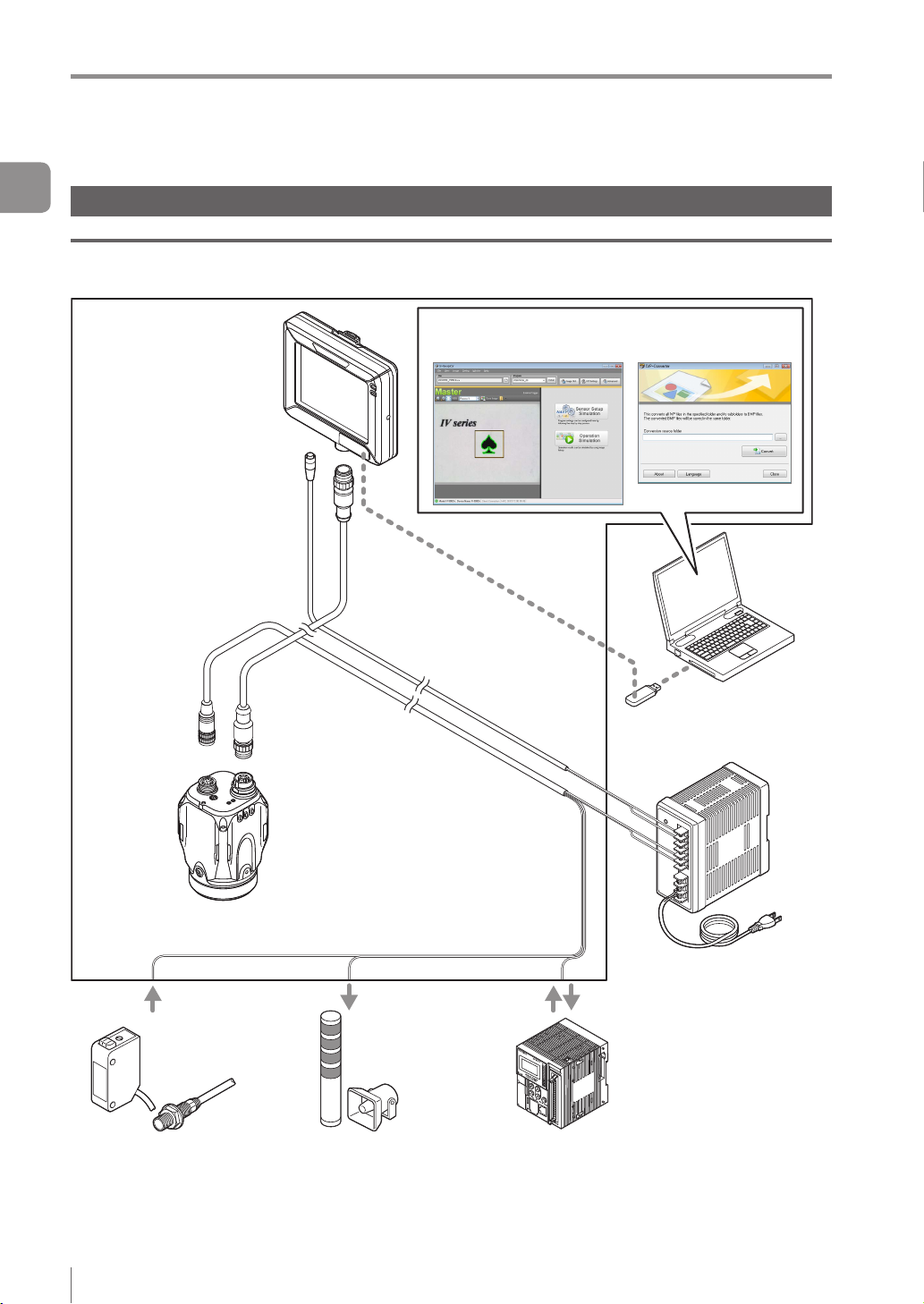
System Conguration
System Conguration
1
Getting Started
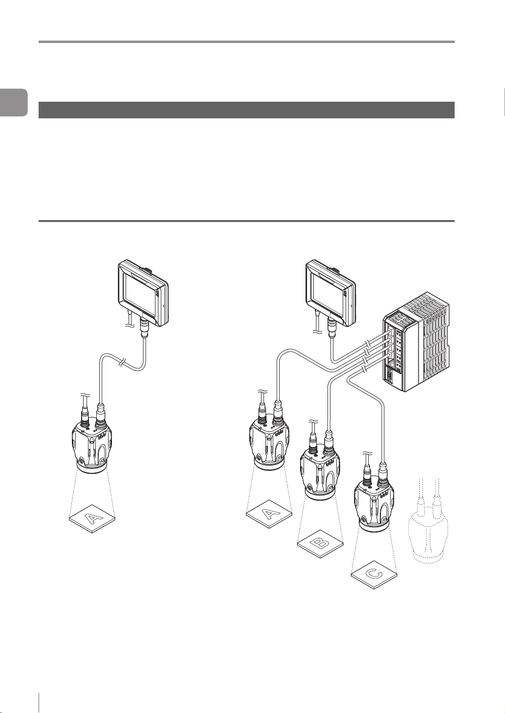
Basic congurations of IV Series
Connecting the monitor and single sensor
IV Series
Intelligent Monitor
IV-M30
Monitor power cable
(2m/5m/10m)
Ethernet communication
Simulator
(IV-Navigator) IVP-Converter
Monitor cable
(2m/5m/10m/20m)
Sensor
IV-500C
IV-500CA
IV-500M
IV-500MA
IV-150M
IV-150MA
IV-2000M
IV-2000MA
Photoelectric/
proximity sensor etc.
Sends the signal to the trigger
input when the target is detected.
(Optional)
Dome attachment
IV-D10
Polarizing lter attachment
OP-87436/OP-87437
Power I/O cable
(2m/5m/10m)
Indicator light/buzzer etc.
Alarm can be output by the
status output function.
USB memory
DC24V power
PLC
PLC can control the trigger input
and the status output function, and
can switch the program number.
1-2
- IV Series User's Manual (Monitor) -
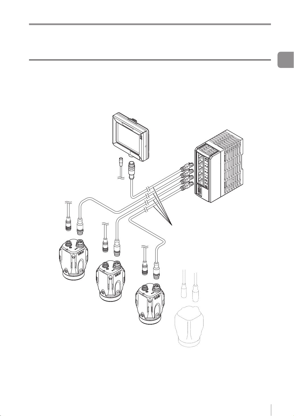
System Conguration
Connecting the monitor and multiple sensors
When the network is connected, the intelligent monitor (IV-M30) can be connected by selecting a single
sensor from among multiple sensors.
* Each sensor requires the power I/O cable.
* IV-M30 requires the power cable.
* A single monitor cannot be connected with multiple sensors at the same time.
Ethernet switch
Ethernet cable
(2m/5m/10m)
1
Getting Started
- IV Series User's Manual (Monitor) -
1-3
Overview of IV Series
Overview of IV Series
1
Getting Started
IV Series
The IV Series is an all-in-one “Vision Sensor” featuring a camera, a light, and a controller. This sensor
can be attached easily so complicated detection operations such as detecting the shapes of parts with a
photoelectric switch can be achieved easily.
Operation condition settings require the intelligent monitor (IV-M30) or the IV software IV-Navigator (IV-H1).
After setting is completed, the sensor can be operated independently.
The sensor with monitor and the sensor with PC are connected via an Ethernet so network connection with
multiple sensors besides direct single connection can be performed.
Using with the intelligent monitor (IV-M30)
Power I/O
Direct connection
Functions of monitor
Setting the sensor
Monitoring the
operation screen
Monitoring the
statistical information
Reading the image
history
Network connection
Ethernet switch
1-4
Functions of sensor
Camera
Light
Image detection
I/O
Saving the image history
- IV Series User's Manual (Monitor) -
Overview of IV Series
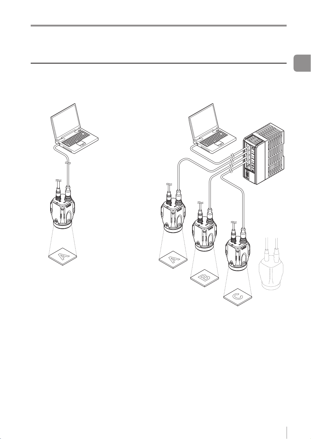
Using with the IV-Navigator (IV-H1)
The IV-Navigator has the same functions as the intelligent monitor (IV-M30).
For details of operations using the IV-Navigator, refer to “IV Series User's Manual (PC Software)”.
Direct connection
Power I/O
Functions of sensor
Functions of IV-Navigator
Setting the sensor
Monitoring the operation
screen
Monitoring the statistical
information
Reading the image history
Simulator
Camera
Light
Image detection
I/O
Saving the image history
Network connection
Ethernet switch
1
Getting Started
- IV Series User's Manual (Monitor) -
1-5
Overview of IV Series
1
Getting Started
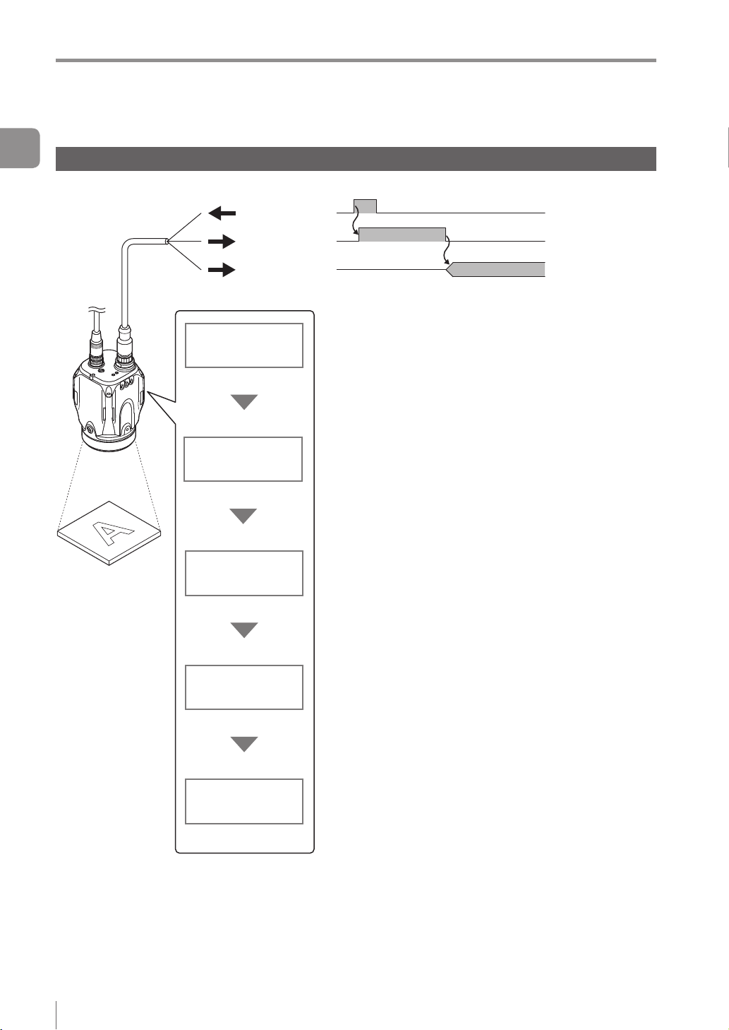
Judgment processing ow
This section describes the basic judgment processing ow of this device.
Trigger input
BUSY output
Total status
output
Trigger input
Imaging
Tool processing
Status output
Inputs the imaging startup signal by synchronizing to the
target position from a photoelectric switch or PLC.
Also, the trigger can be input at a regular interval with an
internal trigger function.
Light up the built-in light and image the target by using the
CMOS image sensor. BUSY output function turns ON.
According to the settings of a detection tool, the image of the target
is scanned for detecting whether a target is high or low quality.
Up to 16 detection tools can be set. Also, misaligned
positions of the target can be corrected by using the
position adjustment tool.
After the detection process is completed, the BUSY output
function turns OFF.
Outputs the status results.
When the total status result is OK, the total status output
is ON.
When the total status result is NG, the total status NG
output is ON.
1-6
Save images
- IV Series User's Manual (Monitor) -
Saves the image to the image history memory in the sensor.
Conditions for saving the image can be selected from “NG
only” or “All”.
Color type can save 100 images, and monochrome type
can save 300 images.

MEMO
Overview of IV Series
1
Getting Started
- IV Series User's Manual (Monitor) -
1-7
Checking the Package Contents
Checking the Package Contents
1
IV Series are constructed by each following model. Check that all the following packed items are packed
Getting Started
for each model you purchased before using.
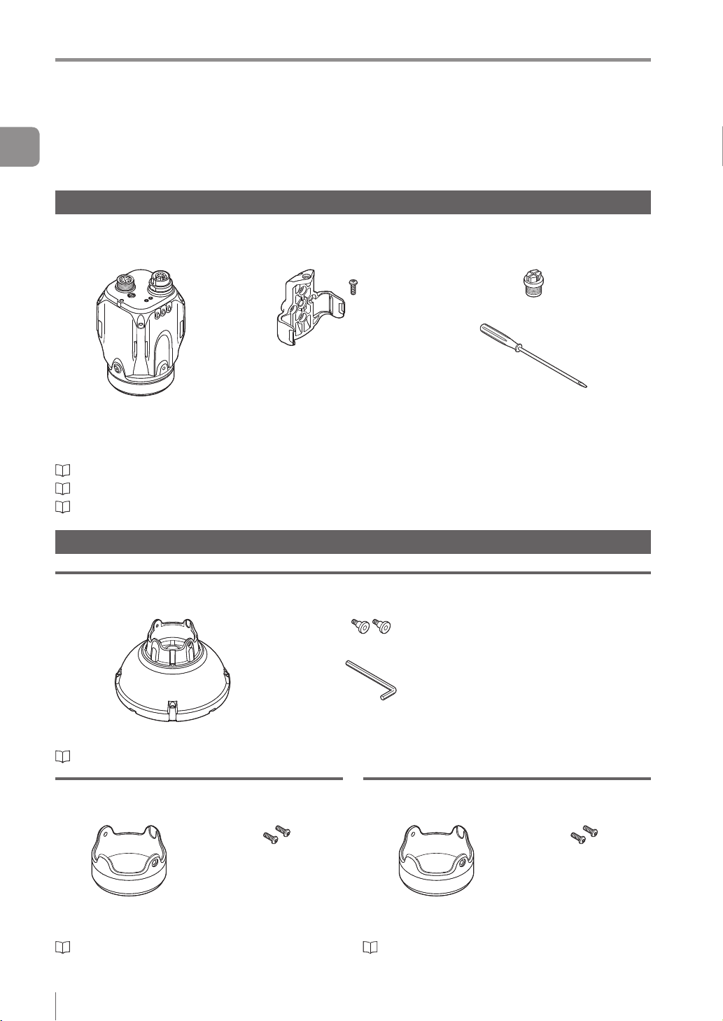
Sensor
IV-500C
IV-500CA
The mounting adapter is mounted with the sensors in the
default factory setting.
“Name and Function of Each Part” (Page 1-13)
“Mounting the Sensor” (Page 2-2)
“Cables” (Page 2-12)
Optional parts for the sensor
IV-150M
IV-150MA
Sensor x 1
IV-500M
IV-500MA
Mounting adapter x 1
Screw for mounting
adapter x 1
IV-2000M
IV-2000MA
Waterproof cap for Ethernet connector x 1
Flathead screwdriver x 1
(Manual focus type only)
Instruction Manual x 1
Dome attachment
IV-D10
Mounting screw x 2
Hexagon wrench
Dome attachment x 1
“Using the dome attachment” (Page 2-6)
(L-shaped) x 1
Polarized visible light lter attachment
OP-87436
Mounting screw x 2
Instruction Manual x 1
Polarized visible light
lter attachment x 1
“Using the polarizing lter attachment” (Page 2-7)
Instruction Manual x 1
Infrared polarization lter attachment
OP-87437
Mounting screw x 2
Instruction Manual x 1
Infrared polarization
lter attachment x 1
“Using the polarizing lter attachment” (Page 2-7)
1-8
- IV Series User's Manual (Monitor) -
Checking the Package Contents
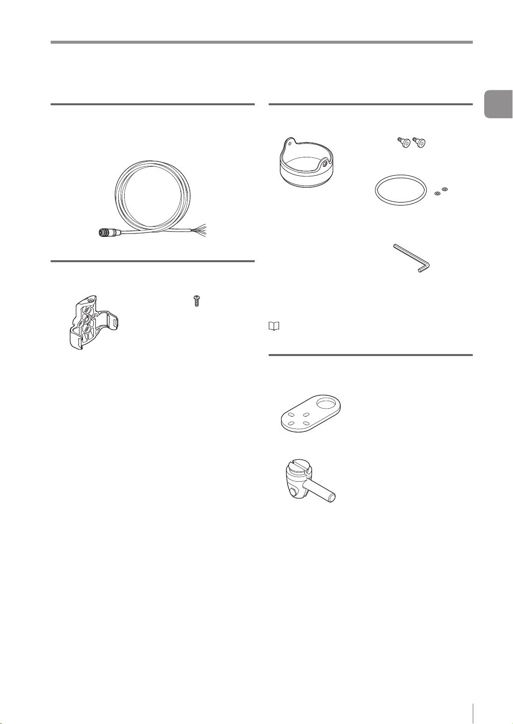
Power I/O cable (M12 12pin - strand wire)
OP-87440 (2m)
OP-87441 (5m)
OP-87442 (10m)
Power I/O cable (M12 12pin - strand wire) x 1
Mounting adapter
OP-87460
Screw for the mounting
adapter x 1
Mounting adapter x 1
Same as accessories for the sensor.
Optional parts in case of loss/damage.
Front cover (for replacement)
OP-87461
Mounting screw x 2
Front cover (for
replacement) x 1
Optional parts for replacement.
“Replacing the front cover” (Page A-41)
O-shaped ring
(Small x 2, Large x 1)
Hexagon wrench (L-shaped) x 1
Instruction Manual x 1
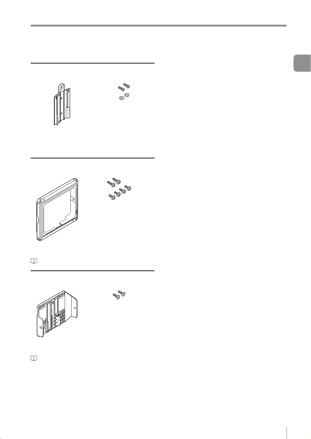
Bracket
OP-87685
Screw for the bracket and
nut x 1
1
Getting Started
Bracket A x 1
Bracket B x 1
- IV Series User's Manual (Monitor) -
Mounting screw x 4
1-9
Checking the Package Contents
1
Getting Started
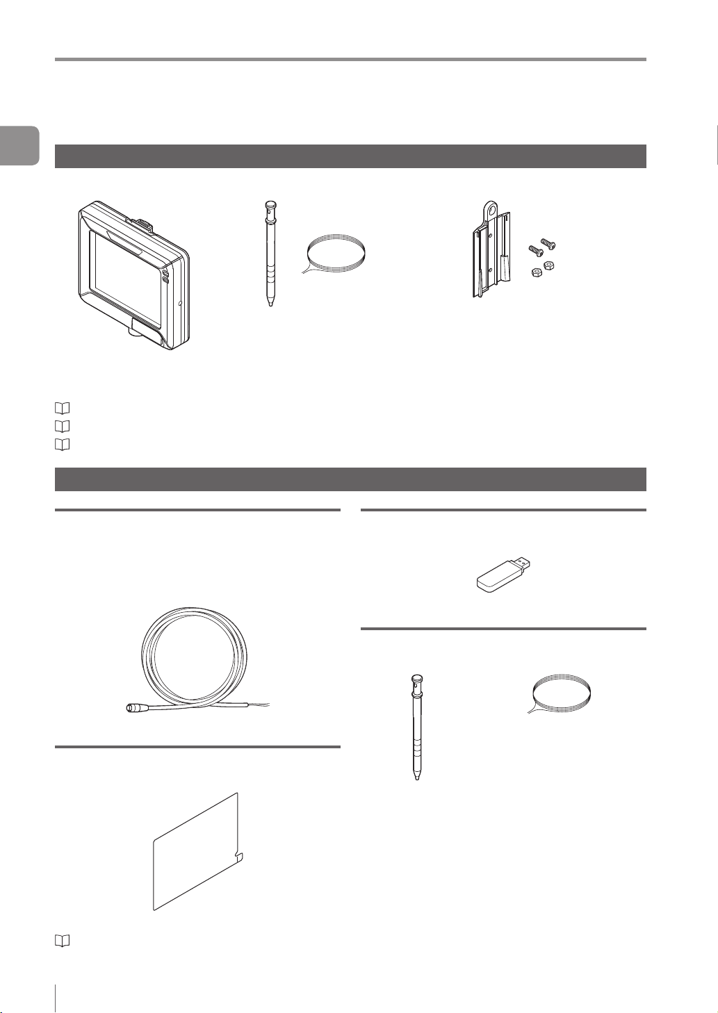
Intelligent Monitor
IV-M30
“Name and Function of Each Part” (Page 1-13)
“Mounting the Monitor” (Page 2-8)
“Cables” (Page 2-12)
Optional parts for the monitor
Monitor power cable (M8 4pin - strand wire)
OP-87443 (2m)
OP-87444 (5m)
OP-87445 (10m)
Monitor x 1
Stylus x 1
String for hanging the stylus x 1
USB memory (1GB)
OP-87502
Wall mounting adapter x 1
Screw for the adapter x 2
Hexagon nut x 2
Instruction Manual x 1
Starting Guide x 1
USB memory x 1
Monitor power cable (M8 4pin - strand wire)
Protection sheet
OP-87463
Protection sheet x 1
“Attaching the protection sheet” (Page A-41)
1-10
- IV Series User's Manual (Monitor) -
Stylus
OP-87462
String for hanging the
stylus x 1
Stylus x 1
Same as accessories for monitors.
Optional parts in case of loss/damage.
Checking the Package Contents
Wall mounting adapter
OP-87464
Screw for the adapter x 2
Hexagon nut x 2
Wall mounting adapter x 1
Same as accessories for monitors.
Optional parts in case of loss/damage.
Panel mounting adapter
OP-87465
Mounting screw (lateral) x 2
Mounting screw (front) x 4
1
Getting Started
Panel mounting
adapter x 1
“Mounting to a panel” (Page 2-10)
DIN mounting adapter
OP-87466
Mounting screw (lateral) x 2
DIN mounting
adapter x 1
“Mounting to the DIN rail” (Page 2-11)
- IV Series User's Manual (Monitor) -
1-11
Checking the Package Contents
1
Getting Started
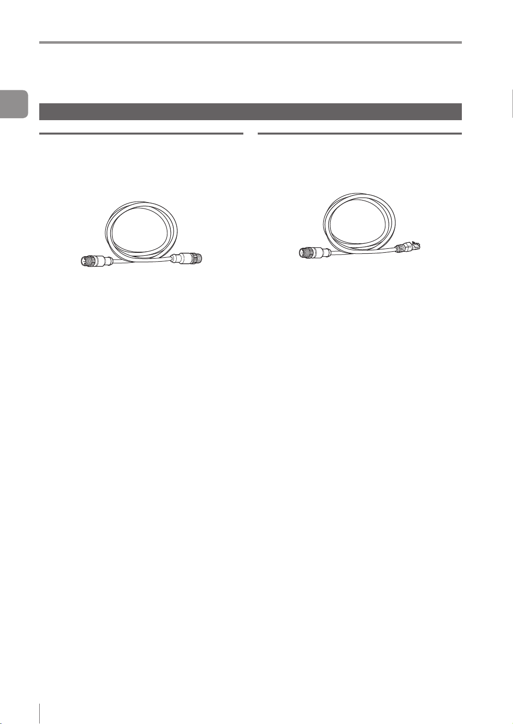
Communication Cable
Monitor cable (M12 4pin - M12 4pin)
OP-87450 (2m)
OP-87451 (5m)
OP-87452 (10m)
OP-87453 (20m)
Monitor cable (M12 4pin - M12 4pin) x 1
Ethernet cable (M12 4pin - RJ-45)
OP-87457 (2m)
OP-87458 (5m)
OP-87459 (10m)
Ethernet cable (M12 4pin - RJ-45) x 1
1-12
- IV Series User's Manual (Monitor) -
Name and Function of Each Part
1
2
3
4
5
6
7
8
Name and Function of Each Part
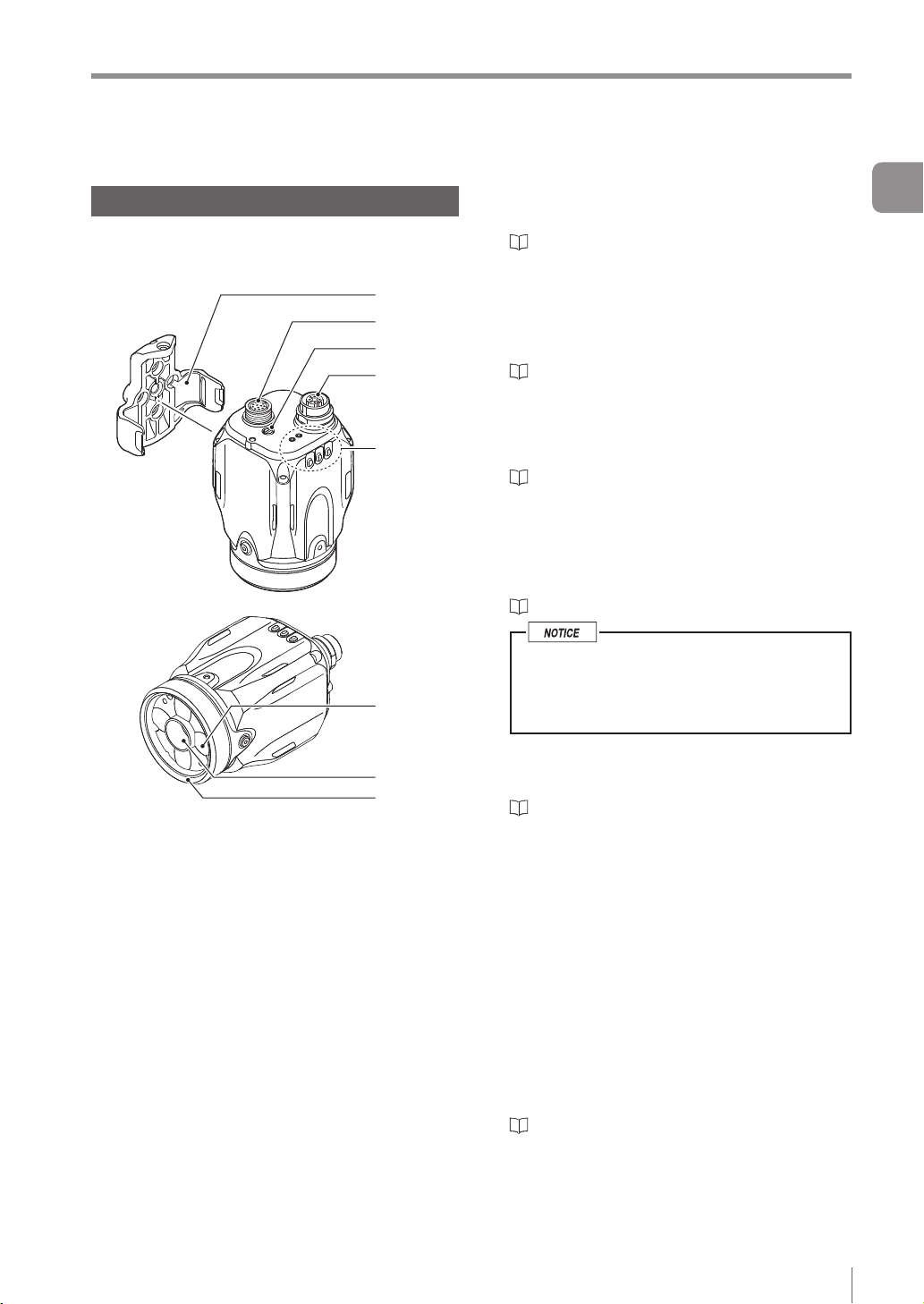
Sensor
Name and function of each part of the
sensor
1 Mounting adapter
Use this for mounting and xing the sensor.
“Mounting the Sensor” (Page 2-2)
2 Connector for power I/O cable
Connector for connecting the power I/O cable.
Use this for supplying the power to the sensor
and for connecting with external devices.
“Cables” (Page 2-12)
3 Focusing position adjustment screw
(manual focus type only)
Adjusts the focus of the displayed image.
“Focus Adjustment” (Page 4-12)
4 Connector for monitor cable/Ethernet cable
Connector for connecting a monitor cable or
Ethernet cable. Use this for connecting the
monitor, PC, or Ethernet switch.
“Cables” (Page 2-12)
When the cable is not connected, attach
the waterproof cap for Ethernet connector
to maintain enclosure rating.
Tightening torque : 0.45 to 0.55 N·m
1
Getting Started
5 Indicator light
- IV Series User's Manual (Monitor) -
Indicates the operating status of the sensor.
“Operation of the indicator light” (Page 1-14)
6 Built-in light
LED light that illuminates the target
7 Camera
Images the object.
8 Front cover
Protects the camera and built-in lights.
The front cover is protected by the protection
sheet (blue) in the default factory setting. Remove
the sheet when the sensor is to be used.
Front cover for replacement is provided for
maintenance.
“Replacing the front cover” (Page A-41)
1-13
Name and Function of Each Part
1
Getting Started
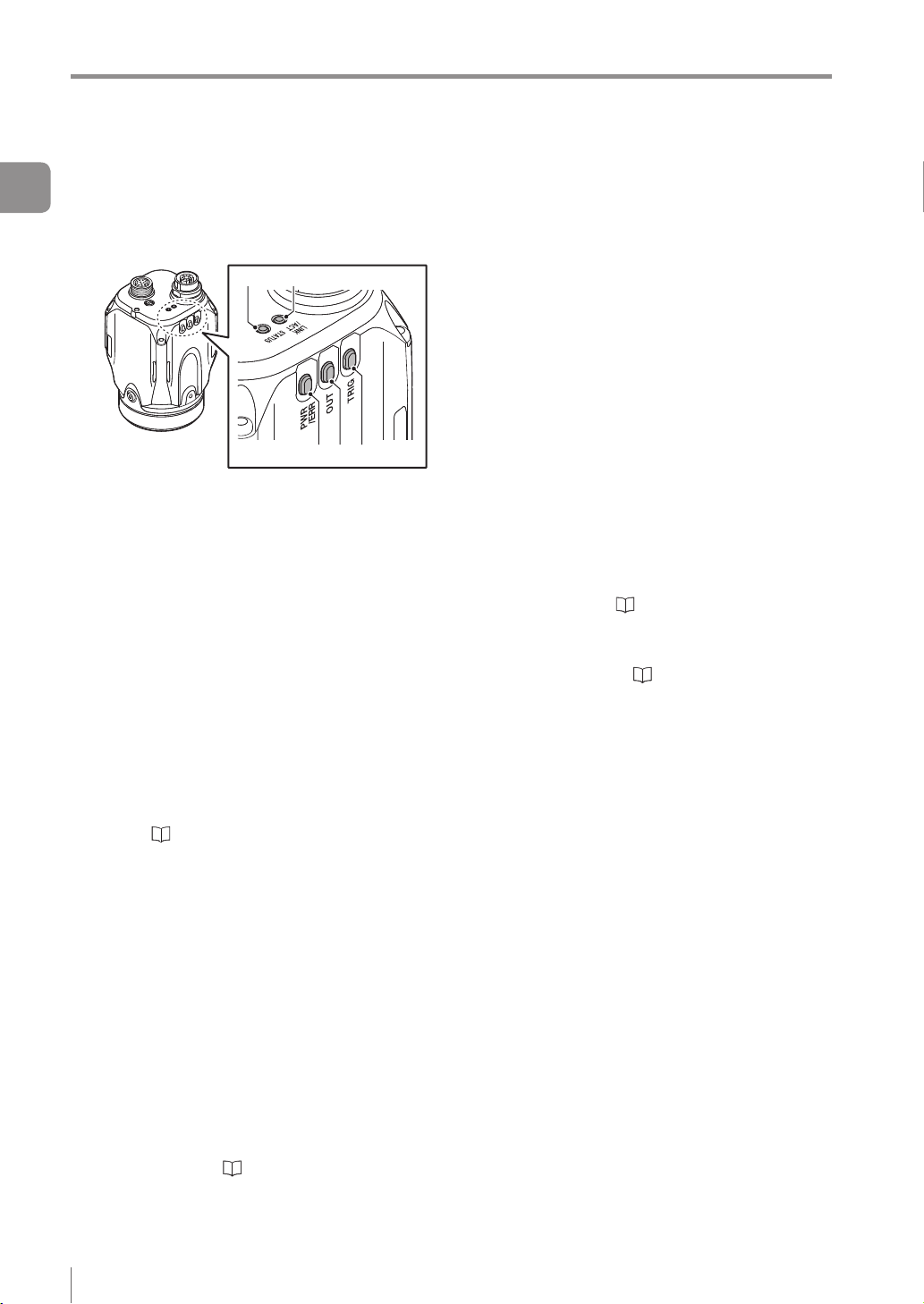
Operation of the indicator light
Details on operations of the indicator light are
shown below.
1 PWR/ERR
Indicates the power supplying status to the
sensor and the error status of the sensor.
Green (ON) ...... Operating.
Green (Blink) .... Setting processing. Operation
Red (ON) .......... Unrecoverable error has
Red (Blink) ....... Recoverable error has
(OFF) ............... Power is not supplied.
For countermeasures when an error occurred,
refer to “Error Messages” (Page A-22).
2 OUT
Indicates the comprehensive result.
Green ...............
Red ..................
(OFF) ............... Setting processing.
Standby status until the rst
Orange (Blink) ..
“Focus adjustment for
4 5
1 2 3
is stopped. Blinks once a
second.
occurred.
occurred.
Adjusting the focusing position
(
manual focus only).
Comprehensive result is “OK”.
Comprehensive result is “NG”.
judge nishes after starting the
operation or after switching
the program number.
Indicates the focusing status
while adjusting the focusing
position with the blinking speed
(manual focus type only).
the manual focusing type”
(Page 4-14)
3 TRIG
Green light lights up (one-shot) according to
input of the internal or external trigger.
4 STATUS
Indicates the connection status within the monitor.
Green (ON) ...... Normally connected with
monitor.
Green (Blink) .... IP address has been retrieved
but the sensor is not correctly
connected with monitor.
(OFF) ............... IP address is not assigned.
Sensor is not correctly
connected with monitor.
Orange (Blink) ..
When the sensor cannot correctly connect with
the monitor, refer to “Remedy when the
Monitor cannot be Connected with the Sensor”
(Page A-28).
5 LINK/ACT
Indicates the linking status within monitor or
Ethernet switch.
Green (ON) ...... Normally linked.
Green (Blink) .... Normally linked, and the data
(OFF) ...............
Indicates the focusing status
while adjusting the focusing
position with the blinking speed
(manual focus type only).
“Focus adjustment for the
manual focusing type” (Page 4-14)
is sending/receiving.
Sensor is not normally linked.
1-14
- IV Series User's Manual (Monitor) -
Loading...