


 Loading...
96M12221
User’s Manual
High-speed, High-precision Digital Micrometer
LS-7600 Series

Preface
This instruction manual provides necessary information on the operation and maintenance of the LS-7600 Series along with precautions. Please read the manual carefully and be sure you understand the information provided before attempting to install and operate the LS-7600 Series. Keep this manual handy for future reference.
Please make sure that the end users are provided with this manual.
Symbols
The following symbols are used for the list of precautions to ensure safety and to prevent personal injury and/or property damage when using the LS-7600 Series.
The following symbols alert you to important messages. Be sure to read these messages carefully.

 DANGER

 WARNING

 CAUTION
Important:
Note:
Tips
Reference:
Failure to follow instructions may lead to death or serious injury.
Failure to follow instructions may lead to injury.
Failure to follow instructions may lead to product damage (product malfunctions, etc.).
Provides important precautions and restrictions on proper operation.
Provides additional information on proper operation.
Provides useful information on proper operation.
Provides reference pages.
General precautions
1.No part of this manual may be reprinted or reproduced in any form or by any means without the prior written permission of KEYENCE CORPORATION.
2.The content of this manual is subject to change without notice.
3.KEYENCE has thoroughly checked and reviewed this manual. Please contact the sales office listed at the end of this manual if you have any questions or comments regarding this manual, or if you find an error.
4.KEYENCE assumes no liability for damages resulting from the use of the information in this manual, item 3 above notwithstanding.
5.KEYENCE will replace any incomplete or incorrectly collated manual.
6.All company names and product names in this manual are registered trademarks or trademarks of their respective owners.

Safety Precautions
■General precautions
•At startup and during operation, be sure to monitor the functions and performance of the LS-7600 Series.
•Take sufficient safety measures to prevent damage to the human body and/or equipment that may be caused if this product should fail to operate properly.
•Do not modify the LS-7600 Series or use it in any way other than as described in the specifications. Its functions and performance are not guaranteed under said conditions.
•When the LS-7600 Series is used in combination with other instruments, its functions and performance may be degraded, depending on the operating conditions and surrounding environment.
•Do not use the LS-7600 Series for the purpose of protecting the human body.
•Do not expose the LS-7600 and peripheral devices to sudden temperature change, as this may cause condensation.
■Precautions
WARNING |
■ Operation |
• Always use the LS-7601 at 24 VDC, otherwise a fire, electric |
|
|
shock or product failure may result. |
•Prepare the applicable AC power supply cable if you use LSS11.
•Secure the GND line of the power cable of the AC power supply stand to protective ground, otherwise an electric shock or product failure may result.
•Do not disassemble or modify the LS-7600 Series. This may cause fire or electric shock.
■ When abnormal conditions are encountered
If the following conditions are encountered, immediately turn off the power. Continuing to use the LS-7600 Series under abnormal conditions may cause fire, electric shock or equipment failure. Contact your nearest KEYENCE sales office for repairs.
•When water or foreign matter enters the controller.
•When the LS-7600 Series is dropped or the housing is damaged.
•When the controller produces smoke or an abnormal smell.
96M12221 |
i |

CAUTION |
■ Usage |
• Be sure to turn off the power to the LS-7600 Series and any |
|
|
connected devices before connecting or disconnecting the cables. |
|
Otherwise, the camera and connected devices may be damaged. |
•Do not turn off the power while setting a parameter. Otherwise, the settings may be partially or completely lost.
•Do not block the ventilation slots on the LS-7600 Series and peripheral devices. A rise in inner temperature may cause equipment failure.
■ Proper environment and conditions
To use the LS-7600 Series properly and safely, do not install the LS-7600 Series in locations with the following conditions. Use of this equipment in an improper environment may cause fire, electric shock, or equipment failure.
•Locations with high humidity, a large amount of dust, or poor ventilation
•Locations where the temperature rises excessively due to direct sunlight, etc.
•Locations where corrosive or flammable gas exists
•Locations where the LS-7600 Series is directly subjected to vibration or impact
•This product is a precision instrument.
Be sure to take appropriate measures against direct vibration or impact.
Otherwise, the optical components in the measurement device may be damaged.
•Locations where water, oil or chemicals may splash the LS7600 Series
•Locations where static electricity is easily built up
■ Countermeasures against Noise
The LS-7600 Series may malfunction or fail to operate due to noise generated from power lines or high-tension lines. If the LS7600 Series is operated close to such noise sources, use a noise filter, wire the cable of the LS-7600 Series in an independent conduit, or locate the LS-7600 Series in an area with proper insulation from noise.
■ Best Management Practice for Perchlorate Materials – California only
When you sell, manufacture and/or waste the products containing perchlorate material in California, the following statement must appear on the exterior of all outer shipping packages and on consumer packages, based on California Code of Regulations.
“Perchlorate Material – special handling may apply, See www.dtsc.ca.gov/hazardouswaste/perchlorate.”
Note: Alternative option is to indicate this statement on your
MSDS or manual accompanying with each product.
This product includes a CR coin type cell containing perchlorate material. If you ship this product (or your product including this product) to California, you must ensure to comply with this regulation.
ii

Note: |
■ Influence of Ambient Operating Temperature |
|
|
Ensure that the ambient operating temperature is constant. A |
|
|
change in the ambient operating temperature may result in |
|
|
measurement errors. If the ambient operating temperature |
|
|
changes by 10°C, it will take approximately 60 minutes for the |
|
|
interior temperature distribution of the LS-7600 Series to be |
|
|
uniform. |
|
|
■ Warming Up |
|
|
Do not operate the LS-7600 Series for approximately 30 minutes |
|
|
after it is turned on. The internal circuitry of the LS-7600 Series is |
|
|
not stable immediately after it is turned on. The measured value |
|
|
drifts gradually as a result. |
|
|
■ Influence of Dust and Dirt |
|
|
A measurement error may result due to dirt, dust, water, or oil in |
|
|
any of the following cases. |
|
|
• Cover glass: Blow off the dirt, dust, water or oil on the cover |
|
|
|
glass with clean air. If the cover glass is excessively dirty, wipe |
|
|
the glass with a soft cloth moistened with isopropyl alcohol. |
|
• |
Target surface: Blow off the dirt, dust, water or oil on the sur- |
|
|
face with clean air or wipe the surface. |
|
• |
Intrusion of dirt, dust, water or oil blown or sprayed into optical |
|
|
sensing area: Install a protection cover or perform air purging. |
|
■ Influence of Vibration |
|
|
The measured value of an object may fluctuate if the object is |
|
|
vibrating. If that happens, increase the averaging number. This |
|
|
will ensure highly accurate measurement. |
|
|
■ Targets |
|
|
The measured value of an object may have an error due to the |
|
|
shape and surface condition. Locate a reference object within the |
|
|
measuring area and use the calibration function of the LS-7600 |
|
|
Series to correct the error if that happens. |
|
|
■ Influence of Air Flow |
|
|
The measured value of an object may fluctuate due to a slow |
|
|
flow of air. In that case, the following countermeasures are |
|
|
effective. |
|
|
• Protect the measuring head with a cover. |
|
|
• Use a fan to mix the air vigorously between the transmitter and |
|
|
|
receiver. |
|
■ Maintenance |
|
|
Do not wipe the LS-7600 Series with a damp cloth or a cloth |
|
|
moistened with benzine or paint thinner. This may cause the |
|
|
discoloration or deformation of the LS-7600 Series. If the LS- |
|
|
7600 Series is excessively dirty, use a tightly squeezed cloth |
|
|
moistened with thin neutral detergent. Then wipe the LS-7600 |
|
|
Series with a soft dry cloth. |
|
■ Precautions for LED
The LS-7010M/LS-7030M/LS-7070M Measuring Head uses an LED light source. Abide by |
|
||
the following precautions when using the unit. |
|
||
|
|
• Do not look at the LED light source for a long time. |
|
|
CAUTION |
|
|
|
The LED used as the light source is classified into class 1 |
|
|
|
|
according to IEC60825-1 standards. Basically the light beam of |
|
|
|
|
|
|
|
the LED is safe, but do not look at the LED for a long time. |
|
|
|
• Do not disassemble the unit. |
|
|
|
The unit does not incorporate a mechanism to stop the emission |
|
|
|
of the LED when the unit is disassembled. Never attempt to |
|
|
|
disassemble the unit, otherwise you will be exposed to LED light. |
iii |
|
|
|
|

Precautions for CE Markings
Keyence confirms that the LS-7600 Series meets EC directive requirements. The LS-7600 Series bears CE markings. Keep the following conditions if the LS-7600 Series is used in European countries.
■ EMC Directives
Keep the following condition so that the LS-7600 Series will satisfy EN61326-1 requirements.
•The power cable and I/O cable connected to the controller are both less than 30m in length.
■Low-voltage Directives
When using the LS-S11 AC Power Supply Stand as a dedicated power supply to the LS7600 Series, keep the following conditions so that the LS-S11 will satisfy EN61010-1 requirements. The LS-S11 satisfies EN60825-1 (LED Class 1) requirements with no conditions attached.
Environment Conditions
Installation category (Overvoltage category): II (see note 1)
Pollution degree: 2 (see note 2)
Operation and Installation Conditions
•The LS-S11 AC Power Stand is a dedicated power supply for the LS-7600 Series. Never use the LS-S11 for other purposes.
•When using the LS-7600 Series in European countries, check that the AC power supply cable satisfies EC directive requirements certified by an authorized third party. Consult your Keyence representative for the AC power supply cable in detail.
•Before turning the LS-7600 Series on, connect the ground terminal of the AC power supply cable to the protective ground terminal of the power supply.
•Be sure to use a time lag fuse rated 250 V, 3.15 A for the replaceable fuse of the LSS11.
Note 1: Installation categories (overvoltage categories) include impulse overvoltage regulations at transient overvoltage levels specified by EC directives.
Installation category II indicates a level where power is provided from fixed installations, such as distribution panels.
Note 2: The pollution degree refers to the level of solid, liquid, or gas contamination that deteriorates the dielectric strength or surface resistance of the LS-7600 Series. Pollution degree 2 indicates the normal indoor environment (free of nonconductive contamination).
iv
About this Manual
The following section provides information on the configuration of each page of this manual along with symbols and terms used in this manual.
Page Configuration and Symbols
Chapter 4 Operation Control
|
|
|
|
|
4-4 Automatic Zero Function |
|
|
|
|
|
|
||||
|
|
|
|
|
The automatic zero function sets measuring values to zero (0.00000) instantly. This func- |
||||||||||
|
|
|
|
|
tion is convenient for zero-point calibration for a variety of target. Furthermore, |
||||||||||
|
|
|
|
|
master calibration is possible by using this function in combination with the offset function. |
||||||||||
|
|
|
|
|
|
|
|
|
|
|
|
|
|
|
|
|
|
|
|
|
Note: |
This function will not be available while the controller is awaiting the result of |
|||||||||
|
|
|
|
|
|
measurement, during which the LCD monitor will display “– – –. – – – –.”) |
|||||||||
Tips: Describes |
|
|
|
|
Tips |
The automatic zero value will not be lost after the LS-7600 Series is turned |
|||||||||
|
|
|
|
||||||||||||
information that will |
|
|
|
|
off. The automatic zero value for each program will be stored. |
|
|
|
|
||||||
|
|
|
Automatic zero settings are made through the following functional components. |
||||||||||||
deepen the user’s |
|
|
|
||||||||||||
4 |
|
|
• Control panel/Remote control console |
|
|
|
|
|
|
||||||
comprehension of |
|
|
• External terminal |
|
|
|
|
|
|
||||||
|
|
• RS-232C interface |
|
|
|
|
|
|
|||||||
the manual along |
|
|
|
■ Control Panel/Remote Control Console |
|
|
|
|
|
|
|||||
|
|
|
|
|
|
|
|
|
|||||||
with other useful |
|
|
|
|
|
|
|
|
|
||||||
|
|
|
If a single measuring value is displayed, an |
|
|
|
|
|
|
|
|
|
|||
|
|
|
|
|
|
OUT1 |
|
|
CAM1 |
|
|
||||
information. |
|
|
|
automatic zero setting will be made for the |
|
|
|
|
|
|
RUN |
|
|||
|
|
|
corresponding OUT number only. |
|
|
|
ZERO |
|
P – 00 |
|
|||||
|
|
|
|
|
If both measuring values are displayed, an |
|
|
|
0.00000 |
|
|||||
|
|
|
|
|
|
|
|
|
|||||||
|
|
|
|
|
automatic zero setting will be made for the |
|
|
|
|
||||||
|
|
|
|
|
selected OUT number on the screen. |
|
|
|
|
|
|
|
|
|
|
|
|
|
|
|
1 Press the [ZERO] key once. Automatic |
|
|
|
UPPER |
1.00000 |
|
|
|
||
|
|
|
|
|
|
|
|
STANDARD |
10.00000 |
|
|
|
|||
|
|
|
|
|
|
zero will be set. |
|
|
|
|
|
|
|||
|
|
|
|
|
|
|
|
|
LOWER |
–1.00000 |
|
||||
|
|
|
|
|
|
To cancel the setting, press the [ZERO] |
|
|
|
|
|
01/02/18 |
|
||
|
|
|
|
|
|
key again. |
|
|
|
|
|
|
|||
|
|
|
|
|
|
|
|
|
|
|
17:50:42 |
|
|||
■External I/O Terminal
Automatic zero will be set by short-circuiting the I/O, ZERO, and COM terminals on the rear panel of the controller together.
Refer to Section 7 I/O Terminals on page 7-1 for details.
Caution: Indicates |
|
|
|
|
• Do not look at the LED light source for a long time. |
|
information that, if |
|
CAUTION |
The LED used as the light source is classified into class 1 |
|||
|
|
according to IEC60825-1 standards. Basically the light beam of |
||||
not heeded, could |
|
|
the LED is safe, but do not look at the LED for a long time |
|||
|
|
|
||||
result in relatively |
|
|
|
|||
serious or minor |
Tips |
Master Calibration with Offset Function (Automatic Offset Function) |
||||
injury, damage to |
Set the size of a master workpiece to an offset value and make an automatic |
|||||
|
||||||
|
zero setting while measuring the master workpiece. Then the size of the |
|||||
the LS-7600 Series, |
|
master workpiece will be displayed as an offset value. Refer to 3-3 Measure- |
||||
|
ment of Outer Diameter and Width (with Two Measuring Heads) on page 3-4 |
|||||
or faulty operation. |
|
for an application example. |
||||
|
Refer to Offset on page 5-43 for the offset function in detail. |
|||||
Note: Describes items that need the user’s attention in order to prevent mistakes in the operation of the LS7600 Series.
4-10
The above page sample is for your reference only. It does not coincide with any of the actual pages of this manual.
Definition of Terms
This manual uses the following terms.
Term |
Description |
LS-7600 Series |
Refers to the LS-7601 controller and the measuring head as a set. |
Controller |
Refers to the LS-7601 controller and remote control console |
|
(accessory). |
Measuring head |
Refers to the LS-7010M/LS-7030M/LS-7070M measuring head. |
|
|
v
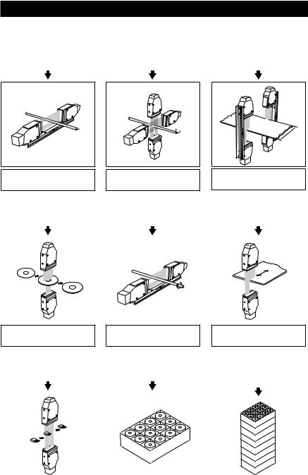
Optimum Measurement Methods
Refer to the following methods, and select the optimum measurement method according to the type of target.
Measurement of Outer Diameter |
|
Measurement of Average Outer |
|
Measurement of Sheet Width |
of a Round Bar or Wire |
|
Diameter of a Round Bar or Wire |
|
|
|
|
|

 D
D
Measurement of outer diameter and width (with single measuring head) (Page 3-2)
Y
 X
X
Measurement of outer diameter and width (with two measuring heads in X and Y directions) (Page 3-3)
L |
Measurement of outer diameter and width (with two measuring heads for larger objects) (Page 3-4)
Measurement of Inner |
|
Measurement of Outer Diameter |
|
Measuring Robot Movement |
||
Diameter of a Disc |
|
and Eccentricity of Roller |
|
and Positioning of LCD Plate |
||
|
|
|
|
|
|
|
|
|
|
|
|
|
|
|
|
|
|
|
|
|
|
|
|
|
|
|
|
Measurement of inner diameter and clearance (Page 3-5)
Measurement of outer diameter and eccentricity (Page 3-6)
Measurement of movement and positioning (Page 3-7)
Measurement of Connector |
|
Measurement of Size |
|
Calculation of Max., Min., |
|||
|
|
Average, and Standard Deviation |
|||||
Pins and IC Pins |
|
Uniformity |
|
||||
|
|
Values of Measured Data |
|||||
|
|
|
|
|
|
||
|
|
|
|
|
|
|
|
|
|
|
|
|
|
|
|
|
|
|
|
|
|
|
|
|
|
|
|
|
|
|
|
|
|
|
|
|
|
|
|
|
|
|
|
|
|
|
|
|
|
|
|
|
|
|
|
|
|
|
|
|
|
|
|
Measurement of pitch (Page 3-8) |
|
Group processing (Page 3-9) |
|
Statistical processing (Page 3-10) |
|
|
|
|
|
vi

Configuration of Manual
Chapter 1 Getting Started
Provides information on precautions and necessary preparations required.
Chapter 2 Basic Operation of LS-7600 Series
Provides information on the basic operation of the LS-7600 Series, panel keys, and remote control console.
Chapter 3 Easy Setting Guide
Provides information on targets and settings for typical applications respectively.
Chapter 4 Operation Control
Provides information on setting control items on the control panel while the LS-7600 Series is in measurement operation.
Chapter 5 Function Settings
Provides information on the overview of program settings and setting methods.
Chapter 6 Environment Settings
Provides information on basic operation settings.
Chapter 7 I/O Terminals
Provides information on the specifications of the I/O terminals and timing charts.
Chapter 8 RS-232C
Provides information on how to connect external devices and the communications function to operate the LS-7600 Series through the external devices.
Chapter 9 Specifications
Provides the specifications, characteristics, and external dimensions of the LS-7600 Series.
Chapter 10 Troubleshooting
Provides information on troubleshooting and error messages.
Appendix
Provides a list of options and the index of the manual.
1
2
3
4
5
6
7
8
9
10
Appendix
vii

Contents
Safety Precautions .............................................................................................................. |
i |
Precautions for CE Markings ........................................................................................... |
iv |
About this Manual .............................................................................................................. |
v |
Page Configuration and Symbols .................................................................................... |
v |
Definition of Terms .......................................................................................................... |
v |
Optimum Measurement Methods .................................................................................... |
vi |
Configuration of Manual .................................................................................................. |
vii |
Contents ........................................................................................................................... |
viii |
Chapter 1 Getting Started
Outline and Features of LS-7600 Series ....................................................................... |
1-2 |
System Applications ....................................................................................................... |
1-4 |
Package Contents ........................................................................................................... |
1-5 |
LS-7601 ....................................................................................................................... |
1-5 |
LS-7010M .................................................................................................................... |
1-5 |
LS-7030M .................................................................................................................... |
1-5 |
LS-7070M .................................................................................................................... |
1-6 |
LS-C A ..................................................................................................................... |
1-6 |
LS-C AM .................................................................................................................. |
1-6 |
LS-S11 ......................................................................................................................... |
1-7 |
Functions and Nomenclature ......................................................................................... |
1-8 |
Controller ..................................................................................................................... |
1-8 |
Measuring Head ........................................................................................................... |
1-9 |
Mounting and Connection ............................................................................................ |
1-11 |
Mounting the Measuring Head ................................................................................... |
1-11 |
Mounting the Controller .............................................................................................. |
1-13 |
Connection ................................................................................................................. |
1-17 |
Turning AC Power Supply Stand On and Off .............................................................. |
1-19 |
Adjustments to LCD Monitor ....................................................................................... |
1-20 |
Measurement and Setting Overview ........................................................................... |
1-21 |
Resetting to Initial Status ............................................................................................. |
1-22 |
Chapter 2 Basic Operation of LS-7600 Series
Control Panel Functions and Nomenclature ................................................................ |
2-2 |
Panel Key Functions .................................................................................................... |
2-2 |
Remote Control Console Functions and Nomenclature ............................................... |
2-3 |
Names and Functions of the LCD Monitor Screen ...................................................... |
2-4 |
Chapter 3 Easy Setting Guide
Measurement of Outer Diameter and Width (with Single Measuring Head) |
.............. 3-2 |
Measurement of Outer Diameter and Width (with Two Measuring Heads) ................. |
3-3 |
Measurement of Outer Diameter and Width |
|
(with Two Measuring Heads for Larger Objects) .......................................................... |
3-4 |
Measurement of Inner Diameter and Clearance ........................................................... |
3-5 |
Measurement of Outer Diameter and Eccentricity ....................................................... |
3-6 |
Measurement of Movement and Positioning ................................................................ |
3-7 |
Measurement of Pitch ..................................................................................................... |
3-8 |
Group Processing ........................................................................................................... |
3-9 |
Statistical Processing ................................................................................................... |
3-10 |
Chapter 4 Operation Control
Switching Display Screen .............................................................................................. |
4-2 |
Measured Value Display .............................................................................................. |
4-2 |
NG RECORD Display .................................................................................................. |
4-5 |
viii
Target Viewer Function ................................................................................................... |
4-7 |
Switching Cameras ...................................................................................................... |
4-8 |
Hold Function .................................................................................................................. |
4-9 |
Automatic Zero Function .............................................................................................. |
4-10 |
Key Lock Function ........................................................................................................ |
4-11 |
Program Changes ......................................................................................................... |
4-12 |
Chapter 5 Function Settings
Flow of Program Settings............................................................................................... |
5-2 |
Default Values and Possible Setting Ranges................................................................ |
5-4 |
Copying Program Setting Details and Initialization ..................................................... |
5-6 |
Setting Screen ................................................................................................................. |
5-7 |
Area Settings ................................................................................................................... |
5-9 |
Area Selection ............................................................................................................ |
5-10 |
Area Display ............................................................................................................... |
5-15 |
Focus Monitor ............................................................................................................ |
5-16 |
Area Check ................................................................................................................ |
5-17 |
Difference Check ........................................................................................................ |
5-18 |
Function Output Selection .......................................................................................... |
5-19 |
Change of Edge Detection Threshold ........................................................................ |
5-20 |
Calibration Settings ...................................................................................................... |
5-22 |
Calibration Type Selection .......................................................................................... |
5-24 |
Logic Calibration Settings .......................................................................................... |
5-24 |
Two-point Calibration Settings .................................................................................... |
5-26 |
One-point Calibration Settings ................................................................................... |
5-27 |
Initialization of Calibration .......................................................................................... |
5-28 |
Output Settings ............................................................................................................. |
5-29 |
Area Calculation ......................................................................................................... |
5-30 |
Number of Averaging Measurements......................................................................... |
5-31 |
Measuring Mode ........................................................................................................ |
5-33 |
Offset ......................................................................................................................... |
5-43 |
Analog Output Settings .............................................................................................. |
5-44 |
Comparator Output Setting ........................................................................................ |
5-47 |
Tolerance (LIMIT) Settings ........................................................................................... |
5-49 |
Limit Range ................................................................................................................ |
5-50 |
Limit Settings ............................................................................................................. |
5-51 |
Hold Value Elimination ............................................................................................... |
5-52 |
Option Settings ............................................................................................................. |
5-55 |
Tolerance Mode (LIMITS)........................................................................................... |
5-56 |
Timing Mode .............................................................................................................. |
5-56 |
Display Unit ................................................................................................................ |
5-57 |
Minimum Display Unit ................................................................................................ |
5-58 |
I/O Mode .................................................................................................................... |
5-59 |
Units, Default Minimum Values, and Setting Ranges ................................................. |
5-60 |
Graph TIME ................................................................................................................ |
5-62 |
Statistical Processing ................................................................................................. |
5-62 |
Group Processing ...................................................................................................... |
5-63 |
Application Function ................................................................................................... |
5-64 |
Group Processing ......................................................................................................... |
5-65 |
Statistical Processing ................................................................................................... |
5-66 |
Application Function .................................................................................................... |
5-68 |
Drill Function .............................................................................................................. |
5-68 |
Dual Head Function ................................................................................................... |
5-70 |
ix

Chapter 6 Environment Settings
Possible Environment Settings...................................................................................... |
6-2 |
Default Settings ............................................................................................................ |
6-2 |
Changing Environment Settings .................................................................................. |
6-4 |
Details of Environment Settings .................................................................................... |
6-5 |
Program ....................................................................................................................... |
6-5 |
RS-232C ...................................................................................................................... |
6-7 |
Head ............................................................................................................................ |
6-9 |
Buzzer ........................................................................................................................ |
6-12 |
Key Lock .................................................................................................................... |
6-13 |
Display Language ...................................................................................................... |
6-13 |
LCD Monitor Backlight ............................................................................................... |
6-14 |
Date and Time ............................................................................................................ |
6-14 |
Chapter 7 I/O Terminals
Nomenclature and Functions of I/O Terminals |
............................................................. 7-2 |
Terminal Block .............................................................................................................. |
7-2 |
Connector I/O ............................................................................................................... |
7-4 |
VIDEO Output .............................................................................................................. |
7-7 |
Functions ..................................................................................................................... |
7-7 |
Electrical Specifications ............................................................................................... |
7-9 |
Timing Chart .................................................................................................................. |
7-11 |
Chapter 8 RS-232C
Specifications .................................................................................................................. |
8-2 |
Communication using Serial Commands ..................................................................... |
8-4 |
Connecting to a PC/PLC Link Unit ............................................................................... |
8-4 |
Connecting to KV Series .............................................................................................. |
8-5 |
Outline of Command Formats ...................................................................................... |
8-6 |
Measurement Serial Commands ................................................................................. |
8-7 |
Setup Serial Commands ............................................................................................ |
8-14 |
Serial Commands to Check the LS Settings .............................................................. |
8-22 |
Batch Commands ...................................................................................................... |
8-23 |
Timing Chart ............................................................................................................... |
8-24 |
ASCII Table ................................................................................................................ |
8-25 |
Communication using an External Synchronous Trigger ......................................... |
8-26 |
Command List ............................................................................................................... |
8-32 |
Chapter 9 Specifications
Specifications .................................................................................................................. |
9-2 |
Controller ..................................................................................................................... |
9-2 |
Measuring Head ........................................................................................................... |
9-3 |
Optional Accessories ................................................................................................... |
9-3 |
Characteristics ................................................................................................................ |
9-4 |
Measurement Range and Accuracy ............................................................................. |
9-4 |
Temperature Characteristics ........................................................................................ |
9-5 |
Response Delay Time .................................................................................................. |
9-6 |
Focus Characteristics................................................................................................... |
9-6 |
Mode Specifications ....................................................................................................... |
9-7 |
External Dimensions....................................................................................................... |
9-8 |
Chapter 10 Troubleshooting
Troubleshooting Guide ................................................................................................. |
10-2 |
Error Messages ............................................................................................................. |
10-6 |
x

Appendix
List of Optional Accessories ........................................................................... |
Appendix-2 |
Setting Record Sheet ....................................................................................... |
Appendix-3 |
Environment Setting Record Sheet ................................................................ |
Appendix-5 |
Index ................................................................................................................. |
Appendix-6 |
xi

MEMO
xii

Chapter 1
Getting Started
This section provides information on the configuration of the LS-7600 Series, precautions, and necessary preparations required before operating the LS-7600 Series. Familiarize yourself with this section before using the LS-7600 Series.
Outline and Features of LS-7600 Series .............................. |
1-2 |
System Applications ............................................................. |
1-4 |
Package Contents ................................................................ |
1-5 |
Functions and Nomenclature ............................................... |
1-8 |
Mounting and Connection .................................................. |
1-11 |
Turning AC Power Supply Stand On and Off ..................... |
1-19 |
Adjustments to LCD Monitor .............................................. |
1-20 |
Measurement and Setting Overview .................................. |
1-21 |
Resetting to Initial Status ................................................... |
1-22 |
1-1

Chapter 1 Getting Started
Outline and Features of LS-7600 Series
The LS-7600 Series is a high-speed, high-accuracy digital micrometer used for the dimen- 1 sional measurement of objects without coming into contact with the objects. It is such a
versatile model that it has a wide range of applications including in-line measurement and offline measurement.
■ Special Features
High-speed Sampling of 2400 Times per Second
Ensures high-speed sampling that is twice as fast as the sampling speed of conventional models. The continuous measurement of extruded products and the in-line measurement of moving workpieces are possible.
Repeat Accuracy of ±0.15μm
Incorporates the latest optical system, thus ensuring excellent repeat accuracy that is twice as high as the accuracy of conventional models, thus supporting the manufacture of high-precision products.
Connecting Two Measuring Heads for two-channel Simultaneous Measurement
Two measuring heads can be used in combination for the simultaneous measurement of two targets.
Stable Detection of Transparent Objects with Threshold Change
The threshold change function supported by the DE processor makes it possible to detect transparent objects stably.
Incorporates a Target Viewer Function for Measurement Point Monitoring
Incorporates a CMOS image sensor to monitor targets, thus making it possible to check measurement points no matter how complicated in shape the targets are.
Easy-to-use Remote Control Console
A simple, interactive menu is used on the handheld remote control console for ease of operation.
A Variety of Inspection Functions
Incorporates a group comparison function and statistical processing function.
1-2
Chapter 1 Getting Started
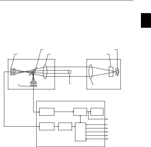
■ Principle of Measurement
The high-intensity GaN green LED radiates light, which will be changed into uniform parallel light through the special diffusion unit and collimator lens and emitted to the
target in the measuring range. Then the shadow image of the target will appear on the 1 HL-CCD (high-speed linear CCD) through the telecentric optical system. The output
incident signal of the HL-CCD will be processed by the DE (digital edge-detection) processor in the controller and CPU. As a result, the dimensions of the target will be displayed and output.
HL-CCD for |
Beam splitter |
High-intensity GaN green LED |
|
Telecentric optical |
|
||
measurement use |
Special diffusion unit |
||
system |
|||
|
|
CMOS image |
|
|
sensor |
Target |
Collimator lens |
|
||
Receiver |
|
Transmitter |
A/D |
Frame |
TFT LCD |
conversion |
memory |
monitor |
|
|
Video output |
A/D |
DE |
Control input |
conversion |
processor |
Control output |
|
CPU |
BCD output |
|
|
Analog output |
|
|
RS-232C interface |
|
Controller |
|
1-3
Chapter 1 Getting Started
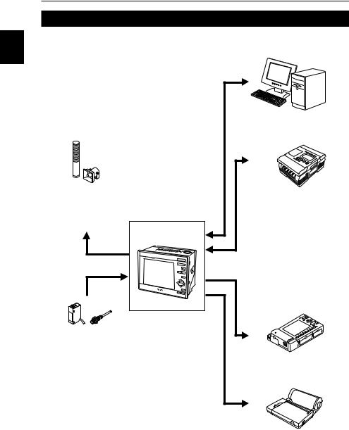
System Applications
The LS-7600 Series has a wide range of applications when used in combination with 1 commercially available peripheral devices.
Indicator Light and Buzzer
Alarms are generated according to the output of
discrimination results.
LS-7601
PC
Control values or measuring values are retrieved over RS232C.
Programmable Logic Controller
Control output and measured values are retrieved and programs for measurement timing control are changed.
Photoelectric Sensor or Proximity Sensor
Timing input signals are sent whenever targets are detected.
Recorder
The results of measurements are recorded.
Printer
The results of measurements are printed.
1-4
Chapter 1 Getting Started
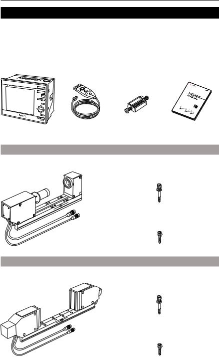
Package Contents
Check that nothing is missing from the LS-7600 Series package before use. |
1 |
||||
|
|
|
|
|
|
|
|
|
|
|
|
|
|
|
|
|
|
LS-7601 |
|
|
|
|
|
Controller |
Remote Control |
Four Panel Mounting |
LS-7600 Series |
|
|
|
Console |
Brackets |
User’s Manual |
|
|
LS-7010M
Measuring Head |
Allen-head bolt |
|
(Five, M3 x 45 with a washer) |
Allen-head bolt (Four, M4 x 20)
LS-7030M
Measuring Head |
Allen-head bolt |
|
(Six, M5 x 45 with a washer) |
Allen-head bolt (Four, M4 x 20)
1-5
Chapter 1 Getting Started
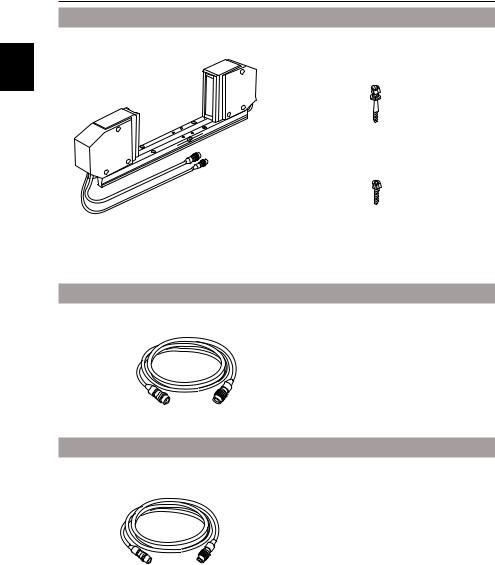
LS-7070M
Measuring Head |
Allen-head bolt |
1 |
(Six, M4 x 50 with a washer) |
|
Allen-head bolt (Four, M5 x 20)
LS-C A
Extension Cable (Cable between the controller and measuring head)
LS-C3A: 3-m cable
LS-C10A: 10-m cable
LS-C30A: 30-m cable
Up to two cables are connectable, provided that the total length of the cables does not exceed 40 m.
LS-C AM
Camera cable
LS-C3AM: 3-m cable
LS-C10AM: 10-m cable
LS-C30AM: 30-m cable
Up to two cables are connectable, provided that the total length of the cables does not exceed 40 m.
1-6
Chapter 1 Getting Started
LS-S11
Stand Unit |
Base Unit |
1
Screws (Four, M4 x 8)
Keyence ships each package with utmost care and attention. If there should be any improper or damaged product, contact your Keyence representative.
1-7
|
|
Chapter 1 Getting Started |
|
|
|
|
|
|
|
|
Functions and Nomenclature |
|
|
|
1 |
|
The following section provides information on the functions and nomenclature of the |
|
controller and measuring head. |
|
|
|
|
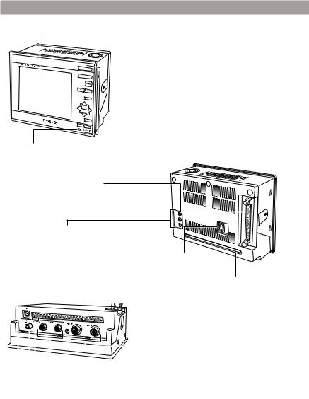
Controller
LCD Monitor
 Control Panel
(Page 2-2, Section 2 Basic Operation of LS-7600 Series)
Power Supply Indicator
The indicator is lit when power is supplied to the LCD monitor.
Connector I/O
Controller (Rear Side)
Used for signal I/O
(Page 7-2, Section 7 I/O Terminals)
LCD Monitor Adjustment |
|
|
|
Trimmer |
|
|
|
Used to make color, hue, or |
|
|
|
brightness adjustments to the |
Modular Connector |
|
|
LCD monitor. (Page 1-20) |
|
||
Used to connect the remote |
|
||
|
|
||
|
control console connector |
Terminal Block |
|
|
or RS-232C cable |
||
Controller (Bottom) |
connector. |
Used for signal I/O |
|
(Page 8-2, Section 8 |
(Page 7-2, Section 7 I/O |
||
|
|||
|
RS-232C) |
Terminals) |
|
|
|
|
|
|
|
|
|
|
Extension Connector |
|
|
|
|
|
|
|
|
|
|
|
|
|
|
|
|
|
|
|
|
|
|
|
|
|
|
|
|
|
|
|
|
|
|
|
|
|
|
|
|
|
|
|
|
|
|
|
|
|
|
|
|
|
|
|
|
|
|
|
|
|
|
|
Camera Connector |
Connect the cable |
|
|
|
|
|
|
|
|
|
between the controller |
||
|
|
|
|
|
|
|
|
|||
|
|
|
|
|
|
|
|
Connect the camera cable. |
||
|
|
|
|
|
|
|
|
and the measuring head. |
||
|
|
|
|
|
Power Input Terminals (24 VDC) |
|
|
|||
|
|
|
|
|
|
|
|
|||
|
|
|
|
|
|
|
|
|||
|
|
|
|
|
Provide 24 VDC power supply. |
|
|
|
||
|
|
|
|
|
|
|
|
|
|
Video Output |
|
|
|
|
|
|
|
|
|
|
|
DC IN |
|
|
Connector |
|||||||
|
|
Connect the monitor |
||||||||
Connect the LS-S11 AC Power Supply |
|
|
||||||||
|
|
cable. |
||||||||
Cable. |
|
|
||||||||
|
|
|
||||||||
1-8
Chapter 1 Getting Started
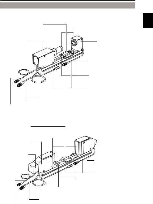
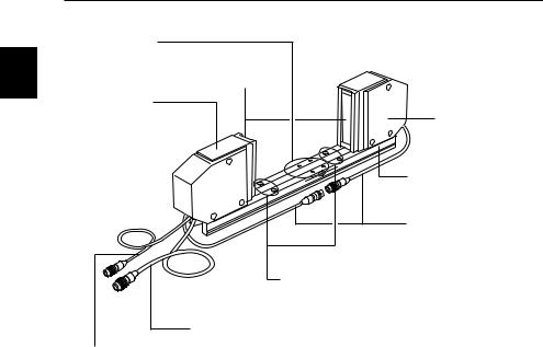
Measuring Head
LS-7010M |
|
1 |
Multi-purpose |
|
|
Mounting Holes |
Cover Glass |
|
A fixture for targets can |
|
|
be attached. |
|
|
Receiver (R Head) |
|
Transmitter (T Head) |
Receives light from |
|
Emits light for |
the transmitter. |
|
measurement. |
|
|
TR Base |
|
|
Used to mount the |
|
|
transmitter and receiver. |
|
|
TR Cables |
|
|
Used to connect the transmitter |
|
|
Mounting Holes |
|
|
Used to mount the |
|
|
measuring head. |
Extension Cable |
|
|
Connected to the controller. |
||
Camera Cable |
|
|
Connected to the controller. |
|
|
LS-7030M |
|
|
Multi-purpose |
|
|
Mounting Holes |
|
|
A fixture for targets can |
|
|
be attached. |
Cover Glass |
|
Receiver (R Head) |
|
|
Receives light from |
|
Transmitter (T Head) |
the transmitter. |
|
|
|
Emits light for |
|
|
|
|
Camera Unit |
|
measurement. |
|
|
|
|
|
TR Base |
|
|
Used to mount the |
|
|
transmitter and receiver. |
|
|
TR Cables |
|
|
Used to connect the |
|
|
transmitter and receiver. |
Mounting holes
Used to mount the measuring head.
Extension Cable
Connected to the controller.
Camera Cable
Connected to the controller.
1-9
|
Chapter 1 |
Getting Started |
|
|
LS-7070M |
|
|
|
Multi-purpose |
|
|
1 |
Mounting Holes |
|
|
A fixture for targets can |
|
||
be attached. |
|
||
|
Cover Glass |
|
|
|
Receiver (R Head) |
|
|
|
Receives light from |
Transmitter (T Head) |
|
|
the transmitter. |
||
|
Emits light for |
||
|
|
|
|
|
|
|
measurement. |
|
|
|
TR Base |
|
|
|
Used to mount the |
|
|
|
transmitter and receiver. |
|
|
|
TR Cables |
|
|
|
Used to connect the |
|
|
|
transmitter and receiver. |
|
|
|
Mounting holes |
|
|
|
Used to mount the measuring head. |
|
|
Extension Cable |
|
|
|
Connected to the controller. |
|
|
Camera Cable |
|
|
|
Connected to the controller. |
|
|
1-10
Chapter 1 Getting Started
Mounting and Connection
Mount the measuring head and the controller, and connect them with the cables. |
1 |
|
■ Mounting the Measuring Head
The measuring head can be mounted with or without the TR base employed, according to the type of targets and operating environment.
The following section provides information on how to mount the measuring head with or without the TR base employed, along with mounting conditions required.
■ Mounting the Controller
Mount the controller to panels, such as control or operation panels, or to the LS-S11 AC Power Supply Stand. The LS-S11 Power Supply Stand is sold separately.
■ Connection
After the measuring head and the controller are mounted, connect them with the cables.
Mounting the Measuring Head
■ Mounting Restrictions
The transmitter and receiver must abide by the following restrictions when the measuring head is mounted.
Vertical Position Mismatching
Receiver |
Transmitter |
|
±1 mm max. |
Receiver |
Transmitter |
|
±1 mm max. |
The values are the same for
LS-7010M, LS-7030M, and
LS-7070M.
Angle Mismatching
Receiver |
Transmitter |
|
±0.25° max |
Receiver |
Transmitter |
|
±0.25° max |
Receiver |
Transmitter |
|
±0.25° max |
Receiver |
Transmitter |
|
±0.25° max |
1-11
Chapter 1 Getting Started
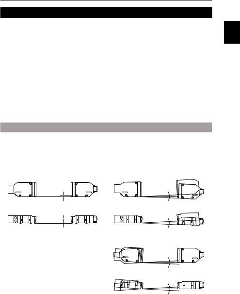
■ With TR Base
The transmitter and receiver are mounted to the TR base at the time of shipment. This section provides how to install the transmitter and receiver (LS-7030M in this case) that
1 are mounted on the TR base. LS-7010M and LS-7070M can also be installed in the same way.
Use the four, M4x20 Allen-head bolts, which are provided with the package, to mount the TR base. To mount the TR base with the bolts on the surface of the TR base, use the mounting holes on the surface.
To mount the TR base with the bolts on the back of the TR base, use the 10-mm-deep M4 (10-mm-deep M5 for LS-7070M) mounting holes on the back.
■ Without TR Base
Take the following steps to use the transmitter and receiver (LS-7030M in this case) after dismounting them from the TR base. LS-7010M and LS-7070M can also be used in the same way.
1 Loosen the bolts on the back of the TR base and remove the measuring head.
2 Mount the measuring head.
Use the side mounting holes on the transmitter and receiver as shown in the illustration. Mount them with the bolts provided with the package.
1-12
Chapter 1 Getting Started
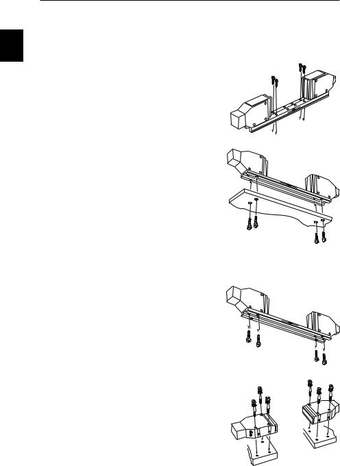
Use the 5-mm-deep M4 bottom mounting holes of the transmitter and receiver as shown in the illustration.
■When Using the Dual Head Function
When using the dual head function, mount the two measuring heads so that their top sides face each other.
1
Top
Mounting the Controller
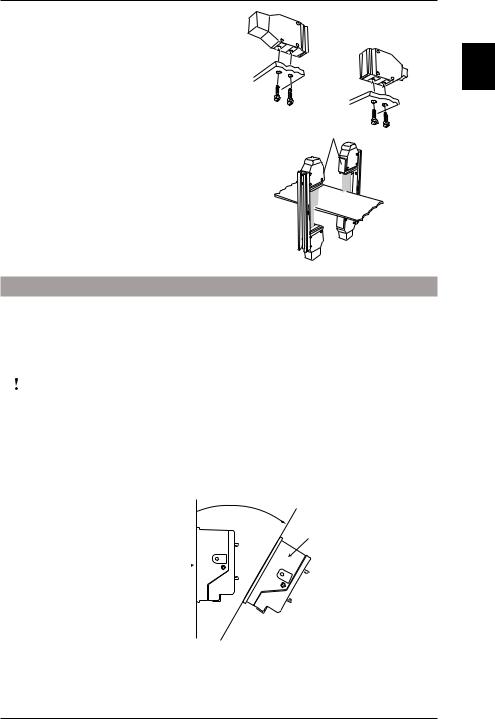
■ Mounting Restrictions
Be aware of the following items when mounting the controller.
|
CAUTION |
• Do not install the controller upside down. |
|||
|
• Do not block the ventilation louver. Otherwise, the interior heat |
||||
|
|
may cause the controller to malfunction. |
|||
|
|
|
|
|
|
Note: |
• For the maintenance, operability, and ventilation of the LS-7600 |
||||
|
|
Series, separate the controller as far as possible from periph- |
|||
|
|
eral structures or parts. |
|||
|
|
• The mounting angle must abide by the following restrictions. |
|||
|
|
|
|
|
30˚ |
|
|
Display |
|
|
Side |
|
|
|
|
||
|
|
|
|
|
|
|
|
|
|
||
|
|
panel |
|
||
|
|
|
|
|
|
•Check that the controller will not be exposed to the heat radiation of peripheral devices.
•Separate the controller as much as possible from devices with arc generation, such as electromagnetic switches or non-fuse breakers.
1-13
Chapter 1 Getting Started
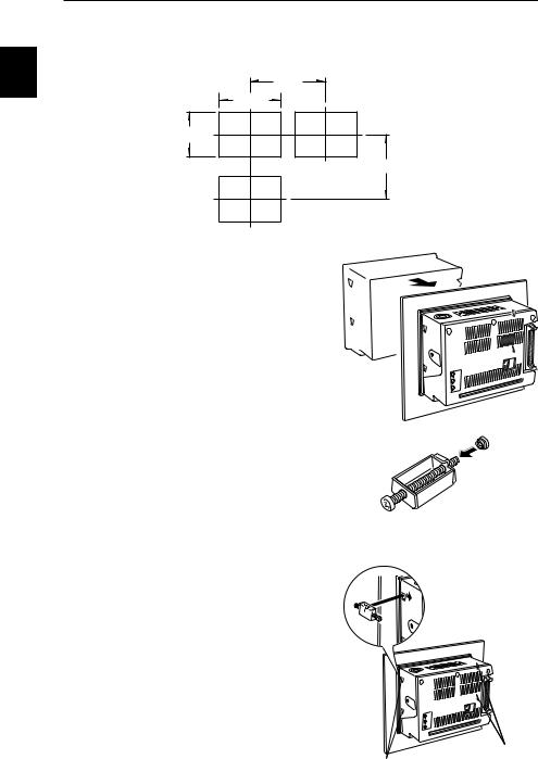
■ Mounting to Panel
The controller can be mounted to control panels with the mounting brackets provided with the package. Arrange the following panel mounting dimensions.
1
207
169 +10
124 +10
200
Unit: mm
1 Mount the controller from the front side of the panel.
2 Attach resin caps to the mounting brackets.
3 Insert the mounting brackets to the four mounting holes on the side of the controller respectively.
Mounting holes
Mounting holes
1-14
Chapter 1 Getting Started
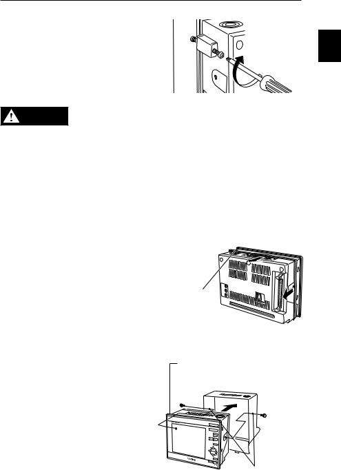
4 Secure the mounting brackets with a Phillips screwdriver.
1
• Tighten the mounting screws to a maximum torque of 0.4 Nm. CAUTION Do not tighten up the mounting screws excessively, otherwise
the panel or controller casing may be deformed.
•Do not remove the gasket, otherwise the controller will not satisfy IP64 conditions.
■Mounting to AC Power Supply Stand
The following section provides information on how to mount the controller to the AC power supply stand (sold separately). The AC power supply stand consists of a stand unit and base unit. Mount the controller to the stand unit first. Connect the power supply cable, extension cable (i.e., the cable between the controller and measuring head), and camera cable. Then mount them to the base unit.
1 Remove the gasket around the controller.
Gasket
2 Mount the controller to the stand.
Use the two screws provided with the package and secure the controller on the side.
The stand must be located on the groove from which the gasket was removed.
Secure these portions with screws.
1-15

Chapter 1 Getting Started
3 Connect the cable between the controller and measuring head.
If only a single measuring head is used, 1 connect the cable to the HEAD1 connec-
tor.
Cable between controller and measuring head
4 Connect the camera cable to the controller.
If only a single measuring head is used, connect the cable to the CAMERA1 connector.
Camera cable
5 Connect the power supply cable of the AC power supply stand to the controller.
6 Mount the stand unit to the base unit.
Mount the stand unit with the two screws provided with the package.
(2) Lean the stand unit in the direction indicated by the arrow. Pay utmost attention so that the connected cable will not be caught by the stand unit.
(1) Lean the stand unit in the front |
(3) Secure these portions |
direction and insert the tab. |
with screws. |
1-16
Loading...