


 Loading...
96M11665
Ultra-small Digital Laser Sensor
LV-S Series
Instruction Manual
Safety Information for LV-S series
Warning |
• This product is just intended to detect the object(s). Do not use this |
|
product for the purpose to protect a human body or a part of human |
||
|
||
|
body. |
|
|
• This product is not intended for use as explosion-proof product. Do |
|
|
not use this product in hazardous location and/or potentially explosive |
|
|
atmosphere. |
|
|
|
Safety precautions on laser products
Warning |
• Use of controls or adjustments or performance of procedures other |
|
than those specified herein may result in hazardous radiation expo- |
||
|
||
|
sure. |
|
|
• This product employs a semiconductor laser for its light source. |
|
|
• Follow the instructions mentioned in this manual. Otherwise, injury to |
|
|
the human body (eyes and skin) may result. |
|
|
Precautions on class 1 laser products |
|
|
• Do not disassemble this product. Laser emission from this product |
|
|
is not automatically stopped when it is disassembled. |
|
|
• Do not stare into the beam. |
|
|
|
Sensor head |
LV-S31/S41/S41L/S61/S71/S72 |
|
|
Wavelength |
655 nm |
|
|
Output |
290 μW |
|
|
FDA(CDRH) Part 1040.10* |
Class 1 Laser Product |
|
|
IEC 60825-1 |
Class 1 Laser Product |
|
|
*The classification is implemented based on IEC60825-1 following the requirements of Laser Notice No.50 of FDA (CDRH).
Safety Measures for the Laser
■ Laser emission stop input
The laser emission can be stopped by selecting the “Laser emission stop” signal (20 ms or more) from the input functions and inputting it externally. The emission stops while the signal is being input. The laser beam is emitted in 20 ms after the signal input is canceled. The control output functions according to the received light intensity even while laser emission stop is input.
Note
When the power is turned on, even when the laser emission stop signal is input, the laser is emitted for about 60 ms for self-diagnostic purpose.
Accessories
■ Amplifier
Mounting bracket: 1 |
End unit: 2 |
Instruction Manual: 1 |
Supplied with LV-11SA (P) Supplied with LV-12SA (P)
■ LV-S31 dedicated accessories |
■ LV-S41/S41L dedicated accessories |
Mounting bracket: 1 |
Mounting bracket: 1 |
Plate nut: 1 |
|
M3 x 15 screw: 2 |
|
Adjustment screwdriver: 1 |
|
■ LV-S61 dedicated accessories
Mounting bracket: 1
Plate nut: 1
M2 x 12 screw: 2
Reflector (R-6): 1
■ LV-S71/S72 dedicated accessories
Mounting bracket: 2 Nut: 4 |
Beam axis adjustment cap: 1 |
Facing ring: 2
Washer: 2
φ30
Identifying Part Names
Amplifier
■ LV-12SA (P)
Hold lock bar |
Output indicator lamp |
(for control output 1) |
Output indicator lamp |
(for control output 2) |
SET button |
Digital monitor |
Manual button |
Channel selection switch |
(display settings) |
Connector protection |
cover |
Extension connector |
MODE button |
Dust cover |
■ LV-11SA (P)
Sensor head
■ LV-S31
Operation indicator (red) |
|
Transmitting section |
FAR indicator (red) |
F |
Receiving section |
J |
F |
|
JUST indicator (green) |
N |
N |
|
||
NEAR indicator (red) |
|
|
|
|
Adjustment trimmer |
■ LV-S41
 Operation indicator (red)
Receiving section Transmitting section
E LV-S-IM |
1 |
■ LV-S41L
Receiving section |
Transmitting section |
Operation indicator (red)
■ LV-S61
Reflector (accessory)
Operation indicator (red)
Transmitting section, 
Receiving section
■ LV-S71
Operation indicator (red) |
|
Transmitter |
Receiver |
|
Transmitting section |
Receiving section |
■ LV-S72
Operation indicator (red)
Receiver
Transmitter
Transmitting section |
Receiving section |
The operation indicator works in conjunction with the Output selected at the channel selection switch. (It does with Output1 in area detection mode.)
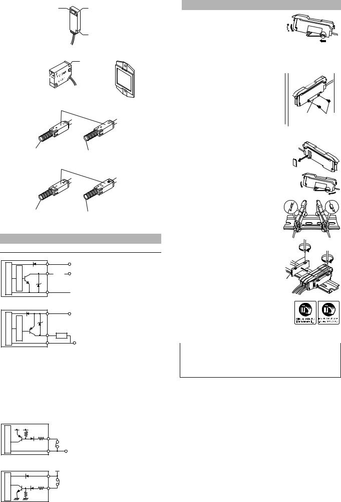
Input/Output Circuit Schematic
Output circuit
LV-11SA/12SA (NPN output type)
Brown *
circuitmainSensor |
circuitprotectionOvercurrent |
Blue * |
DC12-24V |
|
|
|
Black/white (control output 1/2) |
||
|
|
|
Load |
DC5-40V |
 0V
0V
* LV-11SA only
LV-11SAP/12SAP (PNP output type)
Brown *
DC12-24V
Sensormain circuit |
Overcurrentprotection circuit |
|
Black/white (control output 1/2) |
|
Load |
|
Blue * |
|
0V |
* LV-11SAP only
The power of the expansion unit LV-12SA (P) is supplied by the Extension connector on the side of the main unit LV-11SA (P). The power wires (brown and blue) of the main unit and those of the expansion unit are unified inside by the connector.
■ |
Input circuit |
|
|
|
|
• |
Not to be used |
|
|
Select either one. |
|
|
|
||||
• |
Light emission stop input |
|
|
||
• |
External calibration input |
|
|
(switched by the amplifier |
|
|
|
||||
• |
Setting value bank selection input |
|
|
function selection) |
|
• |
Received light intensity shift input |
|
|
|
|
LV-11SA/12SA (NPN output type)
circuit |
DC3.3V |
|
|
|
|
main |
|
Pink (input) |
|
|
|
Sensor |
|
PLC etc. |
(Short-circuit current 1 mA max.) |
Blue * |
|
|
0V |
|
|
|
|
* LV-11SA only |
|
|
LV-11SAP/12SAP (PNP output type)
circuit |
Brown * |
DC12-24V |
|
|
|||
|
PLC etc. |
||
main |
|
||
Pink (input) |
|||
Sensor |
|||
(Short-circuit |
|||
|
current 2 mA max.) |
||
* LV-11SAP only
Mounting the Amplifier Unit
■ Mounting on a DIN rail
1) |
Align the claw at the bottom of the main body with the |
(3) |
|
DIN rail. While pushing the main body in the direction |
|
|
of the arrow 1, slant it in the direction of the arrow 2. |
(2) |
2) |
To dismount the sensor, raise the main body |
|
|
in the direction of the arrow 3 while pushing |
(1) |
|
the main body in the direction of the arrow 1. |
|
■Installation using the mounting bracket (accessory) (LV-11SA/11SAP only)
Mount the amplifier unit using the supplied mounting bracket as shown in the figure.
Mounting bracket M3 screw (OP-25431)
■ Connecting several amplifier units
Up to 16 expansion units LV-12SA can be installed to the main unit LV-11SA.
1 Remove the protection cover on the side of the main unit.
2 Install the amplifier one by one on the DIN rail.
(2)
(1)
3 Engage the two claws of the expansion unit with the recesses on the main unit
side until you hear a click sound.
4 Install the end units on both ends of the amplifier unit.
Fasten the screws on the top of the end units (at two positions on both end units) with the Philips screwdriver.
Two end units are supplied with an expansion unit. OP-26751
* The stickers on the right are provided. Attach the sticker on the place near the amplifier unit.
■ Removing the amplifier unit
1 |
Remove the end units. |
|||
2 |
Slide the expansion unit and remove it one by one. |
|||
|
|
|
|
|
|
|
|
• |
When installing additional expansion unit, be sure to use the DIN rail and the end units. |
|
Important |
|||
|
• |
Turn off the power when installing or removing the unit. |
||
•Do not remove the protective cover of the extension connector on the amplifier expansion unit that is added at the end.
•Do not remove the amplifier unit with all added units attached, from the DIN rail.
•Verify the operation ambient temperature after additional installation. (“Specifications” page 9)
2 |
E LV-S-IM |

Connecting the Sensor Head and the Amplifier Unit
■ How to connect the amplifier unit and the connector
1 Open the dust cover, and tilt the hold-lock lever.
2 Raise the hook, and insert the connector to the very end.
3 Lower the hook and hook the part shown in the figure, and then raise the hold-lock lever.
Note
When shortening the sensor head cable, follow the instructions given in the “Sensor Head Connector Assembly Manual” included with the sensor head.
Mounting and Adjusting the Sensor Head
LV-S31
■ Adjusting the trimmer (detection position)
The detection range can be selected as desired by adjusting the trimmer.
|
When detecting the target |
|
|
When detecting the target |
|
from a long distance, turn the |
|
|
from a short distance, turn the |
|
trimmer clockwise to adjust. |
|
|
trimmer counterclockwise to |
F |
F |
F |
F |
adjust. |
J |
|
J |
|
|
N |
N |
N |
N |
|
■ Adjusting the center of detection
1 Place the workpiece at the position you want to set as the center of detection.
2 Turn the trimmer until JUST indicator (2) illuminates in green.
When (1) illuminates, turn the trimmer clockwise until (2) illuminates.
(1)F F When (2) illuminates, the adjustment is
(2)J complete.
N N
(3)
When (3) illuminates, turn the trimmer counterclockwise until (2) illuminates.
Finer adjustment is possible by looking at the display on the amplifier (page 7).
■ Detecting a height difference
A stable detection is made possible by adjusting the trimmer so that the middle point of the height comes to the center of detection.
■ Movement directions of the workpiece
Movement direction
Detecting |
|
Detecting |
Detecting |
|
object |
Movement |
object |
object |
Movement |
|
direction |
|
|
direction |
LV-S41/S41L
Be sure to use the supplied mounting bracket.
1 Press the mounting bracket on the sensor head.
Be sure to hook the A portion of the mounting bracket on the B portion of the sensor head.
A
B
2 Install the sensor head on the flat surface with the M3 screws as shown in the following figure. (The M3 screw is not an accessory.)
LV-S71/S72
Mount the sensor head such that the letter “T” (on the transmitter) or “R” (on the receiver) faces upward. The side where the operation indicator illuminates should face upward.
Fixing nut
Limit the tightening Beam axis adjusting torque up to 1.2 Nm. screw
■ Adjusting the beam axis
The angle of the beam axis can be changed upward if the screw indicated by the arrow is tightened, and downward if loosened.
When you want to lower the beam axis |
When you want to raise the beam axis |
||||||||||||||
|
|
|
|
|
|
|
|
|
|
|
|
|
|
|
|
Adjust the spot to be emitted at the center on the receiver.
The adjustment is facilitated by attaching the beam-axis adjustment cap supplied with the sensor head to the tip of the receiver. Once the adjustment is complete, remove the beam-axis adjustment cap.
Beam axis adjustment cap (supplied with the LV-S71)
E LV-S-IM |
3 |
Loading...