


 Loading...
96M12004
Surface Scanning
Laser Confocal Displacement Meter
LT-9001 Series
User’s Manual

Introduction
This instruction manual describes the operation and functions of the Surface Scanning Laser Confocal Displacment Meter LT-9001 Series. To ensure safety, performance and the function of the LT-9001 Series, please read this manual carefully.
Keep this manual in a safe place for future reference. Be sure that this manual eventually goes to the person who operates this product.
Symbols
These symbols alert you the matters that should be followed to prevent human injury and/or product damage.
 DANGER
Failure to follow instructions may lead to death or serious injury.
 WARNING
Failure to follow instructions may lead to injury.
 CAUTION
Failure to follow instructions may lead to product damage.
Note
Provides additional information on proper operation.
Provides advanced and useful information for operation.
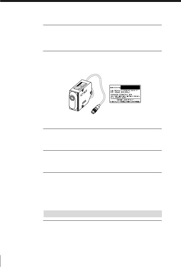
The contents of this manual pertain to operating the LT-9501/9010M or LT9501SO (5652)/LT-9030M.
If you are using the LT-9001/LT-9010 or LT-9001SO (5653)/LT-9030, skip the articles on the microscope function.
The profile mode cannot be used in the LT-9501SO (5652)/LT-9030 or LT9001SO (5653)LT-9030M.
Safety Precautions
General Precautions
•At startup and during operation, be sure to monitor the functions and performance of the LT-9001 Series.
•We recommend that you take substantial safety measures to avoid any damage in the event a problem occurs.
•Do not open or modify the LT-9001 Series or use it in any way other than described in the specifications.
•When the LT-9001 Series is used in combination with other devices, functions and performance may be degraded, depending on operating conditions and the surrounding environment.
•Do not use the LT-Series for the purpose of protecting the human body and lives.
•Do not change the temperature around the LT-Series including peripheral devices. Condensation may lead to malfunction.
Follow the safety precautions below to ensure operator safety.
•Apply the voltage correctly. Failure to do so may cause fire, electric shock or malfunction.
•Be sure to connect the earth ground terminal on the adaptor inlet of the controller. Failure to do so may cause electric shock and malfunction.
•Do not open or modify the unit. It may cause a fire or electric shock.
Handling the abnormalities
Turn off the power immediately in the following cases. Using the unit in an abnormal condition could cause fire, electric shock, or accident. Contact your nearest KEYENCE office for repair.
•If liquid including water, chemicals or debris enters the unit
•If the unit drops or the case is damaged.
•If abnormal smoke or smell occurs.
Follow the safety precautions below to ensure operator safety.
•Be sure to turn the power off when you plug/unplug the cable which connects the unit and the devices connected to the unit. Otherwise damage could result.
•Do not turn the power off while setting up the unit. Part or all of setting data may be lost.
•Do not block the vent holes on the unit and peripheral devices. Otherwise, excessive heat can build up and cause failure.
Installation environment
To use the LT-9001 Series correctly and safely, avoid installing it in the following locations:
•Locations that are humid, dusty or poorly ventilated.
•Locations with a high temperature such as a place exposed to direct sunlight
•Locations where there are flammable or corrosive gases.
•Locations where the unit may be directly subjected to vibration or impact.
•Location where water, oil or chemicals may splash onto the unit.
•Locations where the static electricity is easily generated.
E LT-9001-IM |
96M12004 |
1 |
Safety Precautions
Corrective action for noise
Do not install the LT-9001 Series near power sources or high tension cables, otherwise noise may cause the LT-9001 Series to malfunction. Take corrective action for noise by using noise filters, by separating these cables, by installing insulations to the controller and to the measuring unit.
Laser safety precautions
The LT-9001 is classified as a class1 laser product by IEC60825-1. (FDA class
IIa)
•Caution - use of controls or adjustments or performance of procedures other than those specified herein may result in hazardous radiation exposure.
•Do not stare into the laser beam directly for a long time.
•Do not disassemble the LT-9001 Series.
The Influence of ambient temperature
A change in ambient temperature may cause measurement fluctuations. Be sure to keep the temperature stabilized. When the ambient temperature changes 10 °C, it takes 60 minutes to equalize the distribution of the inside temperature.
Warming up
Before using the LT-9001 Series, wait approximately 60 minutes after the power is turned on. Otherwise, the measured value may gradually fluctuate because the circuit is not stable immediately after the power is turned on.
The Influence of dust or dirt
The measurement may fluctuate due to dirt, dust or fluid such as water or oil in the following cases:
•On the LT-9001 optics: Blow the dirt off with clean air. If dirt persists, wipe the glass surface gently using soft cloth soaked with alcohol.
•On the target surface: Blow the dirt off with clean air or wipe it off.
•Airborne: Build a protective enclosure with an air purge system around the measurement area.
Note
Influence of vibration
When the measurement target is vibrating, the measured value may fluctuate. In this case, increase the number or times the measurement value is averaged to achieve more accurate measurements.
2 |
E LT-9001-IM |

Measurement target
The measured value may fluctuate when the shapes or surfaces of targets vary. In this case, use a known target and perform appropriate correction with the calibration function.
Scan straightness
The scan orbit of the LT-9001 Series makes a slight arc. Therefore, the measured value may fluctuate when the target is slanted.
Handling
Do not wipe with a wet cloth, benzene, or thinner. Doing so could change the color or shape of the lens. If the lens has a lot of dirt on it, wipe it off with a cloth moistened with a mild detergent, then wipe with a soft dry cloth.
Effect of atmospheric motions
Slow atmospheric motions may affect the measurement resulting in the measured value fluctuation.
In such a case, take the following countermeasures.
•Enclose the measurement portion with the appropriate enclosure.
•Agitate the air between the measurement point and the workpiece strongly with the fan.
Best Management Practice for Perchlorate Materials - California only
When you sell, manufacture and/or waste the products containing perchlorate material in California, the following statement must appear on the exterior of all outer shipping packages and on consumer packages, based on California Code of Regulations.
"Perchlorate Material – special handling may apply, See www.dtsc.ca.gov/hazardouswaste/perchlorate."
Note: Alternative option is to indicate this statement on your MSDS or manual accompanying with each product.
This product includes a CR coin type cell containing perchlorate material. If you ship this product (or your product including this product) to California, you must ensure to comply with this regulation.
E LT-9001-IM |
3 |

Precaution on CE Marking
It is confirmed that the LT-9001 Series satisfies the requirement of the EU Directives when the following conditions are fulfilled. Therefore, users must fulfill the following conditions when the LT-9001 Series is going to be used in EU Member States.
Precautions
Precautions on EMC Directive
• Applicable standard (EMI) |
EN61326-1, Class A |
• Applicable standard (EMS) |
EN61326-1 |
•Wind the following ferrite core twice on the cable at the position within 50 mm from the analog output that is on the rear panel of the controller.
Model: ZCAT3035-1330 (Product of TDK)
•Wind the following ferrite core twice on the cable at the position within 200 mm from the VIDEO output that is on the rear panel of the controller.
Model: ZCAT2035-0930 (Product of TDK)
Precautions on Low Voltage Directive
• Applicable standard |
EN61010-1 |
|
|
EN60825-1 |
Laser Class 1 |
• Overvoltage category |
II |
|
• Pollution degree |
2 |
|
•The LT-9001 Series is classified as a class 1 laser product.
•When the LT-9001 Series is used in EU Member States, the power supply cable conforming to the relevant EU standards and obtaining the certification by a third-party certification organization, and its plug shape fitting to outlets of respective countries must be used.
•Because the LT-9001 Series is designed as class I equipment, be sure to connect the protective earthing terminal located in the inlet to the protective earthing conductor in the building when installing it.
•When replacing the fuse, be sure to use the fuse that satisfies the following
rating and is approved by certification organization based on the appropriate EU standard.
Fuse rating 250 V, 3.15 A, Time lag fuse
4 |
E LT-9001-IM |

Organization of this Manual
Chapter
1 |
|
Before Use |
|
|
|
|
|
Chapter |
|
Basic Operations |
|
|
|||
2 |
|
|
|
|
|
|
|
|
|
|
|
Chapter |
Operations and |
|
|
|
|||
3 |
|
Function Settings in |
|
|
the Displacement Mode |
|
|
|
|
|
|
Chapter |
Operations and |
|
|
|
|||
4 |
|
Function Settings |
|
|
in the Profile Mode |
|
|
|
|
|
|
Chapter |
Common |
|
|
|
|||
5 |
|
Operations and |
|
|
Function Settings |
|
|
|
|
|
|
Chapter |
Environment |
|
|
|
|||
6 |
|
|
|
|
Settings |
|
|
|
|
|
|
|
|
|
|
Chapter |
I/O Terminal |
|
|
|
|||
7 |
|
|
|
|
|
|
|
|
|
|
|
Chapter |
RS-232C |
|
|
|
|||
8 |
|
|
|
|
|
|
|
|
|
|
|
Chapter |
Specifications |
|
|
|
|||
9 |
|
|
|
|
|
|
|
|
|
||
Appendices |
|
Index |
|
|
|
|
|
Describes the cautions for use and the required preparation before use.
Describes how to use the remote control console and the basic operations of the LT-9001 Series.
Describes the operations and functions in the displacement mode.
Describes the operations and functions in the profile mode.
Describes operations and functions common to the displacement mode and the profile mode.
Describes the items for the basic settings and the setting procedures related to the overall unit that are required for operation.
Describes the specifications and timing chart of each I/O terminal.
Describes each function and setting method of the RS-232C interface.
Provides specifications, characteristics, and outer dimensions.
Describes the troubleshooting methods, contents of the error messages and optional products.
Chapter
1
Chapter
2
Chapter
3
Chapter
4
Chapter
5
Chapter
6
Chapter
7
Chapter
8
Chapter
9
Appendices
E LT-9001-IM |
5 |

Table of Contents
Safety Precautions...................................................... |
1 |
General Precautions............................................ |
1 |
WARNING............................................................ |
1 |
CAUTION............................................................. |
1 |
Note ..................................................................... |
3 |
Precaution on CE Marking.......................................... |
4 |
Precautions.......................................................... |
4 |
Organization of this Manual........................................ |
5 |
Chapter 1 Before Use |
|
Outline of the LT-9001 Series .................................. |
1-1 |
System Configuration .............................................. |
1-2 |
Checking the Package Contents............................. |
1-3 |
LT-9501 ............................................................ |
1-3 |
LT-9010M ......................................................... |
1-3 |
LT-C2/C10 ........................................................ |
1-3 |
Identifying Part Names and Functions ................... |
1-4 |
Controller.......................................................... |
1-4 |
Measuring Unit ................................................. |
1-5 |
Remote Control Console .................................. |
1-6 |
Mounting and Connecting Parts.............................. |
1-7 |
Mounting the Measuring Unit ........................... |
1-7 |
Installation of the Controller.............................. |
1-8 |
Connection ....................................................... |
1-8 |
Chapter 2 Basic Operations |
|
Outline of Basic Operations .................................... |
2-1 |
Displacement Mode and Profile Mode.................... |
2-2 |
Displacement Mode ......................................... |
2-2 |
Profile Mode ..................................................... |
2-2 |
Outline of Measurement and Settings .................... |
2-3 |
Run Mode......................................................... |
2-4 |
Program Mode ................................................. |
2-5 |
Program Function............................................. |
2-8 |
Flow of Measurement ....................................... |
2-9 |
Operations............................................................. |
2-10 |
How to Use the [ENTER] Button..................... |
2-10 |
Selecting an Item ........................................... |
2-11 |
Entering a Value ............................................. |
2-11 |
Selection Method of the Run Mode ....................... |
2-12 |
Operational Flow ............................................ |
2-12 |
Using the Displacement Mode.............................. |
2-13 |
Selecting the Displacement Mode ................ |
2-13 |
Adjusting the Distance Between the Measuring |
|
Unit and the Measurement Target ................. |
2-14 |
Setting the Scanning Width/interval .............. |
2-14 |
Setting the Light Intensity Level .................... |
2-15 |
Measuring the Displacement ........................ |
2-15 |
Using the Profile Mode .......................................... |
2-16 |
Selecting the Profile Mode ............................ |
2-16 |
Adjusting the Distance Between the Measuring |
|
Unit and the Measurement Target ................. |
2-17 |
Setting the Scanning Width/interval .............. |
2-17 |
Setting the Upper and Lower Limits Display..2-18 |
|
Setting the Area.............................................. |
2-18 |
Measuring the Level Differences ................... |
2-19 |
Basic Operations that Stabilize Measurement ..... |
2-20 |
Changing the Scanning Width and the |
|
FINE Mode ..................................................... |
2-20 |
Changing the Light Intensity Level................. |
2-20 |
Resetting the Device to the Factory Settings ........ |
2-22 |
Default Values and Settings Range (LT-9010 (M)).... |
2-23 |
Displacement Mode ....................................... |
2-23 |
Profile Mode ................................................... |
2-24 |
Default Values and Setting Range ................ |
2-25 |
Default Values and Settings Range (LT-9030 (M)).... |
2-26 |
Displacement Mode ....................................... |
2-26 |
Default Values and Setting Range ................ |
2-27 |
Chapter 3 Operations and Function
Settings in the Displacement
Mode
Outline of Displacement Mode................................ |
3-1 |
What is displacement mode?........................... |
3-1 |
Display Screens ...................................................... |
3-2 |
Identifying Part Names and Functions of Screens .. |
3-3 |
Measurement Screen ....................................... |
3-3 |
Light Intensity Screen....................................... |
3-4 |
Measurement Screen .............................................. |
3-5 |
Display of Measured Value .............................. |
3-5 |
6 |
E LT-9001-IM |

Display of the Trend Graph.............................. |
3-5 |
Light Intensity Screen.............................................. |
3-7 |
Display of Measured Values ............................ |
3-7 |
Display of Received Light Intensity Graph....... |
3-7 |
Setting the Light Intensity Level ....................... |
3-8 |
Setting the Measurement Target Surface ........ |
3-8 |
Pause Screen .......................................................... |
3-9 |
Setting the Pause Screen ................................ |
3-9 |
OUTPUT Settings .................................................. |
3-10 |
Functions of the OUTPUT Settings................. |
3-10 |
Basic Settings........................................................ |
3-15 |
SCAN.............................................................. |
3-15 |
DARK ALARM ................................................ |
3-17 |
MASK ............................................................. |
3-18 |
OPTIONAL Settings............................................... |
3-19 |
CORRECT (Auto slant correction) ............. |
3-19 |
Chapter 4 Operations and Function
Settings in the Profile Mode
Outline of Profile Mode ............................................ |
4-1 |
What is profile mode?....................................... |
4-1 |
Types of Screens..................................................... |
4-2 |
Identifying Part Names and Functions of Screens .. |
4-3 |
Measurement Screen ....................................... |
4-3 |
Light Intensity Screen....................................... |
4-4 |
Measurement Screen .............................................. |
4-5 |
Display of Measured Value .............................. |
4-5 |
Display of Profile Waveform ............................. |
4-6 |
Light Intensity Screen.............................................. |
4-8 |
Display of Measured Value .............................. |
4-8 |
Display of Received Light Intensity Graph....... |
4-8 |
Setting the Light Intensity Level ....................... |
4-8 |
Changing the Ranges of the Areas.................. |
4-9 |
Pause Screen ........................................................ |
4-10 |
Setting the Pause Screen............................... |
4-10 |
OUTPUT Settings .................................................. |
4-12 |
Functions of the OUTPUT Settings................. |
4-12 |
Basic Settings........................................................ |
4-13 |
AREA .............................................................. |
4-13 |
SCAN.............................................................. |
4-14 |
DARK ALARM ................................................ |
4-16 |
SMOOTH (Smoothing) ................................... |
4-17 |
OPTIONAL Settings............................................... |
4-18 |
CORRECT (Auto Slant Correction) ............ |
4-18 |
PROFILE OUT (Profile Output) ....................... |
4-19 |
Chapter 5 Common Operations and
Function Settings
Outline of Common Operations and |
|
Function Settings..................................................... |
5-1 |
Outline of Operations and Functions....................... |
5-2 |
Microscope Function............................................... |
5-2 |
Hold Function .......................................................... |
5-3 |
Auto-zero Function .................................................. |
5-4 |
Keylock Function ..................................................... |
5-5 |
Program Change ..................................................... |
5-6 |
OUTPUT Settings .................................................... |
5-7 |
LIMITS (Tolerance)........................................... |
5-7 |
OUTPUT (Output)............................................. |
5-8 |
CALIB (Calibration) ........................................ |
5-16 |
OPTIONAL Settings............................................... |
5-18 |
DISPLAY......................................................... |
5-18 |
I/O................................................................... |
5-20 |
GAIN (Sensitivity) ........................................... |
5-20 |
Chapter 6 Environment Settings
Setting up the Basic Settings for the Overall Unit ... |
6-1 |
Items to be Set in the Environment Setting ............. |
6-2 |
Environment Setting Items ............................... |
6-2 |
List of Default Values........................................ |
6-2 |
How to Set up Environment Settings ....................... |
6-4 |
How to Set up Environment Settings ............... |
6-4 |
RS-232C Interface............................................ |
6-5 |
Program............................................................ |
6-6 |
Beep Sound ..................................................... |
6-7 |
Interface Language.......................................... |
6-7 |
Coefficient ........................................................ |
6-7 |
Chapter 7 I/O Terminal
Controlling and Outputting from the I/O Terminal ...7-1
E LT-9001-IM |
7 |

Table of Contents
Identifying Names and Functions of |
|
the I/O Terminal ....................................................... |
7-2 |
Terminal Block.................................................. |
7-2 |
Control I/O ........................................................ |
7-3 |
VIDEO Output .................................................. |
7-5 |
Functions of the I/O Signals ............................. |
7-5 |
Electrical Specifications .................................. |
7-8 |
Timing Chart ............................................................ |
7-9 |
Normal Measurement |
|
(When Profile Output is OFF) ........................... |
7-9 |
When Profile Output is ON (LT-9010 (M) only).... |
7-11 |
Timing Details (LT-9010 (M)).......................... |
7-13 |
Timing Details (LT-9030 (M)).......................... |
7-14 |
Timing Details |
|
(Common to the LT-9001 Series) ................... |
7-15 |
Chapter 8 RS-232C
Connecting to External Devices via RS-232C ......... |
8-1 |
Specifications .......................................................... |
8-2 |
Pin Layout ........................................................ |
8-2 |
Communication Specifications......................... |
8-2 |
Connecting to External Devices....................... |
8-2 |
Outputting Measured Values and |
|
Changing Settings by Using Commands ............... |
8-3 |
Environment Settings Parameters .................... |
8-3 |
Outline of Command Format ............................ |
8-3 |
Measurement Control Command and |
|
Measurement Operation Command Formats... |
8-4 |
Command Details............................................. |
8-5 |
Change Parameter Command Format ............. |
8-8 |
Command Details............................................. |
8-9 |
Check Parameter Command Format ............. |
8-15 |
Timing Chart................................................... |
8-16 |
ASCII Code Table (Reference) ...................... |
8-16 |
Outputting Measured Values by Using External |
|
Synchronization ..................................................... |
8-17 |
Environment Settings Parameters .................. |
8-17 |
Output Method ............................................... |
8-17 |
Timing Chart................................................... |
8-18 |
Output format ................................................. |
8-18 |
Chapter 9 Specifications
Specifications of the LT-9001 Series....................... |
9-1 |
Specifications .......................................................... |
9-2 |
Specifications of the Controller ........................ |
9-2 |
Specifications of the Measuring Unit ............... |
9-3 |
Status Table ..................................................... |
9-4 |
Specifications of the cable between |
|
measuring unit and controller .......................... |
9-5 |
Response Delay Time .................................... |
9-6 |
Display Update Cycle ...................................... |
9-6 |
Outside Dimensions ......................................... |
9-7 |
Appendices
Troubleshooting ...................................................... |
A-2 |
Error Messages....................................................... |
A-4 |
Optional Product List .............................................. |
A-5 |
Parameter Memo..................................................... |
A-6 |
Displacement mode......................................... |
A-6 |
Profile mode..................................................... |
A-8 |
Environment Setting Parameter Memo ................. |
A-10 |
Index ..................................................................... |
A-11 |
8 |
E LT-9001-IM |
Chapter 1
Before Use
Outline of the LT-9001
Series
The LT-9001 Series is a double scan highaccuracy sensor that employs a lens drive and a tuning fork in the confocal displacement principle. The LT-9001 Series can measure not only a highly accurate displacement, but also the slanting degree, the thickness of transparent object and the shape.
This chapter describes the configuration of the LT-9001 Series, cautions and the required preparation before use.
System Configuration .............................................. |
1-2 |
Checking the Package Contents ............................. |
1-3 |
Identifying Part Names and Functions..................... |
1-4 |
Mounting and Connecting Parts .............................. |
1-7 |
Chapter
1
Use Before
E LT-9001-IM |
1-1 |
System Configuration
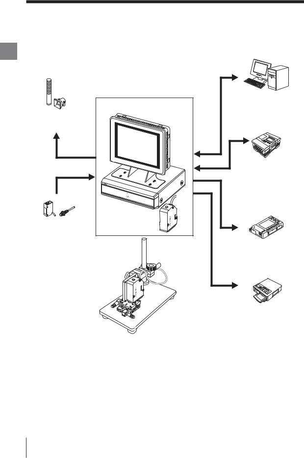
Chapter The LT-9001 Series can be used for various purposes in combination with commercially available devices.
1
Use Before
Indicator light/Buzzer
Produces an alarm sound by an output of the judgement.
Photoelectric/Proximity sensor
Transmits a signal to the TIMING input when the sensor detects a target.
LT-9001 Series |
Monitor |
-MN80 |
Controller |
LT-9501 |
Measuring unit |
LT-9010M |
PC
Enables control and import of the measured value from the RS232C or the parallel I/O board.
Programmable controller
Enables timing control of the measurement and the switching of program No. as well as the control output and the measured value import.
Recorder
Records the measurement result.
Stage system
The 2D shape or the 3D shape can be detected in combination with a manual or auto stage system.
Video printer
Prints the image of an LCD monitor.
1-2 |
E LT-9001-IM |
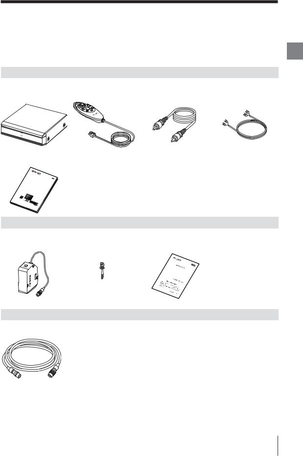
Checking the Package Contents
The LT-9001 Series consists of the following models. Check if the parts and equipment listed below are included in the package of the models you purchased before using the unit.
LT-9501
Controller |
Remote control console |
Monitor connecting cable |
Monitor power supply cable |
(LT-9501) ×1 |
(Cable length 3 m) ×1 |
(PIN-to-PIN cable: 2 m) ×1 |
(2 m) ×1 |
Chapter
1
Use Before
User's Manual (This manual) ×1
Double |
Scan |
|
|
|||
High- |
|
|
|
|||
LT- |
Accuracy |
Laser |
|
|||
|
|
|
Sensor |
|||
|
9001 |
|
|
|||
User’s |
|
|
|
Serie |
||
Manual |
|
|
||||
|
|
|
||||
LT-9010M
Measuring Unit |
Hexagon socket head bolt |
Cautions for export |
|||||||||||||
(LT-9010M) ×1 |
(M4 × 40 washer faced) ×3 |
(A6) ×1 |
|
|
|
||||||||||
|
|
|
This |
prod |
|
|
|
|
|
|
|
|
|
|
|
|
|
|
Japan. |
|
uct is |
su |
bject |
|
|
|
|
|
|
||
|
|
|
your |
|
When |
|
|
|
|
|
|
|
|
||
|
|
je |
ct to |
country, be |
need to |
to the |
|
|
|
|
|||||
|
|
|
|
|
|
you |
|
|
|
|
|
|
|||
|
|
not up |
the expo |
|
sure |
to c |
exportexport |
regulat |
|
|
|||||
|
|
take app on your ownrt regulationsheck if thisthis product |
ions |
in |
|||||||||||
|
|
by the |
ropriate |
|
respo |
|
within y |
product is |
from |
|
|||||
|
|
your coungovernmentaction for |
|
nsibility. If r |
|
our co |
untry |
sub- |
|
||||||
|
|
|
try. |
|
or respo |
gaining app |
equired, |
or |
|
||||||
|
|
|
|
|
|
|
|
nsible o |
roval for expplease |
|
|
||||
|
|
|
|
|
|
|
|
|
rganization |
ort |
|
|
|||
|
|
|
|
|
|
|
|
|
|
|
|
within |
|
|
|
LT-C2/C10
Cable between the controller and the measuring unit ×1
LT-C2: 2 m cable
LT-C10: 10 m cable
Up to three cables below the total length of 20 m can be connected.
*We have thoroughly inspected the package contents before shipment. However, in the event of defective or broken items, contact your nearest KEYENCE office (Address listed in the end of this manual).
*The contents included in the LT-9001/LT-9010 are the same as the ones in the LT-9501/LT-9010M respectively.
*The sensor head contained in the LT-9030M and LT-9030 is the LT-9030 and LT-9030, respectively. All of the other contents included in the LT-9030M or LT-9030 are the same as those included in the LT-9010M.
E LT-9001-IM |
1-3 |
Identifying Part Names and Functions
Chapter
1
Use Before
This section describes the names and functions of the controller, measuring
unit, and remote control console.
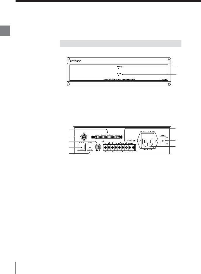
Controller
Front
1
2
1 Power LED
Lights up when the power is ON.
2 Laser LED
Lights up during laser emission.
Back |
|
2 |
6 |
1 |
8 |
5 |
|
3 |
7 |
|
|
4 |
|
1 |
Measuring unit connector |
|
The cable between the controller and the measuring unit is connected here. |
2 |
Connector terminals (Control I/O) |
Outputs binary data and tolerance judgment value, and switches the program No.
3 |
Remote control console connector |
|
The supplied remote control console is connected here. |
4 |
RS-232C connector |
|
The RS-232C communication cable is connected here. |
5 |
Video composite output terminal |
|
The external monitor is connected here. |
6 |
Terminal block |
Used for power supply, analog output, and input of control signal to the monitor (CA-MN80).
1-4 |
E LT-9001-IM |
7 AC power inlet
Supplies power to the LT-9001 Series.
8 Power switch
Turns on/off the power.
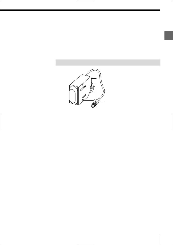
Measuring Unit
4


 2 1
2 1 
3
1 Sensor unit (Emitter/Receiver)
Emits and receives a laser beam for measurement. It is protected with a cover glass.
2 Mounting holes
The measuring unit is mounted with the supplied hexagon socket head bolt.
3 Connecting cable
The cable between the controller and the measuring unit can be connected to this cable, or the controller can be connected directly.
4 Laser emission LED
Lights up during laser emission.
Chapter
1
Use Before
E LT-9001-IM |
1-5 |
Identifying Part Names and Functions
Chapter
1
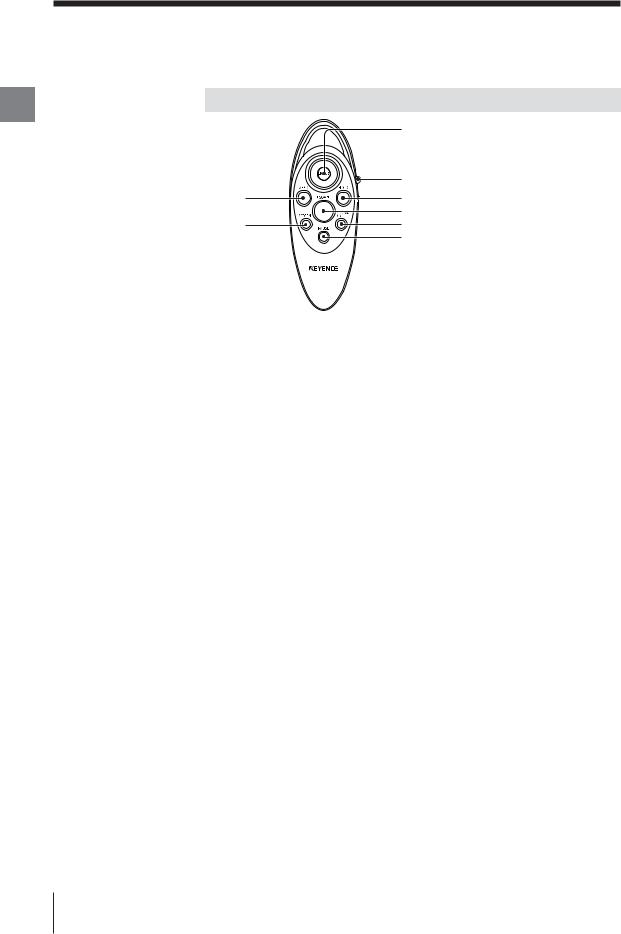
Remote Control Console
Use Before
|
1 |
|
2 |
8 |
3 |
|
4 |
7 |
5 |
|
6 |
1 [ENTER] button
Select the items by tilting the [ENTER] button up, down, right or left. Fix the selected item by pressing the button straight down.
 Refer to "How to Use the [ENTER] button" (page 2-10).
2
3
[PROG/RUN] switch
Switch the run/program modes by sliding down the switch. Each sliding movement switches the modes.
[HOLD] button
Press the [HOLD] button to retain the measured value. This button has the same function with the TIMING input terminal on the back of the controller.
 Refer to "Hold Function" (page 5-3).
4 [ESCAPE] button
Press the [ESCAPE] button to return to the previous display or operation during settings.
Press this button to exit or abort the setting item. This button has the same function with the RESET input terminal on the back of the controller in the run mode.
5
6
7
[PROGRAM No.] button
Press the [PROGRAM No.] button to switch the display to the program No. selection screen.
[PAUSE] button
Press the [PAUSE] button to stop updating the graph display while in the measurement screen, and to switch to the pause screen.
[SCREEN] button
During measurement: Press the [SCREEN] button to switch the measurement screen to the light intensity screen.
During setting: Press the [SCREEN] button to switch the selection status.
8 [ZERO] button
Press the [ZERO] button to use the Auto-zero function. This button has the same function with the ZERO input terminal on the back of the controller.
 Refer to "Auto-zero Function" (page 5-4).
1-6 |
E LT-9001-IM |
Mounting and Connecting Parts
This section describes how to mount the controller and the measuring unit.
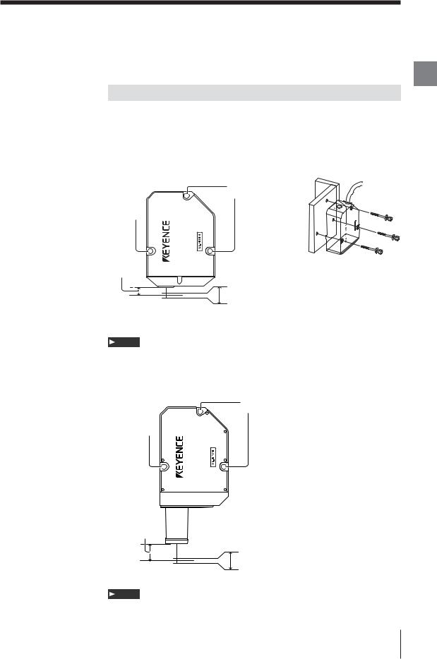
Mounting the Measuring Unit
Adjust the distance between the measuring unit and the measurement target and fix the measuring unit with screws in the three installation holes.
The measurement range is shown in the figure below.
• Measurement range |
• How to mount the unit |
■ LT-9010 (M) |
|
Installation hole
Installation hole
Reference distance
6mm
|
+0.3mm |
|
Reference |
Measurement range |
|
-0.3mm |
||
position |
||
|
0mm
Note
The reference distance may vary within the range of 0.5 mm according to the manufacturing variation of individual measuring units.
■ LT-9030 (M)
Installation hole
Installation hole
Reference distance
30mm
Reference |
+1.0mm |
Measurement range |
|
position |
-1.0mm |
0mm |
|
Note
The reference distance may vary within the range of 2.0 mm according to the manufacturing variation of individual measuring units.
Chapter
1
Use Before
E LT-9001-IM |
1-7 |
Chapter
1
Use Before
Mounting and Connecting Parts
Installation of the Controller
Use the controller on a level place.
Note
•Keep enough room around the controller for ventilation.
•When the temperature in the controlling system unit rise over 35 °C, decrease the ambient temperature no more than 35 °C by cooling it down with cool air or by make room around the system.
•Do not use the controller on other devices.
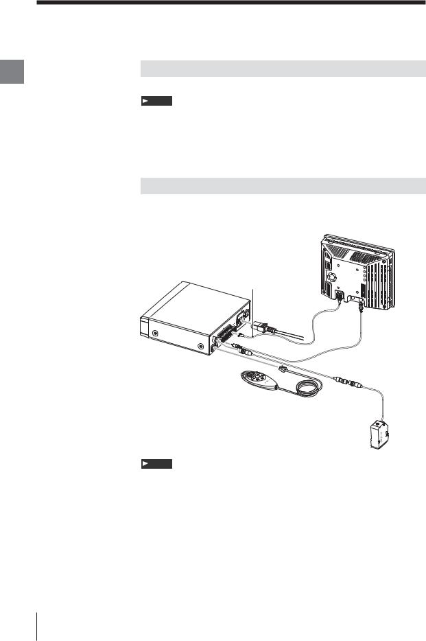
Connection
Connect the measuring unit, the controller, the remote control console, the
monitor and the power supply with cables.
|
Connecting to |
LT-9501 |
24 V DC terminal |
|
Monitor |
|
CA-MN80 |
AC cable |
|
|
Monitor connecting |
Power supply |
cable |
|
|
cable for the monitor |
|
|
Cable between the controller |
|
and the measuring unit |
Remote control |
|
console |
|
LT-9010M
Note
•Turn off the power supply of the controller before connecting/disconnecting cables. Failure to do so may cause malfunction.
•Eusure correct orientation of all connectors. Otherwise the pins may break and may lead to system breakdown.
•Before connecting the monitor power cable, ensure the correct polarity of the monitor power terminals. Failure to do so may cause malfunction.
•The 24 V DC terminal on the terminal block is a dedicated power supply unit to the monitor specified by KEYENCE only. This supply may not be used to power any additonal hardware.
1-8 |
E LT-9001-IM |

Chapter 2
Basic Operations
Outline of Basic
Operations
The LT-9001 Series performs settings concerning the measurement method or displayed information while in the program mode, and displays the measurement result value or graph while in the measurement mode.
You can also switch between displacement mode and profile mode depending on the target.
This chapter describes the outlines of program mode and run mode, and the procedures to operate the LT-9001 Series in displacement mode and profile mode using the remote control console.
Displacement Mode and Profile Mode..................... |
2-2 |
Outline of Measurement and Settings ..................... |
2-3 |
Operations ............................................................. |
2-10 |
Selection Method of the Run Mode ....................... |
2-12 |
Using the Displacement Mode............................... |
2-13 |
Using the Profile Mode .......................................... |
2-16 |
Basic Operations that Stabilize Measurement....... |
2-20 |
Resetting the Devices to the Factory Settings....... |
2-22 |
Default Value and Settings Range ........................ |
2-23 |
*All the measurement screens used in this User's Manual are those for the LT-9010(M).
Some screens are different when you are using the LT-9030(M).
Chapter
2
Operations Basic
E LT-9001-IM |
2-1 |
Displacement Mode and Profile Mode
Chapter
2
Operations Basic
You can select either displacement mode or profile mode in the LT-9010(M).
(Only displacement mode is available in the LT-9030(M).
|
Displacement Mode |
|
Profile Mode |
|||||||||||
The displacement mode enables you to measure a |
The profile mode enables you to measure the target shape |
|||||||||||||
targed in four ways such as displacement, |
by using the measured value of each scanned point. |
|||||||||||||
transparent object thickness, slant, and slant of the |
You can also measure the average value, maximum value, |
|||||||||||||
target by measuring the changes in the distance from |
minimum value, differential between the maximum and the |
|||||||||||||
the reference point. |
minimum value, and area by specifying two different areas |
|||||||||||||
|
|
|
|
|
|
on the target. |
|
|
|
|
|
|
|
|
|
|
|
|
|
|
|
|
|
|
|||||
|
|
|
|
|
|
|
|
|
|
|
|
|
|
|
|
|
|
|
|
|
|
|
|
|
|
|
|
|
|
Mesuring  unit
unit 


 Scanning width

 Scanning interval
Measurement Target
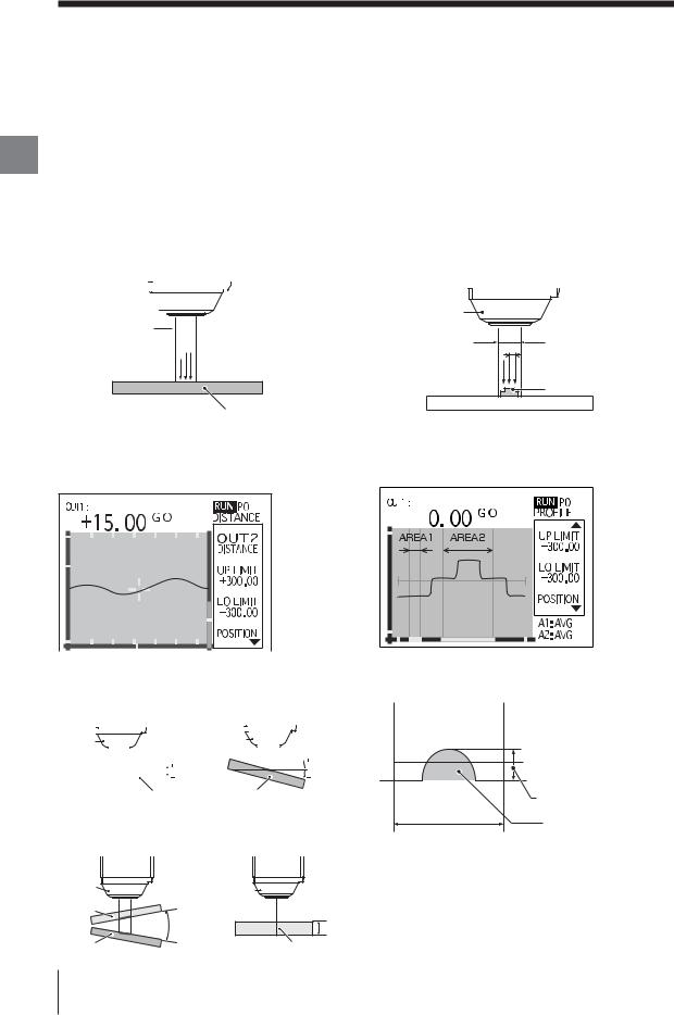
Example of the measurement screen in the
displacement mode
A change in the distance from the reference point can be measured.
DISTANCE |
SLANT (LT-9010 (M) only) |
The distance change from the The degree between the reference distance on the reference surface and the measurement target is measured. target surface is measured.
|
|
|
|
|
|
|
|
|
Distance |
|
|
|
|
|
|
|
|
|
|
||
Measuring |
|
|
|
|
change from |
Measuring |
|
|
|
|
Degree in relation |
||||||||||
|
|
|
|
|
|
|
|
|
|
|
|
|
|
|
|
|
|
|
|
to the reference |
|
unit |
|
|
|
|
the reference |
unit |
|
|
|
|
surface. |
||||||||||
|
|
|
|
|
|
|
|
|
|
|
|
||||||||||
|
|
|
|
|
|
|
|
|
point |
|
|
|
|
|
|
|
|
||||
|
|
|
|
|
|
|
|
|
|
|
|
|
|
|
|
|
|
|
|||
|
|
|
|
|
|
|
|
|
|
|
|
|
|
|
|
|
|
|
|
|
|
|
|
|
|
|
|
|
|
|
|
|
|
|
|
|
|
|
|
|
|
|
|
|
|
|
|
|
|
|
|
|
|
|
|
Measurement Target |
|||||||||
|
|
|
|
|
Measurement Target |
||||||||||||||||
SLANT (LT-9010 (M) only) |
THICK |
|
|
|
|
|
|
||||||||||||||
The relative degree between |
(Transparent object thickness) |
||||||||||||||||||||
the target and a transparent |
The thickness of a transparent |
||||||||||||||||||||
target is measured. |
object is measured. |
||||||||||||||||||||
Measuring |
Measuring |
||
unit |
|||
unit |
|
||
Transparent |
Thickness of the |
||
|
|||
object |
Relative |
transparent object |
|
|
|
||
|
slant |
|
|
Measurement |
|
Measurement Target |
|
Target |
|
(transparent object) |
|
Measuring |
|
unit |
|
Scanning |
|
width |
Scanning interval |
|
Measurement Target |
Example of the measurement screen in the profile
mode
The profile of a target can be displayed in a
waveform. |
Example of setting areas
The following features can be selected and measured within the specified Area 1 and Area 2.
|
MAX (maximum value) |
|
AVG (average value) |
|
MIN (minimum value) |
|
DIFF (differential value) |
Area setting range |
AREA (amount of space) |
|
2-2 |
E LT-9001-IM |

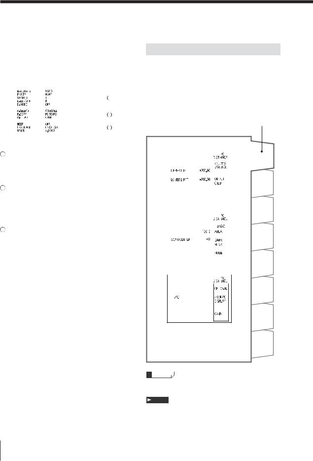
Outline of Measurement and Settings
The LT-9001 Series has a run mode that performs a measurement, and a program mode that sets the measurement conditions. Measuring various targets is possible by combining several measurement conditions.
Run mode screen |
Chapter |
|
Program mode screen |
||
DISTANCE (Displacement mode) |
2 |
|
<OUTPUT settings> |
||
Measurement screen |
OperationsBasic |
|
|
||
|
<BASIC settings> |
|
Light intensity screen |
|
|
|
<OPTIONAL settings> |
|
Pause screen |
|
|
|
<Environment settings> |
|
PROFILE (Profile mode) |
The run mode and the |
|
program mode are |
||
Measurement screen |
switched every time the |
|
[PROG/RUN] switch is |
||
|
||
|
pushed down. |
|
Light intensity screen |
|
|
Pause screen |
|
|
E LT-9001-IM |
2-3 |
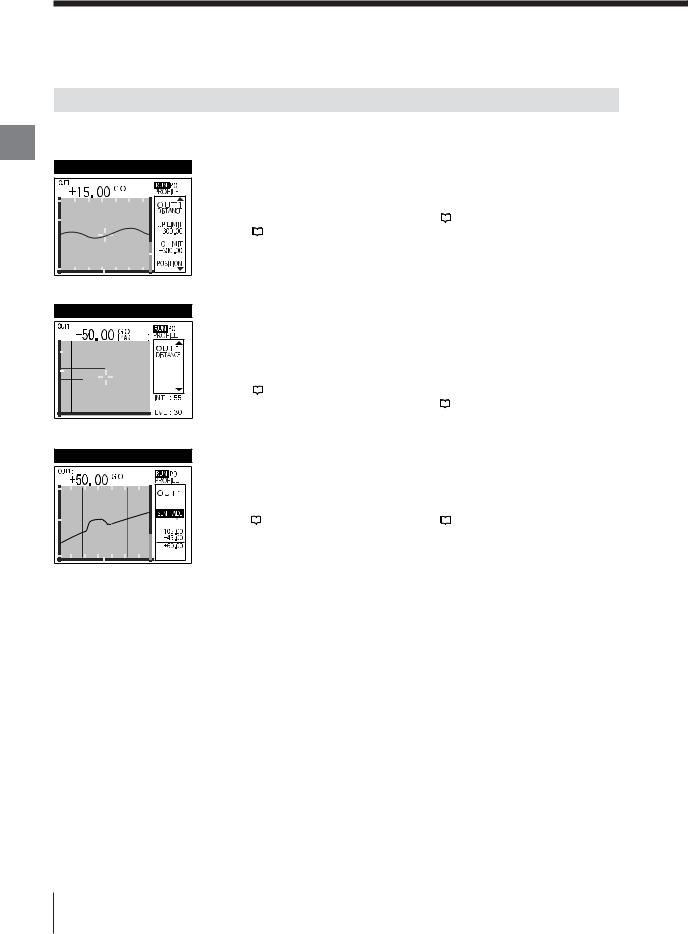
Outline of Measurement and Settings
Run Mode
The run mode displays the measurement screen, the light intensity screen, and the pause screen
Chapter
2 |
interchangeably. |
|
|
Operations Basic |
MEASUREMENT |
|
 The measured value and the graph can be displayed.
|
Displacement mode |
|
Profile mode |
|
|
|
|
Displays the temporal change of the |
Displays the profile of the target. |
||
measured value. |
|
Chapter 4 "Measurement Screen" |
|
|
|||
|
Chapter 3 "Measurement Screen" |
|
(page 4-5) |
|
|||
|
(page 3-5) |
|
|
|
|
|
|
INT (Light intensity)
 The measured value and the graph of the amount of light the measurement surface receives can be displayed.
|
Displacement mode |
|
Profile mode |
|
|
|
|
Displays up to four peaks of light intensity. |
Displays the distribution of light intensity |
||
Changes the light intensity level. |
in reference with the scanning width. |
||
|
Chapter 3 "Light Intensity Screen" |
Changes the light intensity level. |
|
|
|||
|
(page 3-7) |
|
Chapter 4 "Light Intensity Screen" |
|
|
||
|
|
|
(page 4-8) |
|
|
|
|
Pause |
 Performs correction or measurement while suspending the update of the displayed graph.
|
Displacement mode |
|
Profile mode |
|
|
|
|
|
|
|
|
|
Chapter 3 "Pause Screen" (page 3-9) |
|
Chapter 4 "Pause Screen" (page 4-10) |
|
|
||
|
|
|
|
2-4 |
E LT-9001-IM |
Program Mode
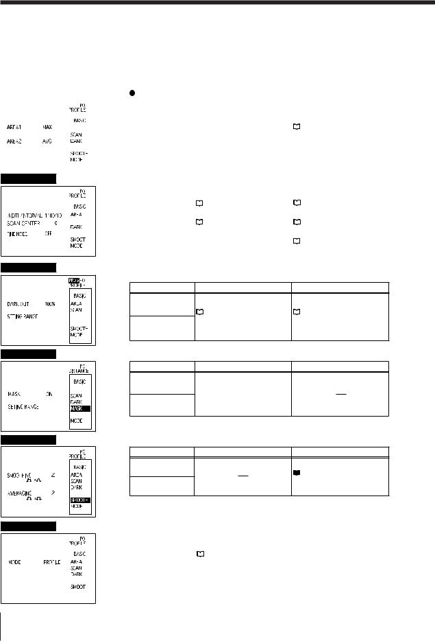
Four types of settings (OUTPUT settings, BASIC settings, OPTIONAL settings, and Environment settings) can be performed in the program mode according to the target to measure.
OUTPUT settings
Performs settings for OUT1 and OUT2 respectively.
LIMITS (Tolerance) |
|
|
Sets the upper and lower limits of the tolerance. |
|
|||||||||||
|
|
|
|
|
|
|
|
|
|
|
|
|
|
|
|
|
|
|
|
|
|
|
|
|
|
Setting item |
Displacement mode |
|
Profile mode |
||
|
|
|
|
|
|
|
|
|
|||||||
|
|
|
|
|
|
|
|
|
|
UPPER LIMIT |
|
|
Chapter 5 "OUT Settings" - "LIMITS" (page 5-7) |
||
|
|
|
|
|
|
|
|
|
|
|
|
||||
|
|
|
|
|
|
|
|
|
|
|
|||||
|
|
|
|
|
|
|
|
|
|
|
|
|
|||
|
|
|
|
|
|
|
|
|
|
LOWER LIMIT |
|
|
|
|
|
|
|
|
|
|
|
|
|
|
|
|
|
|
|
||
|
|
|
|
|
|
|
|
|
|
|
|
|
|||
|
|
|
|
|
|
|
|
|
|
|
|
|
|
|
|
|
|
|
|
|
|
|
|
|
|
|
|
|
|
|
|
|
|
|
|
|
|
|
|
|
|
|
|
|
|
|
|
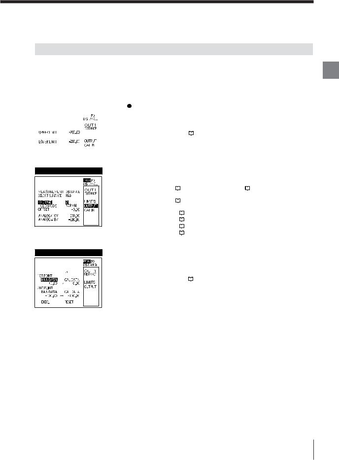
OUTPUT
CALIB (Calibration)
 Sets the measurement method and the processing of the measured data.
Setting item |
|
|
Displacement mode |
|
Profile mode |
|||
|
|
|
|
|
|
|
|
|
MEASURMENT |
|
Chapter 3 "OUT Settings" - |
|
Chapter 4 "OUT Settings" - |
||||
|
|
|||||||
|
"Measurement" (page 3-10) |
|
"Measurement" (page 4-12) |
|||||
|
|
|
||||||
SELECT SURFACE |
|
Chapter 3 "OUT Settings" - |
|
|
|
|
||
|
|
|
|
|
||||
|
"SELECT SURFACE" (page 3-12) |
|
|
|
|
|||
|
|
|
|
|
|
|||
AVERAGE |
|
|
Chapter 5 |
"OUT Settings" - "AVERAGE" (page 5-8) |
||||
|
|
|||||||
|
|
|
|
|
|
|
|
|
HOLD MODE |
|
|
Chapter 5 |
"OUT Settings" - "HOLD MODE" (page 5-9) |
||||
|
|
|||||||
|
|
|
|
|
|
|
|
|
OFFSET |
|
|
Chapter 5 |
"OUT Settings" - "OFFSET" (page 5-14) |
||||
|
|
|||||||
|
|
|
|
|
|
|
|
|
ANALOG output |
|
|
Chapter 5 |
"OUT Settings" - "ANALOG output" (page 5-15) |
||||
|
|
|||||||
|
|
|
|
|
|
|
|
|
 Calibrates the error caused by slant or refractive.
Setting item |
Displacement mode |
Profile mode |
|
|
|
|
|
|
|
|
|
Measured value |
|
|
|
and |
|
Chapter 5 "OUTPUT Settings" - "CALIB" (page 5-16) |
|
|
|||
calibrated value |
|
|
|
|
|
|
|
Chapter
2
Operations Basic
|
|
|
E LT-9001-IM |
2-5 |
|
Outline of Measurement and Settings
BASIC settings
Performs settings for the preprocessing common to both OUT1 and OUT2.
Chapter |
|
|
|
|
|
|
|
|
|
|
|
|
|
|
|
|
|
AREA |
|
|
|
|
|
|
|
|
Performs settings for the profile measurement method. |
||||||
2 |
|
|
|
|
|
|
|
|
|
|||||||
|
|
|
|
|
|
|
|
|
|
|
|
|
|
|
|
|
|
|
|
|
|
|
|
|
|
|
Setting item |
Displacement mode |
|
Profile mode |
|||
Basic |
|
|
|
|
|
|
|
|
|
|
AREA1 |
|
|
|
|
Chapter 4 "BASIC Settings" - |
Operations |
|
|
|
|
|
|
|
|
|
|
|
|
|
|
||
|
|
|
|
|
|
|
|
|
|
|
|
|
||||
|
|
|
|
|
|
|
|
|
|
|
|
|
|
|
||
|
|
|
|
|
|
|
|
|
|
AREA2 |
|
|
|
|
"AREA" (page 4-13) |
|
|
|
|
|
|
|
|
|
|
|
|
|
|
|
|
||
|
|
|
|
|
|
|
|
|
|
|
|
|
|
|
|
|
|
|
|
|
|
|
|
|
|
|
|
|
|
|
|
|
|
|
|
|
|
|
|
|
|
|
|
|
|
|
|
|
|
|
|
|
|
|
|
|
|
|
|
|
|
|
|
|
|
|
|
SCAN
 Performs settings for the swing width of a spot.
|
|
|
|
|
|
|
Setting item |
|
Displacement mode |
|
Profile mode |
||
|
|
|
|
|
|
|
|
|
|||||
|
|
|
|
|
|
|
SCAN WIDTH |
|
Chapter 3 "BASIC Settings" - |
|
Chapter 4 "BASIC Settings" - |
||
|
|
|
|
|
|
|
|
"Scan width/interval" (page 3-15) |
|
"Scan width/interval" (page 4-14) |
|||
|
|
|
|
|
|
|
|
|
|
||||
|
|
|
|
|
|
|
|
|
|
|
|
|
|
|
|
|
|
|
|
|
SCAN CENTER |
|
Chapter 3 "BASIC Settings" - |
|
Chapter 4 "BASIC Settings" - |
||
|
|
|
|
|
|
|
|
|
|||||
|
|
|
|
|
|
||||||||
|
|
|
|
|
|
|
(LT-9010 only) |
|
"Scan center" (page 3-16) |
|
"Scan center" (page 4-15) |
||
|
|
|
|
|
|
|
FINE MODE |
|
|
|
|
|
Chapter 4 "BASIC Settings" - |
|
|
|
|
|
|
|
|
|
|
|
|
||
|
|
|
|
|
|
|
|
|
|
|
|
"FINE mode" (page 4-15) |
|
|
|
|
|
|
|
|
|
|
|
|
|
|
|
|
|
|
|
|
|
|
|
|
|
|
|
|
|
DARK
MASK
 Performs settings for the processing for the case that the light intensity is lower than the setting range.
Setting item |
Displacement mode |
Profile mode |
DARKOUT
|
|
Chapter 3 "BASIC Settings" - |
Chapter 4 "BASIC Settings" - |
|
|
"DARK ALARM" (page 3-17) |
"DARK ALARM" (page 4-16) |
|
SETTING RANGE
 Performs settings for the range to be excluded from the measurement.
|
Setting item |
Displacement mode |
Profile mode |
|
MASK
 Chapter 3 "BASIC Settings" -
"MASK" (page 3-18)
SETTING RANGE
SMOOTH
 Performs settings for the functions that stabilize the profile waveform.
|
Setting item |
Displacement mode |
Profile mode |
|
SMOOTHING
 Chapter 4 "BASIC Settings" -
"SMOOTH" (page 4-17)
AVERAGING
MODE
 Toggles between the displacement mode and the profile mode.
|
|
|
|
|
|
Setting item |
|
Displacement mode |
Profile mode |
|
|||||||||
|
|
|
|
|
|
MODE |
|
Chapter 2 "Selection Method of the Run Mode" (page 2-12) |
|
|
|
|
|
|
|
|
|||
|
|
|
|
|
|
|
|
|
|
|
|
|
|
|
|
|
|
|
|
|
|
|
|
|
|
|
|
|
|
|
|
|
|
|
|
|
|
|
|
2-6 |
E LT-9001-IM |
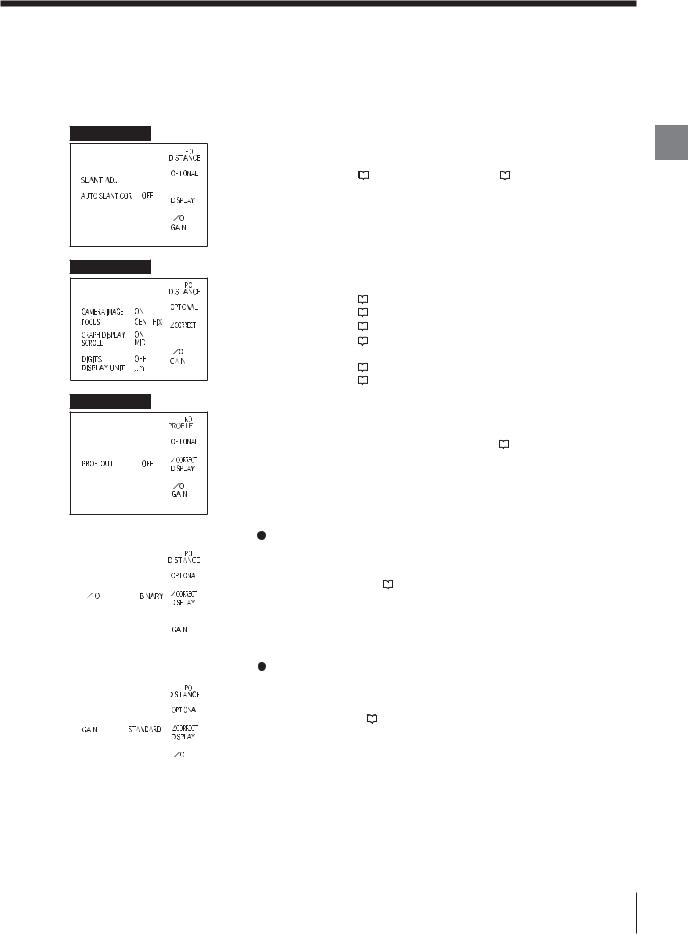
OPTIONAL settings
Perform settings for the additional functions common to both OUT1 and OUT2.
SLANT
DISPLAY
PROF OUT
 Performs settings for the automatic slant correction on the target. (LT-9010 only)
|
|
|
|
|
Setting item |
|
|
Displacement mode |
|
|
Profile mode |
|
|
||||||||||
|
|
|
|
|
|
|
|
|
|
|
|
|
|
|
|
|
|
|
|
|
|
|
|
|
|
|
|
|
SLANT ADJ |
|
|
Chapter 3 "OPTIONAL Settings" |
|
|
Chapter 4 "OPTIONAL Settings" |
|
|
|
|
|
|
|
|
|
|||
|
|
|
|
|
|
|
- "SLANT" (page 3-19) |
|
|
- "SLANT" (page 4-18) |
|
|
|
|
|
|
AUTO SLANT COR |
|
|
|
|
||
|
|
|
|
||||||||
|
|
|
|
|
|
|
|
|
|
|
|
|
|
|
|
|
|
|
|
|
|
|
|
|
|
|
|
|
|
|
|
|
|
|
|
|
|
|
|
|
|
|
|
|
|
|
|
|
|
|
|
|
|
|
|
|
|
|
|
|
|
|
|
|
|
|
|
|
|
|
|
|
|
|
|
|
|
|
|
|
|
|
|
|
|
|
|
|
|
|
|
|
|
|
|
 Performs settings for the measured value display.
|
|
|
|
|
|
|
|
Setting item |
|
Displacement mode |
Profile mode |
|||
|
|
|
|
|
||||||||||
|
|
|
|
|
|
|
|
|
|
|
|
|
|
|
|
|
|
|
|
|
|
|
CAMERA IMAGE |
|
Chapter 5 |
"OPTIONAL Settings" - "CAMERA IMAGE" (page 5-18) |
|||
|
|
|
|
|
|
|
|
|
||||||
|
|
|
|
|
|
|
|
FOCUS |
|
Chapter 5 |
"OPTIONAL Settings" - "FOCUS" (page 5-18) |
|||
|
|
|
|
|
|
|
|
|
|
|
|
|
|
|
|
|
|
|
|
|
|
|
GRAPH DISPLAY |
|
Chapter 5 |
"OPTIONAL Settings" - "GRAPH DISPLAY" (page 5-18) |
|||
|
|
|
|
|
|
|
|
|
||||||
|
|
|
|
|
|
|
|
SCROLL |
|
Chapter 5 "OPTIONAL Settings" |
|
|
|
|
|
|
|
|
|
|
|
|
|
- "SCROLL" (page 5-18) |
|
|
|
||
|
|
|
|
|
|
|
|
|
|
|
||||
|
|
|
|
|
|
|
|
|
|
|
|
|
||
|
|
|
|
|
|
|
|
DIGITS |
|
Chapter 5 "OPTIONAL Settings" - "DIGITS" (page 5-18) |
||||
|
|
|
|
|
|
|
|
|
||||||
|
|
|
|
|
|
|
|
|
|
|
|
|
|
|
|
|
|
|
|
|
|
|
DISPLAY UNIT |
|
Chapter 5 "OPTIONAL Settings" - "DISPLAY UNIT" (page 5-19) |
||||
|
|
|
|
|
|
|
|
|
||||||
|
|
|
|
|
|
|
|
|
|
|
|
|
|
|
 Performs settings to output the waveform data of the target shape.
|
|
|
|
|
|
|
Setting item |
Displacement mode |
|
|
Profile mode |
||
|
|
|
|||||||||||
|
|
|
|
|
|
|
PROF OUT |
|
|
|
|
|
Chapter 4 "OPTIONAL Settings" |
|
|
|
|
|
|
|
|
|
|
|
|
- "PROFILE" (page 4-19) |
|
|
|
|
|
|
|
|
|
|
|
|
|||
|
|
|
|
|
|
|
|
|
|
|
|
|
|
|
|
|
|
|
|
|
|
|
|
|
|
|
|
|
|
|
|
|
|
|
|
|
|
|
|
|
|
|
|
|
|
|
|
|
|
|
|
|
|
|
|
|
|
|
|
|
|
|
|
|
|
|
|
|
|
|
|
|
|
|
|
|
|
|
|
|
|
|
|
|
|
|
|
|
|
|
|
|
|
|
|
|
|
|
|
|
|
|
|
|
|
|
|
|
|
|
|
|
|
|
|
|
|
|
|
|
|
|
|
|
|
|
I/O |
|
|
|
|
|
|
Performs settings for the control I/O. |
|
|||
|
|
|
|
|
|
|
|
|
|
|
|
|
|
|
|
|
|
|
|
|
|
Setting item |
Displacement mode |
Profile mode |
|
|
|
|
|
|
|
|
|
|
|
|
|
|
|
|
|
|
|
|
|
|
|
I/O |
|
Chapter 5 "OPTIONAL Settings" - "I/O" (page 5-20) |
|
|
|
|
|
|
|
|
|
|
|
|||
|
|
|
|
|
|
|
|
|
|
|||
|
|
|
|
|
|
|
|
|
||||
|
|
|
|
|
|
|
|
|
|
|||
|
|
|
|
|
|
|
|
|
|
|
|
|
|
|
|
|
|
|
|
|
|
|
|
|
|
|
|
|
|
|
|
|
|
|
|
|
|
|
|
|
|
|
|
|
|
|
|
|
|
|
|
|
|
|
|
|
|
|
|
|
|
|
|
|
|
|
|
|
|
|
|
|
|
|
|
|
|
|
|
|
|
|
|
|
|
|
|
|
|
|
|
|
|
|
|
|
|
|
|
|
|
|
|
|
|
|
|
|
|
|
|
|
|
|
|
|
|
|
|
|
|
|
|
|
|
|
|
|
|
|
GAIN |
|
|
|
|
|
|
Performs settings for the sensitivity toward light intensity to be received. |
|||
|
|
|
|
|
|
|
|
|
|
|
|
|
|
|
|
|
|
|
|
Setting item |
|
Displacement mode |
Profile mode |
|
|
|
|
|
|
|
|
|
|
|
|
|
|
|
|
|
|
|
|
GAIN |
|
Chapter 5 "OPTIONAL Settings" - "GAIN" (page 5-20) |
|
|
|
|
|
|
|
|
|
|
|||
|
|
|
|
|
|
|
|
||||
|
|
|
|
|
|
|
|
|
|||
|
|
|
|
|
|
|
|
|
|
|
|
|
|
|
|
|
|
|
|
|
|
|
|
|
|
|
|
|
|
|
|
|
|
|
|
|
|
|
|
|
|
|
|
|
|
|
|
|
|
|
|
|
|
|
|
|
|
|
|
|
|
|
|
|
|
|
|
|
|
|
|
|
|
|
|
|
|
|
|
|
|
|
|
|
|
|
|
|
|
|
|
|
|
|
|
|
|
|
|
|
|
|
|
|
|
|
|
|
|
|
|
|
|
|
|
|
|
|
|
|
|
|
|
|
|
|
|
|
|
|
|
Chapter
2
Operations Basic
E LT-9001-IM |
2-7 |
Outline of Measurement and Settings
|
Environment settings |
||||||||||||
|
Performs basic settings that are necessary in |
||||||||||||
|
operating the LT-9001 Series. |
||||||||||||
Chapter |
|||||||||||||
|
|
|
|
|
|
|
|
|
|
|
|
||
2 |
|
|
|
|
|
|
|
|
|
|
|
|
|
|
|
|
|
|
|
|
|
|
|
|
|
||
Basic |
|
|
|
|
|
|
|
|
|
|
|
|
|
Operations |
|
|
|
|
|
|
|
|
|
|
1 |
||
|
|
|
|
|
|
|
|
|
|
||||
|
|
|
|
|
|
|
|
|
|
|
|||
|
|
|
|
|
|
|
|
|
|
|
|
2 |
|
|
|
|
|
|
|
|
|
|
|
|
|
||
|
|
|
|
|
|
|
|
|
|
|
|||
|
|
|
|
|
|
|
|
|
|
|
|||
|
|
|
|
|
|
|
|
|
|
|
|
3 |
|
|
|
|
|
|
|
|
|
|
|
|
|
|
|
Program Function
Eight programs can be toggled among program numbers 0 to 7 in the LT-9001 Series.
You can register a set of parameters as a program according to the run mode or the measurement target.
The set parameters can easily be changed if calling up the desired program as needed.
Program No.
<OUT settings> |
|
||||||||||||||
1 RS-232C |
|
|
|
|
|
|
|
|
|
|
|
|
|
P0 |
|
Performs settings for the communication |
|
|
|
|
|
|
|
|
|
|
|
|
|
||
|
|
|
|
|
|
|
|
|
|
|
|
|
|
||
|
|
|
|
|
|
|
|
|
|
|
|
|
|
||
specifications of the RS-232C interface. |
|
|
|
|
|
|
|
|
|
|
|
|
|
P1 |
|
|
|
|
|
|
|
|
|
|
|
|
|
|
|||
|
|
|
|
|
|
|
|
|
|
|
|
|
|||
|
|
|
|
|
|
|
|
|
|
|
|
|
|||
2 Program operations |
|
|
|
|
|
|
|
|
|
|
|
|
|
||
|
|
|
|
|
|
|
|
|
|
|
|
|
|||
|
|
|
|
|
|
|
|
|
|
|
|
|
|||
|
|
|
|
|
|
|
|
|
|
|
|
|
|||
|
|
|
|
|
|
|
|
|
|
|
|
|
|||
|
|
|
|
|
|
|
|
|
|
|
|
|
|||
|
|
|
|
|
|
|
|
|
|
|
|
|
|
||
Performs settings for the program number switching |
|
|
|
|
|
|
|
|
|
|
|
|
|
|
|
|
|
|
|
|
|
|
|
|
|
|
|
|
|
||
method, copying program settings, and resetting the |
P2 |
||||||||||||||
<BASIC settings> |
|||||||||||||||
program to default. |
|
|
|
|
|
|
|
|
|
|
|
|
|||
|
|
|
|
|
|
|
|
|
|
|
|
|
|
||
3 Others |
|
|
|
|
|
|
|
|
|
|
|
|
|
P3 |
|
|
|
|
|
|
|
|
|
|
|
|
|
|
|||
|
|
|
|
|
|
|
|
|
|
|
|
|
|||
|
|
|
|
|
|
|
|
|
|
|
|
|
|||
|
|
|
|
|
|
|
|
|
|
|
|
|
|||
Performs settings for the beep sound, user interface |
|
|
|
|
|
|
|
|
|
|
|
|
|
||
|
|
|
|
|
|
|
|
|
|
|
|
|
|||
language, and span of the measuring unit. |
|
|
|
|
|
|
|
|
|
|
|
|
|||
|
|
|
|
|
|
|
|
|
|
|
|
|
|
P4 |
|
|
|
|
|
|
|
|
|
|
|
|
|
|
|
||
<OPTIONAL settings> |
|||||||||||||||
|
|||||||||||||||
|
|
|
|
|
|
|
|
|
|
|
|
|
|
P5 |
|
|
|
|
|
|
|
|
|
|
|
|
|
|
|
||
|
|
|
|
|
|
|
|
|
|
|
|
|
|
||
|
|
|
|
|
|
|
|
|
|
|
|
|
|
||
|
|
|
|
|
|
|
|
|
|
|
|
|
|
||
|
|
|
|
|
|
|
|
|
|
|
|
|
|
||
|
|
|
|
|
|
|
|
|
|
|
|
|
|
||
|
|
|
|
|
|
|
|
|
|
|
|
|
|
||
|
|
|
|
|
|
|
|
|
|
|
|
|
|
|
|
|
|
|
|
|
|
|
|
|
|
|
|
|
|
|
|
|
|
|
|
|
|
|
|
|
|
|
|
|
|
|
|
|
|
|
|
|
|
|
|
|
|
|
|
|
|
|
|
|
|
|
|
|
|
|
|
|
|
|
|
|
|
|
|
|
|
|
|
|
|
|
|
|
|
|
|
|
|
|
|
P6
<AUTO-ZERO parameter>
P7
 Refer to "Program Change" (page 5-6) for a program switching method.
Note
Environment settings are not saved.
2-8 |
E LT-9001-IM |
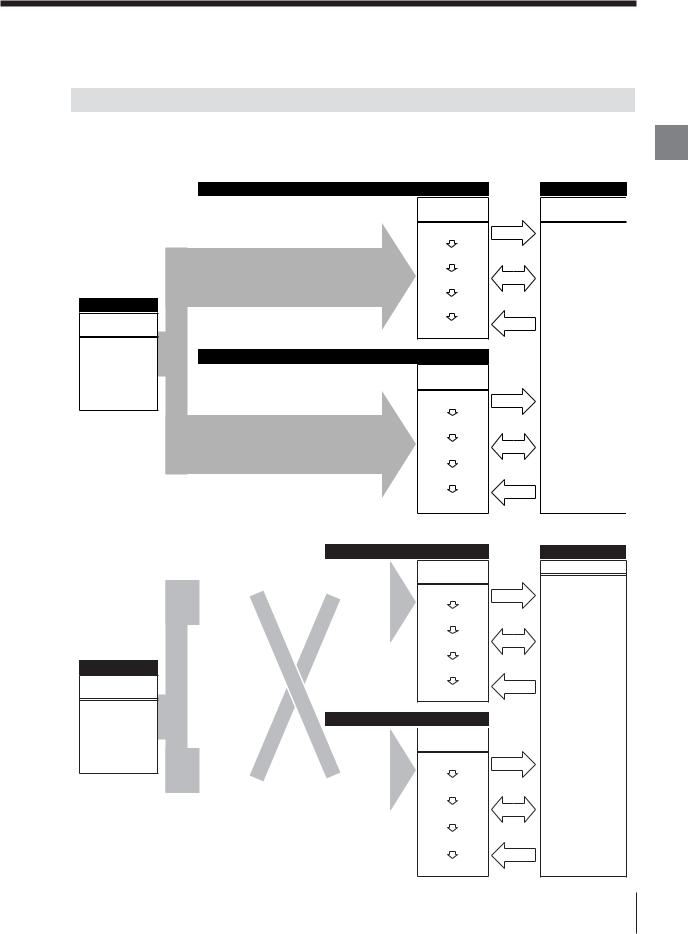
Flow of Measurement
The LT-9001 Series can display and output the measured value of OUT1 and OUT2.
Displacement mode
Basic/Optional
Measurement condition
•INT parameter
•SCAN
•DARK
•SMOOTH
• CORRECT
Profile mode
Basic/Optional
Measurement condition
•INT parameter
•SCAN
•DARK
•SMOOTH
• CORRECT
|
|
OUT1 |
Measurement |
|
Select Surface |
|
|
|
|
|
|
• DISTANCE |
|
• MAX |
• SLANT |
|
• M1 |
• SLANT |
|
• M2 |
• THICKNESS |
|
• +4P to +1P |
|
|
• –1P to –4P |
|
|
|
|
|
|
|
|
OUT2 |
Measurement |
|
Select Surface |
|
|
|
• DISTANCE |
|
• MAX |
• SLANT |
|
• M1 |
• THICKNESS |
|
• M2 |
|
|
• +4P to +1P |
|
|
• –1P to –4P |
|
||
|
|
|
AREA1 (A1) |
|
OUT1 |
||
|
|
|
|
|
AREA |
|
Select |
|
|
condition |
|
measurement |
|
|
|
||||
• AREA range |
|
• A1 |
|
|
• AVG |
|
• A2 |
|
|
• MAX |
|
• A1–A2 |
|
|
• MIN |
|
• A1+A2 |
|
|
• DIFF |
|
|
|
|
|
|
|
|
|
|
|
|
|
|
AREA2 (A2) |
|
OUT2 |
||
|
|
|
|
|
AREA |
|
Select |
|
|
condition |
|
measurement |
|
|
• AREA range |
|
• A1 |
|
|
• AVG |
|
• A2 |
|
|
• MAX |
|
• A1–A2 |
|
|
|
||||
• MIN |
|
• A1+A2 |
|
|
|
||||
• DIFF |
|
|
|
|
|
|
|
|
|
• AREA |
|
|
|
|
|
|
|
|
|
Measured value processing
CALIB
AVERAGE
HOLD MODE
AUTO-ZERO
OFFSET
Measured value processing
CALIB
AVERAGE
HOLD MODE
AUTO-ZERO
OFFSET
Measured value processing
CALIB
AVERAGE
HOLD MODE
AUTO-ZERO
OFFSET
Measured value processing
CALIB
AVERAGE
HOLD MODE
AUTO-ZERO
Output
I/O
Input
Output
I/O
Input
Output
I/O
Input
Output
I/O
Input
OFFSET
I/O
Measured value
Judgment output (LIMITS)
Analog output
Binary output
RS-232C
TIMING
RESET
ZERO
I/O
Measured value
Judgment output (LIMITS)
Analog output
Binary output
RS-232C
TIMING
RESET
ZERO
Chapter
2
Operations Basic
E LT-9001-IM |
2-9 |
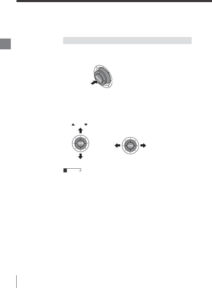
Operations
Chapter
2
Operations Basic
The LT-9001 Series is operated using the remote control console.
How to Use the [ENTER] Button
Pressing the button straight down
•For selecting a menu item
•For fixing a setting
Press
Tilting the button up, down, left or right
The button moves up, down, left and right. This is used to perform the following operations.
•Moving to another item
•Entering a value such as a tolerance
[ ] and [ ] buttons |
[t] and [s] buttons |
|
Moves upward |
|
|
|
Moves to |
Moves to |
|
the left |
the right |
Moves downward
The operation to tilt the [ENTER] button up or down is described as [▲] or [▼] button in this manual.
The operation to tilt the [ENTER] button left or right is described as [t] or [s] button.
2-10 |
E LT-9001-IM |
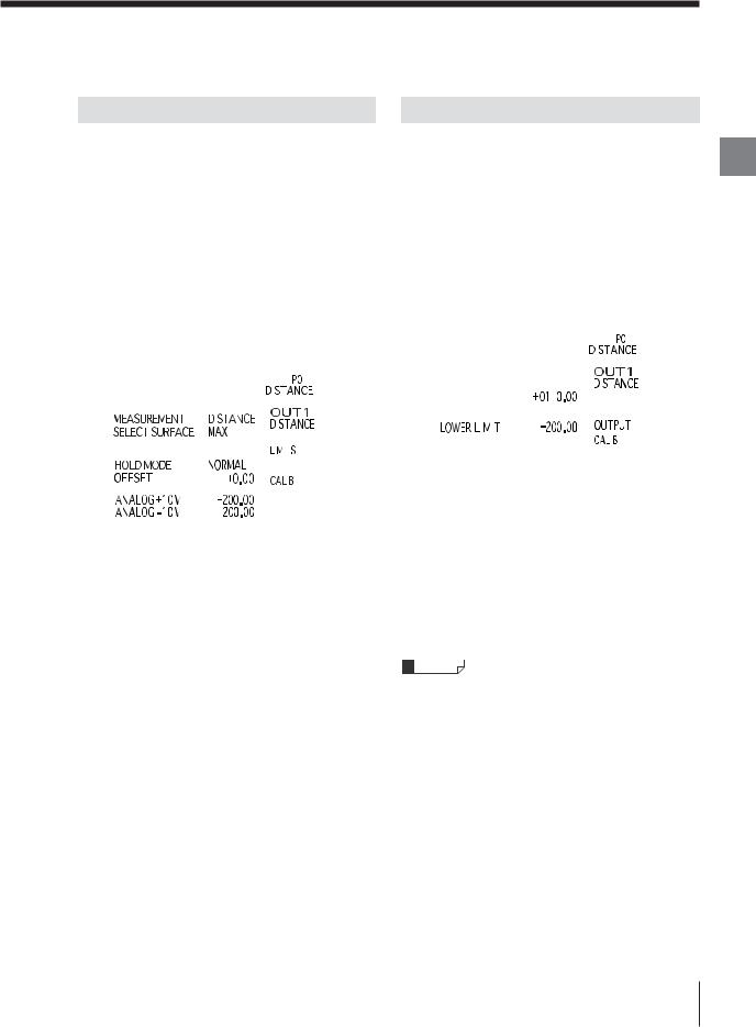
Selecting an Item
The procedure used to select or to enter items/values
such as parameters is explained as follows.
1 |
Place the cursor on the item you want to set |
|||||||||||
|
by using the [▲], [▼], [t] and [s] buttons. |
|||||||||||
2 |
Press the [ENTER] button. |
|||||||||||
|
The item on which the cursor was placed at step |
|||||||||||
|
1 is selected. |
|||||||||||
3 |
Repeat step 1 and 2 to change the selected |
|||||||||||
|
item or the parameter. |
|||||||||||
|
|
|
|
|
|
|
|
|
|
|
|
|
|
|
|
|
|
|
|
|
|
|
|
|
|
|
|
|
|
|
|
|
|
|
|
|
|
|
|
|
|
|
|
|
|
|
|
|
|
|
|
|
|
|
|
|
|
|
|
|
|
|
|
|
|
|
|
|
|
|
|
|
|
|
|
|
|
|
|
|
|
|
|
|
|
|
|
|
|
|
|
|
|
|
|
|
|
|
|
|
|
|
|
|
|
|
|
|
|
|
|
|
|
|
|
|
|
|
|
|
|
|
|
|
|
|
|
|
|
|
|
|
|
|
|
|
|
|
|
|
|
|
|
|
|
|
|
|
|
|
|
|
|
|
|
|
|
|
|
|
|
|
|
|
|
|
|
|
|
|
|
|
|
|
|
|
|
|
|
|
|
|
|
|
|
|
|
|
|
|
|
|
|
|
|
|
|
|
|
|
|
|
|
|
|
|
|
|
|
|
|
|
|
|
|
|
|
|
|
|
|
|
|
|
|
|
|
|
|
|
|
|
|
When you want to cancel the operation
If you press the [ESCAPE] button on the remote
control console, the cursor moves to the item
selected immediately before.
Entering a Value
The procedure used to enter a value such as the
tolerance is explained as follows.
1 |
Select the item whose value is to be entered. |
|||||||||||
2 |
Specify the digit of the entering value with the |
|||||||||||
|
[t] and [s] buttons. |
|||||||||||
3 |
Specify the value that you want to enter with |
|||||||||||
|
the [▲] and [▼] buttons. |
|||||||||||
|
|
|
|
|
|
|
|
|
|
|
|
|
|
|
|
|
|
|
|
|
|
|
|
|
|
|
|
|
|
|
|
|
|
|
|
|
|
|
|
|
|
|
|
|
|
|
|
|
|
|
|
|
|
|
|
|
|
|
|
|
|
|
|
|
|
|
|
|
|
|
|
|
|
|
|
|
|
|
|
|
|
|
|
|
|
|
|
|
|
|
|
|
|
|
|
|
|
|
|
|
|
|
|
|
|
|
|
|
|
|
|
|
|
|
|
|
|
|
|
|
|
|
|
|
|
|
|
|
|
|
|
|
|
|
|
|
|
|
|
|
|
|
|
|
|
|
|
|
|
|
|
|
|
|
|
|
|
|
|
|
|
|
|
|
|
|
|
|
|
|
|
|
|
|
|
|
|
|
|
|
|
|
|
|
|
|
|
|
|
|
|
|
|
|
|
|
|
|
|
|
|
|
|
|
|
|
|
4 Press the [ENTER] button after changing the value.
The specified value is fixed.
When you want to cancel the changed value
Press the [ESCAPE] button before pressing the [ENTER] button in step 3 above.
If the [ZERO] button is pressed while changing the value, the value can be set to zero.
Chapter
2
Operations Basic
E LT-9001-IM |
2-11 |
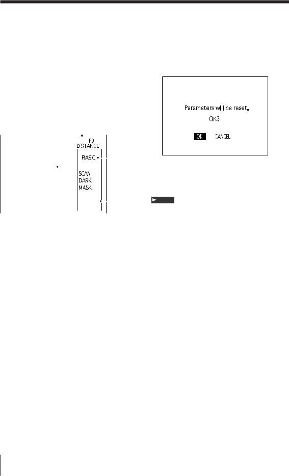
Selection Method of the Run Mode
|
Select either the displacement mode or the profile |
||||||||||||||||||
|
mode according to the measurement required. |
||||||||||||||||||
|
(Only displacement mode is available in the LT- |
||||||||||||||||||
Chapter |
|||||||||||||||||||
|
|
|
|
|
|
|
|
|
|
|
|
|
|
|
|
|
|
||
2 |
9030 (M). |
|
|
|
|
|
|
|
|
|
|
|
|||||||
|
|
|
|
|
|
|
|
|
|
|
|
|
|
|
|
|
|
||
Basic |
|
|
|
|
|
|
|
|
|
|
|
|
|
|
|
|
|
|
|
|
Operational Flow |
|
|
|
|
|
|
|
|
|
|
|
|||||||
Operations |
|
|
|
|
|
|
|
|
|
|
|
|
|
|
|
|
|
|
|
The operational flow in selecting the displacement |
|||||||||||||||||||
|
|||||||||||||||||||
|
mode or the profile mode is as follows. |
||||||||||||||||||
|
5, 6 |
|
2 |
|
|
|
|
|
|
|
|
||||||||
|
|
|
|
|
|
|
|
|
|
|
|
|
|
|
|
|
3 |
|
|
|
|
|
|
|
|
|
|
|
|
|
|
|
|
|
|
|
|
||
|
|
|
|
|
|
|
|
|
|
|
|
|
|
|
|
|
|
||
|
|
|
|
|
|
|
|
|
|
|
|
|
|
|
|
|
|
||
|
|
|
|
|
|
|
|
|
|
|
|
|
|
|
|
|
|
||
|
|
|
|
|
|
|
|
|
|
|
|
|
|
|
|
|
|
||
|
|
|
|
|
|
|
|
|
|
|
|
|
|
|
|
||||
|
|
|
|
|
|
|
|
|
|
|
|
|
|
|
|||||
|
|
|
|
|
|
|
|
|
|
|
|
|
|
|
|
|
|
|
|
|
|
|
|
|
|
|
|
|
|
|
|
|
|
|
|
|
|
|
|
|
|
|
|
|
|
|
|
|
|
|
|
|
|
|
|
|
|
|
|
|
|
|
|
|
4 |
|||
|
|
|
|
|
||||
|
|
|
|
|
|
|
|
|
|
|
|
|
|
||||
1 |
Turn on the power of the controller. |
|||||||
2 |
Slide the [PROG/RUN] switch downward on |
|||||||
|
the remote control console to display the |
|||||||
|
program mode screen. |
|||||||
3 |
Select [BASIC] with the [▲] and [▼] buttons |
|||||||
|
and press the [ENTER] button. |
|||||||
|
The basic setting screen is displayed. |
|||||||
4 |
Place the cursor on [MODE] with the [▲] and |
|||||||
|
[▼] buttons and press the [ENTER] button. |
|||||||
|
The cursor moves to [MODE] on the mode |
|||||||
|
setting screen. |
|||||||
5 |
Press the [ENTER] button and move the |
|||||||
|
cursor to the mode currently selected. |
|||||||
|
When the setting is performed for the first time, |
|||||||
|
[DISTANCE] is displayed. |
|||||||
6 |
Select [PROFILE] or [DISTANCE] with the [▲] |
|||||||
|
and [▼ ] buttons and press the [ENTER] |
|||||||
button.
The confirmation screen is displayed.
7 Select [OK] with the [▲] and [▼] buttons and press the [ENTER] button.
The mode is switched to the selected run mode.
8 Slide down the [PROG/RUN] switch on the remote control console to display the run
mode screen.
Note
All parameters are reset to the default value if
displacement mode/profile mode is changed.
2-12 |
E LT-9001-IM |
Loading...