


96M1382
RGB Digital Fiberoptic Sensor
CZ-V21A(P)/V22A(P)
Instruction Manual
BE SURE TO READ THESE MESSAGES CAREFULLY
• The CZ-V21(P)/V22(P) is just intended for the detection of target Warning objects. Do not use the CZ-V21(P)/V22(P) in a safety circuit to pro-
tect the human body.
•The CZ-V21(P)/V22(P) does not have an explosion-proof structure. Do not use it in a location where any flammable gases, liquid or powder exist.
•The CZ-V21(P)/22(P) is a direct current type sensor. Application of the AC power may lead to burst or fire.
•Do not directly look at the emitted LED beam.
•The CZ-H32/H35S/H37S/H72 are the Class 1 LED product in which the light source LED is located in the amplifier unit.
•The CZ-H52 is the Class 1M LED product.
*When using the CZ-H52, be sure to read Precaution on Using CZH52 on page 8.
ACCESSORIES
■ Amplifier unit
• Mounting bracket: 1 |
• End unit: 2 |
• Instruction manual: 1 |
Supplied with the CZ-V21A(P) |
Supplied with the CZ-V22A(P) |
|
■ Sensor head
Common: |
• Mounting bracket: 1 (two types, one of each for the CZ-H72) |
CZ-H32/H35S/H37 only : |
• Board nut: 1 |
• M3 x 20 screw: 2 |
|
CZ-H52 only : |
• M3 x 22 screw: 2 |
•Fiber insertion port cover seal: 1
•Ultraviolet ray spot check sheet : 1
CZ-H72 only : |
• M3 x 30 screw: 2 |
|
• M3 x 6 screw: 2 |
PART NAMES |
|
|
|
|
|
|
|
|
|
■ Amplifier unit |
|
|
|
|
|
|
|
|
|
|
|
|
|
|
|
C |
|
MODE |
SET |
|
|
|
|
|
|
|
|
|
|
CZ-V22A(P) |
1 |
2 |
3 |
4 |
BANK |
|
|
||
A |
|
B |
|
|
|||||
|
|
|
|
|
1 |
2 |
3 |
4 |
|
|
|
OUT |
|
|
|
|
|
|
|
|
|
|
|
|
|
|
|
|
|
|
|
Fixing lever |
Output indicator |
Receiver connector port |
Display |
Manual adjustment button |
MODE button |
Connection protection cover Connection connector |
SET button |
Dust cover |
|||
CZ-V21A(P) |
|
|
|
|
C |
|
MODE |
SET |
1 |
2 |
3 |
4 |
BANK |
|
|
||
A |
|
B |
|
|
||||
|
|
|
|
|
|
|
||
|
|
|
|
1 |
2 |
3 |
4 |
|
|
OUT |
|
|
|
|
|
|
|
Display
Color indicator* |
|
C |
|
|
Current value monitor (red) |
(Lights at C/C+I mode) |
|
|
|
||
|
|
|
|
|
|
Bank indicator |
BANK |
|
|
||
(At C/C+I mode) |
A |
|
B |
|
Setting value monitor (green) |
Channel indicator |
1 |
2 |
3 |
4 |
|
|
|
|
|
|
|
* Film calibration indicator when using the CZ-H72
■ Sensor head
CZ-H32 |
|
CZ-H35S/H37S |
|
Spot selection switch |
|
|
Light emission fiber |
|
|
cable |
Detection |
Detection |
|
|
23H |
indicator |
|
indicator |
-Z |
|
C |
|
|
|
Emitter |
|
|
Light reception |
|
Emitter |
cable |
|
Receiver |
|
Receiver |
|
|
Light emission fiber cable
H35S |
|
- |
|
|
CZ |
Light reception cable
CZ-H52
Receiver |
|
|
UV irradiation indicator |
|
|
|
(green) |
|
UV |
ON |
|
|
|
|
|
|
|
TE |
CT |
|
DE |
|
|
|
|
-H |
52 |
|
CZ |
|
|
|
|
|
|
Detection indicator
(red)
Emitter
CZ-H72
Detection indicator |
Light emission fiber cable |
|
|
Spot selection switch |
|
Emitter |
|
|
Light reception cable |
Receiver
■ Installing the supplied brackets on the CZ-H72
Install the two supplied brackets by combining them as shown below.
The sensor angle can be adjusted within 90° (± 45°). (Refer to the lower right of page 9.)
E CZ-V21A(P)/V22A(P)-IM |
1 |
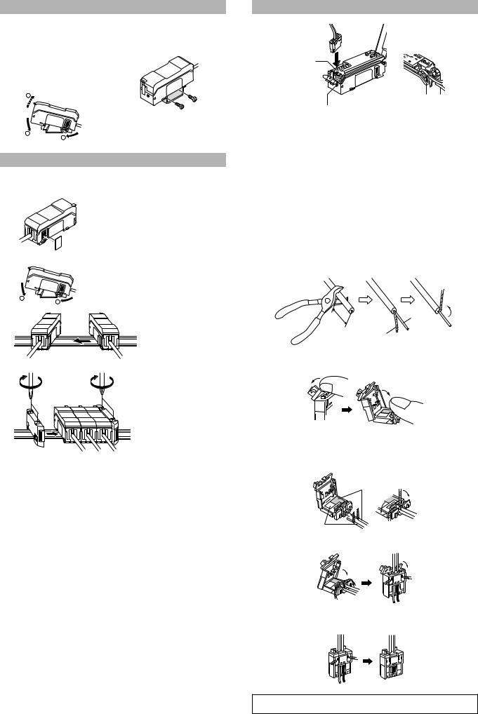
MOUNTING THE AMPLIFIER UNIT
■ Mounting on a DIN rail |
■ Mounting on a bracket |
Hook the claw located on the bottom of the amplifier unit to the DIN rail. While pushing the amplifier unit in the direction of the arrow 1, push it down in the direction of the arrow 2. To dismount the amplifier unit, while pushing the main body in the direction of the arrow 1, raise the body in the direction of the arrow 3.
3
2
1
Mount the amplifier unit using the supplied mounting bracket as shown in the figure.
CONNECTING SEVERAL AMPLIFIER UNITS
Up to three sub-units CZ-V22A(P) can be mounted adjacent to the main unit CZV21A(P). By connecting several units, the number of power cables can be reduced.
1Remove the protection cover on the side of the amplifier.
2Mount the sub-unit on the DIN rail.
2
1
3Connect the sub unit to the connector on the main unit by sliding the sub unit toward the main unit until a clicking sound is heard.
4Mount the end units on both sides.
Fasten the screws on the top of the end units (at two positions on both end units) with the Philips screwdriver.
MOUNTING THE SENSOR HEAD
|
4 |
3 |
|
|
|
|
Connector |
B |
2 |
1 |
|
|
|
C |
|
4 |
3 |
|
UO |
|
|
KN |
AB |
A |
|
T |
|
port |
|
|
|
|
2 |
|
|
|
|
|
1 |
|
Fiber cable port
1 Open the dust cover.
2 Tilt the fixing levers.
3 Insert the fiber cable and the connector of the sensor head into the corresponding ports.
Be sure to insert the fiber cable until it reaches the deepest end (the inserted length: about 20 mm).
*The CZ-H52 is not supplied with the fiber cable.
Attach the supplied cover seal on the fiber cable insertion slot when using the CZ-H52.
4 Lock them with the fixing levers.
5
■
1
90°
Core
Shielded wire
2 Tilt the lid of the connector in the direction of the arrow indicated on its left-hand side, and open the connector.
3 Insert the wires to the deepest end with the shielded wires bent upward. Bend the shielded wires along the grooves in the direction of the arrows. Be sure to match the colors of the sticker on the connector with those of the shielded wires.
Red
White
4 Close the connector to crimp down the wires, and tilt the top to lock.
5 Trim off the wires sticking out of the connector by using a nipper or the like.
Note Limit the reconnection to two times.
2 |
E CZ-V21A(P)/V22A(P)-IM |
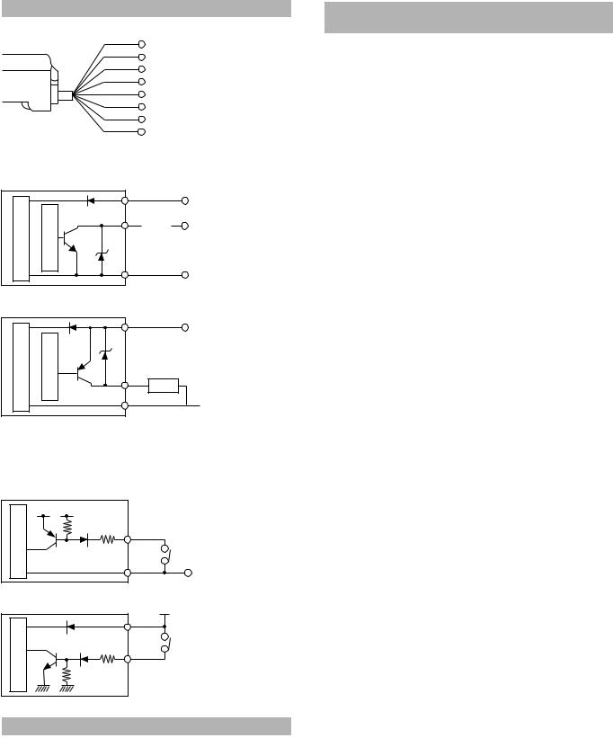
INPUT/OUTPUT CIRCUIT SCHIMATIC
■ Connection diagram
|
Brown* |
24 VDC |
|
|
Black |
||
|
Output 1 |
||
|
White |
||
|
Output 2 |
||
|
Gray |
||
|
Output 3 |
||
|
Orange |
||
|
Output 4 |
||
|
Pink* |
||
|
External calibration |
||
|
Purple |
||
|
External bank selection/external shift |
||
* |
Blue* |
||
0 V |
|||
CZ-V21A and V21AP only |
|
■ Output circuit |
|
|
|
||
CZ-V21A • V22A |
*CZ-V21A only |
|
|||
|
|
Brown* |
24 VDC |
||
circuitmainSensor |
protectionOvercurrent |
Blue* |
|||
|
|||||
|
|
Black/white/gray/orange |
|||
|
|
|
Load |
5 to 40 VDC |
|
|
|
|
|
0 V |
|
|
|
|
|
||
CZ-V21AP • V22AP *CZ-V21AP only |
|
||||
|
|
Brown* |
24 VDC |
||
mainSensorcircuit |
Overcurrentprotection |
|
|
||
Blue* |
|
||||
Black/white/gray/orange
Load
 0 V
0 V
■ Input circuit
•External calibration (pink)
•External bank selection/external shift (purple)
CZ-V21A • V22A *CZ-V21A only |
|
||
circuit |
3.3 VDC |
|
|
|
Pink*/purple |
||
main |
|
||
|
|
||
Sensor |
(Short-circuit current |
PLC etc. |
|
Blue* |
|||
1 mA max.) |
|||
|
0 V |
||
|
|
||
DC |
|
|
|
CZ-V21AP • V22AP *CZ-V21AP only |
|
||
ut 1 |
|
|
24 V |
ut 2 |
|
Brown* |
|
circuit |
|
||
ut 3 |
|
PLC etc. |
|
ut 4 |
|
||
main |
|
||
|
|
||
|
|
|
|
nal calibration |
Pink*/purple |
||
nal bank selection/external shift |
|||
|
Sensor |
|
|
DETECTION MODES
Mode |
Description |
Sensitivity setup |
|
method |
|||
|
|
||
|
|
|
|
C mode |
Detects the target based on the color |
|
|
components (R,G,B). |
|
||
|
|
||
|
|
Refer to page 3. |
|
|
Detects the target based on the color |
||
|
|
||
C+I mode |
components (R, G, B) and light intensity |
|
|
|
(amount of light received). |
|
|
|
|
|
|
Super I mode |
Detects the target based on the lithgt |
Refer to page 4. |
|
intensity (amount of light received). |
|||
|
|
||
|
|
|
* For the CZ-H52, the selectable detection mode is “Super I” mode only.
SENSOR HEAD MODES AND REFERENCE PAGES
FOR SENSITIVITY SETUP METHOD
Model |
Mode |
Description |
Sensitivity setup |
|
method |
||||
|
|
|
||
|
|
|
|
|
|
C mode |
Detects the target based on the |
|
|
|
color components (R, G, B). |
|
||
|
|
|
||
|
|
|
|
|
CZH32 |
|
Detects the target based on the |
Refer to page 4. |
|
/H35S |
|
color components (R, G, B) and |
||
C+I mode |
|
|||
/H37S |
light intensity (amount of light |
|
||
|
|
|||
|
|
received). |
|
|
|
|
|
|
|
|
Super I |
Detects the target based on the |
|
|
|
light intensity (amount of light |
Refer to page 5. |
||
CZ-H52 |
mode |
|||
received). |
|
|||
|
|
|||
|
|
|
||
|
|
|
|
|
|
Luster |
Detects the target based on the |
|
|
CZ-H72 |
detection |
Refer to page 6. |
||
luster difference. |
||||
|
mode |
|
||
|
|
|
||
|
|
|
|
E CZ-V21A(P)/V22A(P)-IM |
3 |
 Loading...