


 Loading...
96M13266
Safety Light Curtain
SL-C Series
Instruction Manual
NOTICE
Do not attempt to operate or service this light curtain or product until you have read and understood the instructions written in this manual.

Contents
Safety Precautions
1. |
Safety Headings ........................................................................................................................................ |
iii |
2. |
General Precautions ................................................................................................................................. |
iii |
3. |
Warning ...................................................................................................................................................... |
iv |
4. |
Circuit Design and Wiring ......................................................................................................................... |
v |
5. |
Testing and Maintenance .......................................................................................................................... |
v |
6. |
About Standards and Regulations .......................................................................................................... |
vi |
7. |
Package Contents .................................................................................................................................... |
vii |
1 |
Overview and Specifications |
|
|
1-1 Component Names and Units ........................................................................................................... |
1-1 |
||
|
1-1-1 Main System and Cables ............................................................................................................ |
1-1 |
|
1-2 Mounting Brackets and Cables ......................................................................................................... |
1-2 |
||
|
1-2-1 Mounting Brackets ...................................................................................................................... |
1-2 |
|
|
1-2-2 Cables ......................................................................................................................................... |
1-3 |
|
1-3 |
Specifications ..................................................................................................................................... |
1-4 |
|
1-4 |
Dimensional Drawings ....................................................................................................................... |
1-7 |
|
1-5 |
Functions .......................................................................................................................................... |
1-12 |
|
|
1-5-1 Status Indicator ......................................................................................................................... |
1-12 |
|
|
1-5-2 Lockout Status Bar LED Indicator ............................................................................................. |
1-13 |
|
|
1-5-3 |
Test Input .................................................................................................................................. |
1-13 |
|
1-5-4 |
NPN and PNP Outputs ............................................................................................................. |
1-14 |
|
1-5-5 |
Series Connection .................................................................................................................... |
1-14 |
|
1-5-4 |
Light Interference Prevention Connection ................................................................................. |
1-14 |
2 |
Installation and Assembly |
|
|
2-1 |
Detection Zone and Installation ........................................................................................................ |
2-1 |
|
|
2-1-1 Mounting Direction and Position ................................................................................................ |
2-3 |
|
2-2 |
Safety Distances ................................................................................................................................. |
2-5 |
|
|
2-2-1 ISO13855 .................................................................................................................................... |
2-6 |
|
|
2-2-2 ANSI B11.19-2010 ...................................................................................................................... |
2-7 |
|
2-3 |
Mounting Procedure ........................................................................................................................... |
2-8 |
|
|
2-3-1 Connecting Cable Installation ..................................................................................................... |
2-8 |
|
|
2-3-2 |
Fixing the Mounting Brackets ...................................................................................................... |
2-8 |
|
2-3-3 |
Protection Bar Installation ......................................................................................................... |
2-11 |
|
2-3-4 |
Installation Distance from Glossy Surfaces .............................................................................. |
2-13 |
|
2-3-5 |
Light Interference Prevention Method ....................................................................................... |
2-14 |
ENGLISH
i

3 |
Wiring |
|
3-1 |
Wiring Methods .................................................................................................................................. |
3-1 |
3-2 |
Power Requirements .......................................................................................................................... |
3-1 |
3-3 |
When Only the SL-C is Used ............................................................................................................. |
3-3 |
3-4 |
For SL-PC Cable (main unit plug - M12 connector)......................................................................... |
3-4 |
3-5 |
Series Connection .............................................................................................................................. |
3-4 |
3-6 |
Connection for Light Interference Prevention (Parallel Connection) ............................................ |
3-5 |
3-7 |
Series Connection and Light Interference Prevention Connection (Parallel Connection) .......... |
3-6 |
3-8 |
I/O Circuits .......................................................................................................................................... |
3-7 |
3-9 |
Beam Axis Adjustment ...................................................................................................................... |
3-8 |
4 |
Checklist |
|
|
4-1 |
Post-Installation Itemized Checklist ................................................................................................. |
4-1 |
|
4-2 |
Maintenance ........................................................................................................................................ |
4-3 |
|
|
4-2-1 |
Inspection Prior to Daily Operation ............................................................................................. |
4-3 |
|
4-2-2 |
Regular Inspection ...................................................................................................................... |
4-5 |
5 Troubleshooting
Troubleshooting .................................................................................................................................... |
5-1 |
6 Revision history
Revision History
ENGLISH
96M1322 |
ii |
Safety Precautions
This instruction manual describes handling, operation, and precautionary information for the Safety Light Curtain (“SL-C”).
Read this instruction manual thoroughly before operating the SL-C in order to understand the device features, and keep this instruction manual readily available for reference.
In this manual, "SL-C Series" means all of the models of SL-C. "SL-C**F" means only the models that have the detection capability of 14 mm. "SL-C**H" means only the models that have the detection capability of 25 mm (0.98"), while "SL-C**L" means those that have the detection capability of 45 mm (1.77").
1. Safety Headings
This instruction manual uses the following headings to display important safety information. Strict adherence to the instructions next to these heading is required at all times.

 DANGER
WARNING
CAUTION
Important:
Note:
Tips
Failure to follow the instructions may lead to death or serious injury.
Failure to follow the instructions may result in significant harm to machine operators, including death.
Failure to follow the instructions may result in damage to the SL-C, or to the machine on which it is installed.
Provides important precautions and restrictions for proper operation.
Provides additional information for proper operation.
Provides useful information for proper operation.
Reference: Provides reference pages.
2. General Precautions
|
|
• Verify that this device is operating normally in terms of functionality and performance before the start of |
|
|
work and before the start of device operation. |
|
|
• KEYENCE is unable to warrant the function or performance of the SL-C if it is used in a manner that |
|
|
differs from the SL-C specifications contained in this instruction manual or if the SL-C is modified. |
|
|
• When using the SL-C to protect machine operators from a hazardous zone or a hazard, or using it as |
|
|
safety equipment for any purpose, always follow the applicable requirements, regulations, and laws |
|
|
(collectively “regulations”) existing in the country or region where the SL-C is being used. For such regula- |
|
|
tions, contact directly the regulatory agency responsible for occupational safety and health in your country |
|
|
or region. |
|
|
• Depending on the type of machine to which the SL-C is to be attached, there may be special safety |
|
|
regulations related to the use, installation, maintenance, and operation of the device, and such safety |
|
|
regulations must be followed. The responsible personnel must install the SL-C in strict compliance with |
|
|
such safety regulations. |
|
|
• The responsible personnel must train the assigned personnel for the correct use, installation, mainte- |
ENGLISH |
|
|
|
nance, and operation of the SL-C. “Machine operators” refers to personnel who have received appropri- |
|
|
|
|
|
|
ate training from the responsible personnel and are qualified to operate the device correctly. |
|
|
• Machine operators must receive specialized training for the SL-C and must understand and follow the |
|
|
safety regulations for the country or region in which they are using the SL-C. |
|
|
• When the SL-C fails to operate properly, machine operators must immediately stop the use of the device |
|
|
|
|
|
and report this fact to the responsible personnel. |
|
|
• The SL-C is designed with the assumption that it would be properly installed in accordance with the |
|
|
installation procedures described in this instruction manual and operated according to the instructions in |
|
|
this instruction manual. Perform an appropriate installation of the SL-C after conducting a sufficient risk |
|
|
assessment for the target machine. |
|
|
• This device should be processed as an industrial waste product when being disposed. |
|
|
|
iii

3.Warning
■Operators
• In order for the SL-C to operate properly, the responsible personnel and machine operators must follow all procedures described in this instruction manual.
• No person other than the responsible personnel and machine operators should be allowed to install or test the SL-C.
• When performing electrical wiring, always follow electrical standards and regulations for the country or region in which the SL-C is being used.
■Usage environment
• Do not use the device in an environment (temperature, humidity, interfering light, etc.) that does not conform to the specifications contained in this instruction manual.
• Do not use wireless devices such as cellular phones or transceivers in the vicinity of the SL-C.
• The SL-C is not designed to be explosion-proof. Never use it in the presence of flammable or explosive gases or elements.
• Do not use the SL-C in the presence of substances, such as heavy smoke, particulate matter, or corrosive chemical agents, that may induce deterioration in product quality.
• Install the SL-C in such a way so that no direct or indirect light from inverter-type fluorescent lights (rapid-start type lights, high-frequency operation type lights, etc.) shine on the device.
■Target machine
• The SL-C has not undergone the model certification examination in accordance with Article 44-2 of the Japanese Industrial Safety and Health Law. The SL-C, therefore, cannot be used in Japan as a “Safety Device for Press and Shearing machines” as established in Article 42 of that law.
• The machine on which the SL-C is to be installed must be susceptible to an emergency stop at all operating points during its operation cycle. Do not use the SL-C for machines with irregular stop times.
• Do not use the SL-C for power presses equipped with full-revolution clutches.
• Do not use the SL-C to control (stop forward motion, etc.) trains, cars and other transportation vehicles, aircraft, equipment for use in space, medical devices, or nuclear power generation systems.
• The SL-C is designed to protect people or objects from entering a machine's hazardous zone or hazard. It cannot provide protection against objects or materials that are displaced from the machine's hazardous zone or hazard, and so implement additional safety measures such as installing safeguards when there is the possibility of such displacements.
ENGLISH
iv

■ Installation
• The SL-C must be installed only after securing the minimum safety distance between the SL-C and the hazardous zone or hazard as established by the applicable regulations of the country or region in which the SL-C is being used.
• Choose locations for the installation of SL-C transmitters and receivers so that they are not subject to the effects of light reflected from glossy surfaces in the area.
• Use the same models (same beam axis) for transmitter/receiver pairs.
• The SL-C must be installed in such a way that machine operators cannot reach the hazardous zones or hazards of the machine without passing through the SL-C's detection zone. Strictly avoid installations which allow machine operators to access the area between the SL-C and the machine, or where machine operators can approach the machine's hazardous zones, without passing through the SL-C's detection zone.
• Always perform tests after installing the SL-C in accordance with the test procedures established in this instruction manual, verifying that the test pieces are detected in all of the detection zones.
• When the Intelligent Extension Unit (SL-R12EX) is used to enable the fixed blanking function, additional safety measures must be implemented for the zone in which that function is enabled so that it is impossible to reach the hazardous zone or hazards of the machine by passing through that zone. This function cannot be used with SL-C**L having the detection capability of 45 mm diameter.
• When the Intelligent Extension Unit (SL-R12EX) is used to enable the floating blanking function, the minimum safety distance will be affected due to the fact that the function has a negative effect on the detection capability. Therefore, in such cases, calculate the minimum safety distance using the new value for detection capability with the floating blanking function enabled and apply the result for the SL- C installation. This function cannot be used with SL-C**L having the detection capability of 45 mm diameter.
• When the Intelligent Extension Unit (SL-R12EX) is used to enable the floating blanking function, confirm that the actual number of beam axes with which the floating blanking function is active matches the number of beam axes specified in the floating blanking function setting. This function cannot be used with SL-C**L having the detection capability of 45 mm diameter.
• When the Blanking Blind Protection Unit (SL-C08SB/SL-C16SB) is used to install the SL-C, a test must be carried out according to the procedures described in this instruction manual to confirm that the test piece can be detected in all detection zones including the detection zone that can be detected by the Blanking Blind Protection Unit. This function cannot be used with SL-C**L having the detection capability of 45 mm diameter.
• Securely tighten mounting brackets and cord (cable) connectors used in the installation of the SL-C in accordance with the torque values established in this instruction manual.
4. Circuit Design and Wiring
• Always turn off the device power when performing electrical wiring.
• Follow electrical standards and regulations for the country or region in which the SL-C is being used when performing the electrical wiring. Only qualified persons should perform wiring.
• Do not place any cables or electrical lines used in wiring the SL-C in the same duct as high-voltage electrical or power lines or in parallel with such lines.
• Do not extend transmitter and receiver cables over a maximum distance of 30 meters (98.43 ft.).
• Install the mechanism used to reset the interlock (switches, etc.) in a position from which the condition of the entire hazardous zone can be checked. Do not install the reset mechanism in a position where it can be operated within the hazardous zone.
|
|
• The control outputs (OSSD for SL-C Series or FSD for SL-R11) of the two systems provided in the SL-C |
|
|
|
must both be used to build a safety system. Building a safety system with just one of these systems |
|
|
|
cannot stop the machine due to a control output malfunction and can result in a serious accident, includ- |
|
|
|
ing serious injury or death to the machine operator. |
|
|
|
|
|
|
|
5. Testing and Maintenance |
|
ENGLISH |
|||
|
• If the SL-C does not operate properly when tested in accordance with the test procedures established in |
||
|
|
• Always perform testing in accordance with the test procedures after maintenance, adjustment, or calibra- |
|
|
|
tion of the target machine or the SL-C, and before the machine start-up. |
|
|
|
this instruction manual, do not operate the machine. |
|
|
|||
|
|
• Periodically examine the machine to verify that all brakes, other stop mechanisms, and control devices |
|
|
|
operate reliably and accurately in addition to checking the SL-C. |
|
|
|
• The responsible personnel must perform maintenance procedures as established in this instruction |
|
|
|
manual at least once every six months to ensure safe device operation. |
v

6.About Standards and Regulations
1)The SL-C and SL-R11(E) comply with the following UL (Underwriters Laboratories Inc.) Standards and have received Canada-U.S.-Listing certification from UL.
• UL61496-1 (Type 4 ESPE - Electro-Sensitive Protective Equipment)
• UL61496-2 (Type 4 AOPD - Active Opto-Electronic Protective Device)
2)The SL-C and SL-R11(E) have not received the model certification examination in accordance with Article 44-2 of the Japanese Industrial Safety and Health Law. Therefore, the SL-C Series and SLR11(E) cannot be used in Japan as a “Safety Devices for Presses and Shearing machines” as established in Article 42 of that law.
3)The SL-C Series and SL-R11(E) have been designed in consideration of the following standards and regulations. For details regarding the following standards, contact the third-party certification organization, such as UL.
<Corresponding standards>
• OSHA 29 CFR 1910.212
• OSHA 29 CFR 1910.217
• ANSI B11.1 - B.11.19
• “Guidelines for Comprehensive Safety Standards of Machinery”, July 31, 2007, number 0731001 issued by, Ministry of Health, Labor, and Welfare in Japan.
ENGLISH
vi
7. Package Contents
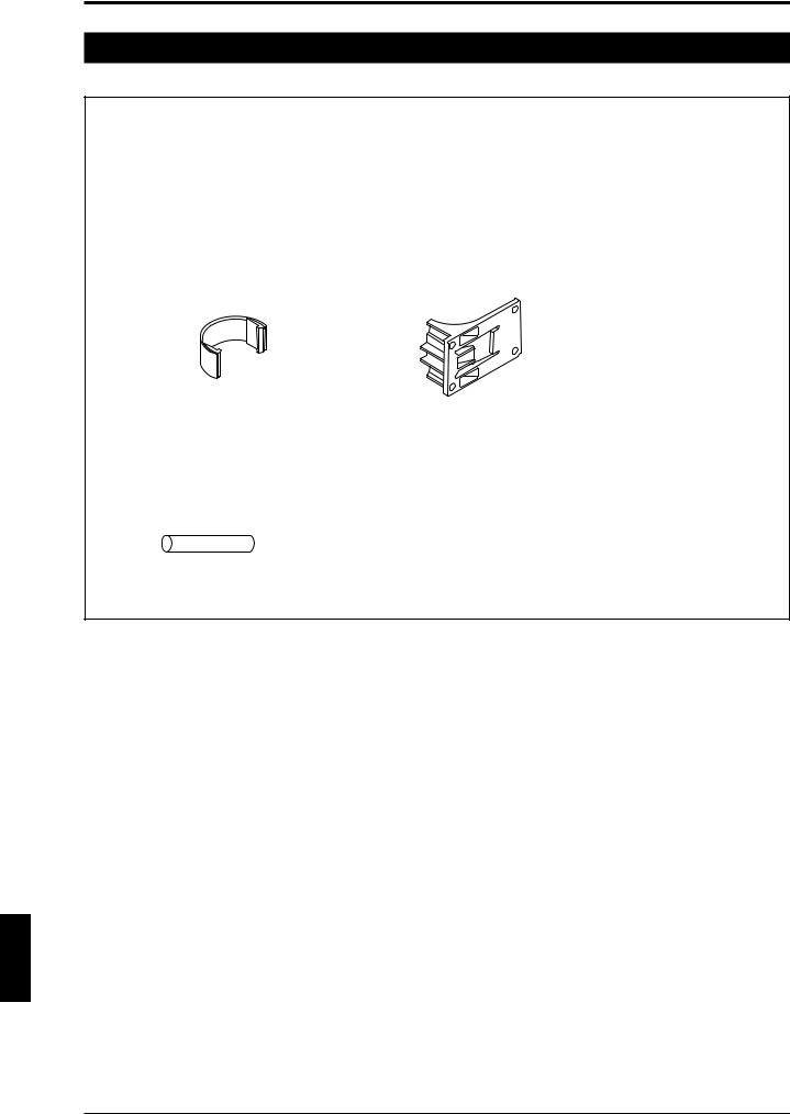
Confirm that the package includes the main unit and the following accessories.
■Accessories
•Intermediate support bracket for installation
*Two pieces of supports are supplied with models SL-C72F through SL-C96F. Four pieces of supports are supplied with models SL-C104F through SL-C128F.
*Two pieces of supports are supplied with models SL-C36H through SL-C48H. Four pieces of supports are supplied with models SL-C52H through SL-C64H.
*Two pieces of supports are supplied with models SL-C18L through SL-C24L. Four pieces of supports are supplied with models SL-C26L through SL-C32L.
Intermediate support bracket A Intermediate support bracket B
*Two connectors are also available grouped as a set (OP-42373).
*It is not possible to install the SL-C only by using the intermediate support brackets that come with models SL-C72F through SL-C128F, SL-C36H through SL-C64H, SL-C18L through SL-C32L. Use optional mounting brackets along with Intermediate support brackets.
•One test piece (Diameter 14 mm (0.55") for SL-C **F, 25 mm (0.98") for SL-C**H)
*Optional test piece (diameter 45 mm (1.77") should be obtained for use of models SL-C08L through SL-C32L.
•Instruction manual (this document) 1 copy
ENGLISH
vii
Chapter 1 Overview and Specifications
1 Overview and Specifications
1-1 Component Names and Units
This section describes each part of the SL-C Series and optional units.
For component locations and appearances, see the “1-4 Dimensional Drawings” (page 1-5).
In this manual, "SL-C Series" means all of the models of SL-C. "SL-C**F" means only the models that have the detection capability of 14 mm (0.55"). "SL-C**H" means only the models that have the detection capability of 25 mm (0.98"), while "SL-C**L" means those that have the detection capability of 45 mm (1.77").
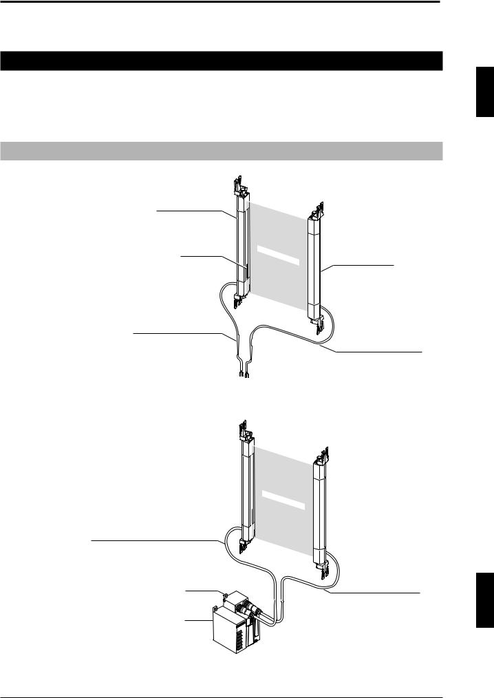
1-1-1 Main System and Cables
When using the SL-C stand-alone
T: Transmitter
R: Receiver
SL-C Series Transmitter
Status indicator |
Detection |
zone |
|
|
|
||
(on both sides) |
|
SL-C Series Receiver |
SL-P7N/P (7 m (22.97 ft.)) cable for transmitter (gray)
SL-P7N/P (7 m (22.97 ft.)) cable for receiver (black)
When combining the SL-C with a controller
SL-C Series + SL-U2 (Dedicated power supply unit) + SL-R11 (Intelligent safety relay unit)
SL-PC5P (5 m (16.4 ft.)) cable for transmitter (gray) * 10 m(32.81 ft.) SL-PC10P cable
SL-R11
SL-U2
Detection |
zone |
|
SL-PC5P (5 m(16.4 ft.)) cable for receiver (black)
* 10 m(32.81 ft.) SL-PC10P cable
SL-U2: The UL certified or recommended dedicated power supply unit
SL-R11:The safety relay is built-in. This is connected to the SL-C by a special connector.
1
ENGLISH
1-1
Chapter 1 Overview and Specifications
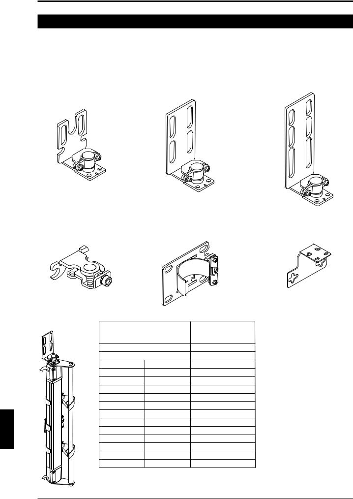
1-2 Mounting Brackets and Cables
This section offers an explanation of safety light curtain mounting brackets and cables. Mounting brackets and cables are optional equipment for the SL-C.
1 |
|
|
|
|
|
1-2-1 Mounting Brackets |
|
||
|
|
Normal mounting bracket A |
Normal mounting bracket B |
Normal mounting bracket C |
|
|
OP-42347 (1 set of 2 brackets) |
OP-42348 (1 set of 2 brackets) |
OP-42349 (1 set of 2 brackets) |
ENGLISH
Includes 6 M3 screws (R=7). |
Includes 6 M3 screws (R=7). |
Includes 6 M3 screws (R=7). |
Thin type mounting bracket |
E-to-E mounting bracket |
L-shaped mounting bracket |
OP-51698 |
OP-42370 (1 set of 2 brackets) |
OP-42371 (1 set of 2 brackets) |
Includes 3 M3 screws |
|
Includes 6 M3 flathead screws |
(R=7). |
|
(small head) (R=5). |
Protection bar |
|
Applicable Model |
|
|
|
SL-C Series Model |
of protection bar |
|
|
|
to SL-C Series |
SL-C08H |
OP-42350 |
|
SL-C12H |
OP-42351 |
|
SL-C16H |
SL-C08L |
OP-42352 |
SL-C20H |
SL-C10L |
OP-42353 |
SL-C24H |
SL-C12L |
OP-42354 |
SL-C28H |
SL-C14L |
OP-42355 |
SL-C32H |
SL-C16L |
OP-42356 |
SL-C36H |
SL-C18L |
OP-42357 |
SL-C40H |
SL-C20L |
OP-42358 |
SL-C44H |
SL-C22L |
OP-42359 |
SL-C48H |
SL-C24L |
OP-42360 |
SL-C52H |
SL-C26L |
OP-42361 |
SL-C56H |
SL-C28L |
OP-42362 |
SL-C60H |
SL-C30L |
OP-42363 |
SL-C64H |
SL-C32L |
OP-42364 |
* The protection bar cannot be used combined with the SL-C**F and the thin type mounting bracket (OP-51698).
1-2
Chapter 1 Overview and Specifications
1-2-2 Cables
SL-C plug - bare wires
34
(1.34")
SL-C plug - M12 connector
SL-P7N (NPN Type 7 m (22.97 ft.))
SL-P15N (NPN Type 15 m (49.21 ft.))
SL-P7P (PNP Type 7 m (22.97 ft.))
ø6 |
(Transmitter/receiver set) |
1 |
|
SL-PC5N (NPN 5 m (16.4 ft.))
SL-PC5P (PNP 5 m (16.4 ft.))
SL-PC10P (PNP 10 m (32.81 ft.))
(Transmitter/receiver set)
ø6
 47 (1.85")


 ø14
ø14
M12 connector - M12 connector SL-CC10NT (NPN 10 m (32.81 ft.) Transmitter),
SL-CC10NR (NPN 10 m (32.81 ft.) Receiver),
SL-CC10PT (PNP 10 m (32.81 ft.) Transmitter),
SL-CC10PR (PNP 10 m (32.81 ft.) Receiver)
41.5 (1.63") |
|
ø6 |
|
ø14
M12 connector-bare wires |
|
|
|
|
|
|
SL-C5N (NPN 5 m (16.4 ft.)) |
||||||||
|
|
|
|
|
|
|
|
|
|
|
|
|
SL-C5P (PNP 5 m (16.4 ft.)) |
||
|
|
|
|
|
|
|
|
|
|
|
|
|
|
|
(Transmitter/receiver set) |
|
|
|
|
|
|
|
ø6 |
||||||||
|
|
|
|
|
|
|
|
|
|
|
|
|
|
|
|
Series connection cable |
SL-S0 (0.08 m (3.14")) |
|
|
SL-S1 |
(0.15 m (5.91")) |
|
SL-S2 |
(0.5 m (1.64 ft.)) |
|
SL-S3 |
(3 m (9.84 ft.)) |
|
SL-S4 |
(1 m (3.28 ft.)) |
SL-S10 (10 m (32.79 ft.))
ø6 (Transmitter/receiver set)
ENGLISH
1-3

Chapter 1 Overview and Specifications
1-3 Specifications
Specifications (Detection capability of 14 mm (0.55") diameter type)
|
|
Model |
|
SL-C16F |
SL-C24F |
SL-C32F |
SL-C40F |
SL-C48F |
SL-C56F |
SL-C64F |
SL-C72F |
||
|
|
||||||||||||
1 |
|
No. of beam axes |
16 |
|
24 |
|
32 |
40 |
48 |
56 |
64 |
72 |
|
|
Detection capability |
|
|
ø14 mm (0.55") (when the blanking function is not used) |
|
||||||||
|
Beam Axis Pitch/Lens Diameter |
|
|
|
|
10 mm (0.39") / ø4 mm (0.15") |
|
|
|||||
|
|
Detection zone |
150 mm (5.90") |
230 mm (9.05") |
310 mm (12.20") |
390 mm (15.35") |
470 mm (18.50") |
550 mm (21.65") |
630 mm (24.80") |
710 mm (27.95") |
|||
|
|
Protection zone |
174 mm (6.85") |
254 mm (10.00") |
334 mm (13.15") |
414 mm (16.30") |
494 mm (19.45") |
574 mm (22.60") |
654 mm (25.75") |
734 mm (28.90") |
|||
|
|
Current |
Transmitter |
61 mA |
67 mA |
73 mA |
79 mA |
85 mA |
91 mA |
97 mA |
103 mA |
||
|
|
consump- |
|
|
|
|
|
|
|
|
|
|
|
|
|
Receiver |
66 mA |
69 mA |
73 mA |
76 mA |
80 mA |
83 mA |
87 mA |
90 mA |
|||
|
|
tion |
|||||||||||
|
|
Weight |
Transmitter |
Approx. 180 g |
Approx. 230 g |
Approx. 285 g |
Approx. 335 g |
Approx. 395 g |
Approx. 440 g |
Approx. 490 g |
Approx. 540 g |
||
|
|
Receiver |
Approx. 195 g |
Approx. 255 g |
Approx. 310 g |
Approx. 370 g |
Approx. 425 g |
Approx. 480 g |
Approx. 540 g |
Approx. 595 g |
|||
|
|
|
|||||||||||
|
|
|
|
|
|
|
|
|
|
|
|
|
|
|
|
Model |
|
SL-C80F |
|
SL-C88F |
|
SL-C96F |
SL-C104F |
SL-C112F |
SL-C120F |
SL-C128F |
|
|
|
No. of beam axes |
80 |
|
88 |
|
96 |
104 |
112 |
120 |
128 |
|
|
|
|
Detection capability |
|
|
ø14 mm (0.55") (when the blanking function is not used) |
|
|
||||||
|
|
Beam Axis Pitch/Lens Diameter |
|
|
|
|
10 mm (0.39") / ø4 mm (0.15") |
|
|
|
|||
|
|
Detection zone |
790 mm (31.10") |
|
870 mm (34.25") |
|
950 mm (37.40") |
1030 mm (40.55") |
1110 mm (43.70") |
1190 mm (46.85") |
1270 mm (50.00") |
|
|
|
|
Protection zone |
814 mm (32.05") |
|
894 mm (35.20") |
|
974 mm (38.35") |
1054 mm (41.50") |
1134 mm (46.65") |
1214 mm (47.80") |
1294 mm (50.94") |
|
|
|
|
Current |
Transmitter |
109 mA |
|
115 mA |
|
121 mA |
127 mA |
133 mA |
139 mA |
145 mA |
|
|
|
consump- |
|
|
|
|
|
|
|
|
|
|
|
|
|
Receiver |
94 mA |
|
97 mA |
|
100 mA |
104 mA |
107 mA |
111 mA |
114 mA |
|
|
|
|
tion |
|
|
|
||||||||
|
|
Weight |
Transmitter |
Approx. 590 g |
Approx. 645 g |
Approx. 695 g |
Approx. 745 g |
Approx. 800 g |
Approx. 850 g |
Approx. 900 g |
|
||
|
|
Receiver |
Approx. 655 g |
Approx. 710 g |
Approx. 765 g |
Approx. 825 g |
Approx. 880 g |
Approx. 940 g |
Approx. 995 g |
|
|||
|
|
|
|
||||||||||
Specifications (Detection capability of 25 mm (0.98") diameter type)
Model |
|
SL-C08H |
SL-C12H |
SL-C16H |
SL-C20H |
SL-C24H |
SL-C28H |
SL-C32H |
SL-C36H |
|||
No. of beam axes |
8 |
|
12 |
|
16 |
20 |
24 |
28 |
32 |
36 |
||
Detection capability |
|
|
ø25 mm (0.98") (when the blanking function is not used) |
|
||||||||
Beam Axis Pitch/Lens Diameter |
|
|
|
|
20 mm (0.79") / ø5 mm (0.19") |
|
|
|||||
Detection zone |
140 mm (5.51") |
220 mm (8.66") |
300 mm (11.81") |
380 mm (14.96") |
460 mm (18.11") |
540 mm (21.26") |
620 mm (24.41") |
700 mm (27.56") |
||||
Protection zone |
185 mm (7.28") |
265 mm (10.43") |
345 mm (13.58") |
425 mm (16.73") |
505 mm (19.88") |
585 mm (23.03") |
665 mm (26.18") |
745mm (29.33") |
||||
Current |
Transmitter |
55 mA |
58 mA |
61 mA |
62 mA |
68 mA |
71 mA |
74 mA |
77 mA |
|||
consump- |
|
|
|
|
|
|
|
|
|
|
|
|
Receiver |
67 mA |
69 mA |
71 mA |
73 mA |
76 mA |
78 mA |
81 mA |
83 mA |
||||
tion |
||||||||||||
Weight |
Transmitter |
Approx. 165 g |
Approx. 210 g |
Approx. 255 g |
Approx. 300 g |
Approx. 345 g |
Approx. 390 g |
Approx. 435 g |
Approx. 480 g |
|||
Receiver |
Approx. 180 g |
Approx. 230 g |
Approx. 280 g |
Approx. 330 g |
Approx. 380 g |
Approx. 430 g |
Approx. 480 g |
Approx. 530 g |
||||
|
||||||||||||
|
|
|
|
|
|
|
|
|
||||
Model |
|
SL-C40H |
SL-C44H |
SL-C48H |
SL-C52H |
SL-C56H |
SL-C60H |
SL-C64H |
|
|||
No. of beam axes |
40 |
|
44 |
|
48 |
52 |
56 |
60 |
64 |
|
||
Detection capability |
|
|
ø25 mm (0.98") (when the blanking function is not used) |
|
|
|||||||
Beam Axis Pitch/Lens Diameter |
|
|
|
|
20 mm (0.79") / ø5 mm (0.19") |
|
|
|
||||
Detection zone |
780 mm (30.71") |
|
860 mm (33.86") |
|
940mm (37.01") |
1020 mm (40.16") |
1100 mm (43.31") |
1180 mm (46.46") |
1260 mm (49.61") |
|
||
Protection zone |
825 mm (32.48") |
|
905 mm (35.63") |
|
985 mm (38.78") |
1065 mm (41.92") |
1145 mm (45.08") |
1225 mm (48.23") |
1305 mm (51.38") |
|
||
Current |
Transmitter |
81 mA |
|
84 mA |
|
87 mA |
91 mA |
94 mA |
97 mA |
100 mA |
|
|
consump- |
|
|
|
|
|
|
|
|
|
|
|
|
Receiver |
86 mA |
|
88 mA |
|
90 mA |
93 mA |
95 mA |
97 mA |
100 mA |
|
||
tion |
|
|
|
|||||||||
Weight |
Transmitter |
Approx. 525 g |
Approx. 570 g |
Approx. 615 g |
Approx. 660 g |
Approx. 705 g |
Approx. 750 g |
Approx. 860 g |
|
|||
Receiver |
Approx. 575 g |
Approx. 625 g |
Approx. 675 g |
Approx. 725 g |
Approx. 775 g |
Approx. 825 g |
Approx. 945 g |
|
||||
|
|
|||||||||||
ENGLISH
1-4

Chapter 1 Overview and Specifications
Specifications (Detection capability of 45 mm (1.77") diameter type)
Model |
|
SL-C08L |
SL-C10L |
SL-C12L |
SL-C14L |
SL-C16L |
SL-C18L |
SL-C20L |
SL-C22L |
|||
No. of beam axes |
8 |
|
10 |
|
12 |
14 |
16 |
18 |
20 |
22 |
||
Detection capability |
|
|
|
|
|
ø45 mm (1.77") |
|
|
|
|||
Beam Axis Pitch/Lens Diameter |
|
|
|
|
40 mm (1.57") / ø5 mm (0.19") |
|
|
|||||
Detection zone |
280 mm (11.02") |
360 mm (14.17") |
440 mm (17.32") |
520 mm (20.47") |
600 mm (23.62") |
680mm (26.77") |
760 mm (29.92") |
840 mm (33.07") |
||||
Protection zone |
365 mm (14.37") |
445 mm (17.52") |
525 mm (20.67") |
605 mm (23.82") |
685 mm (26.97") |
765 mm (30.12") |
845 mm (33.27") |
925 mm (36.42") |
||||
Current |
Transmitter |
55 mA |
57 mA |
58 mA |
60 mA |
61 mA |
62 mA |
62 mA |
65 mA |
|||
consump- |
|
|
|
|
|
|
|
|
|
|
|
|
Receiver |
67 mA |
68 mA |
69 mA |
70 mA |
71 mA |
72 mA |
73 mA |
75 mA |
||||
tion |
||||||||||||
Weight |
Transmitter |
Approx. 255 g |
Approx. 300 g |
Approx. 345 g |
Approx. 390 g |
Approx. 435 g |
Approx. 480 g |
Approx. 525 g |
Approx. 570 g |
|||
Receiver |
Approx. 280 g |
Approx. 330 g |
Approx. 380 g |
Approx. 430 g |
Approx. 480 g |
Approx. 530 g |
Approx. 575 g |
Approx. 625 g |
||||
|
||||||||||||
|
|
|
|
|
|
|
|
|
||||
Model |
|
SL-C24L |
SL-C26L |
SL-C28L |
SL-C30L |
SL-C32L |
|
|
|
|||
No. of beam axes |
24 |
|
26 |
|
28 |
30 |
32 |
|
|
|
||
Detection capability |
|
|
ø45 mm (1.77") |
|
|
|
|
|||||
Beam Axis Pitch/Lens Diameter |
|
|
40 mm (1.57") / ø5 mm (0.19") |
|
|
|
|
|||||
Detection zone |
920 mm (36.22") |
1000 mm (39.37") |
1080 mm (42.52") |
1160 mm (45.67") |
1240 mm (48.82") |
|
|
|
||||
Protection zone |
1005 mm (39.57") |
1085 mm (42.72") |
1165 mm (45.87") |
1245 mm (49.02") |
1325 mm (53.17") |
|
|
|
||||
Current |
Transmitter |
68 mA |
|
70 mA |
|
71 mA |
73 mA |
74 mA |
|
|
|
|
consump- |
|
|
|
|
|
|
|
|
|
|
|
|
Receiver |
76 mA |
|
77 mA |
|
78 mA |
80 mA |
81 mA |
|
|
|
||
tion |
|
|
|
|
|
|||||||
Weight |
Transmitter |
Approx. 615 g |
Approx. 660 g |
Approx. 705 g |
Approx. 750 g |
Approx. 860 g |
|
|
|
|||
Receiver |
Approx. 675 g |
Approx. 725 g |
Approx. 775 g |
Approx. 825 g |
Approx. 945 g |
|
|
|
||||
|
|
|
|
|||||||||
The blanking and muting functions of SL-R12EX cannot be used with SL-C**L (detection capability of 45 mm diameter type).
1
ENGLISH
1-5

Chapter 1 Overview and Specifications
Common specifications
|
|
Model |
|
|
SL-C Series |
|
|
|
|||
1 |
|
SL-C**F Operating distance |
0.1 to 7 m |
||
|
SL-C**H/SL-C**L Operating distance |
0.3 to 9 m |
|||
|
Effective Aperture Angle |
Max. ±2.5° (When operating distance is 3 m (9.84 ft.) or more) |
|||
|
|
Response time |
15 ms*1 |
||
|
|
Light source |
Infrared LED (850 nm) |
||
|
|
Operation form |
Turns on when light is received from all light beams (except when the blanking function is used) |
||
|
|
Rating |
Power voltage |
24V DC ±10% (Ripple P-P 10% or less) |
|
|
|
|
Output type |
2 outputs each for PNP and NPN, Can be changed using the connector cable |
|
|
|
|
Max. load current |
300 mA*2 |
|
|
|
OSSD |
OFF-state voltage |
2.5 V (with a cable length of 7 m (22.97 ft.)) |
|
|
|
Output |
Leakage current |
Max. 100 µA*3 |
|
|
|
|
Max. capacitive load |
0.47 µF (with a load resistance of 100 Ω) |
|
|
|
|
Load wiring resistance |
Max. 2.5 Ω*4 |
|
|
|
|
Protective structure |
IP65 (IEC60529) |
|
|
|
Environ- |
Ambient temperature |
-10°C to 55°C (No frost) |
|
|
|
Storage ambient temperature |
-10°C to 60°C (No frost) |
||
|
|
mental |
|||
|
|
Relative humidity |
35 % to 85 %RH (No condensation) |
||
|
|
specifica- |
|||
|
|
Storage ambient humidity |
35 % to 95 % |
||
|
|
tions |
|||
|
|
Ambient light |
White incandescent lamp: 5,000rx or less Sunlight: 20,000rx or less |
||
|
|
|
|||
|
|
|
Vibration |
10 to 55 Hz, 0.7 mm compound amplitude, 20 sweeps each in X, Y, and Z directions |
|
|
|
|
Shock |
100 m/s2 (Approx. 10G) 16ms pulse, in X, Y, Z directions 1,000 times each axis |
|
|
|
|
Main unit case |
Aluminum |
|
|
|
Material |
Upper case/Lower case |
Zinc die-cast |
|
|
|
|
Overlay |
Polycarbonate |
|
|
|
|
EMC |
EMS |
UL61496-1 |
|
|
Approved |
EMI |
FCC Part15 Class A |
|
|
|
|
|||
|
|
|
|
UL61496-1 (type 4 ESPE) |
|
|
|
standards |
|
|
|
|
|
Safety |
UL61496-2 (type 4 AOPD) |
||
|
|
|
|||
|
|
|
|
|
UL508 |
*1 OFF ON return time is 125 ms.
*2 Note the derating illustrated in the graph to the right when using PNP output.
*3 Includes when the SL-C Series power supply is OFF or when there is a disconnection in the power supply line.
*4 In order to guarantee the proper operation of the SL-C safety circuit, the wiring resistance (excluding dedicated cable wiring resistance) of the cabling connected to the hardware to which the OSSD output and OSSD input are connected must be 2.5 Ω or less. For NPN output type cable, do not let wiring resistance exceed a maximum of 1.0 Ω when the cable length is 15 m (49.21 ft.) or greater and the load current is 200 mA or higher.
(mA) |
|
|
|
|
|
|
300 |
|
|
|
|
|
|
200 |
|
|
|
|
|
|
100 |
|
|
|
|
|
|
0 |
10 |
20 |
30 |
40 |
50 |
(°C) |
ENGLISH
1-6

Chapter 1 Overview and Specifications
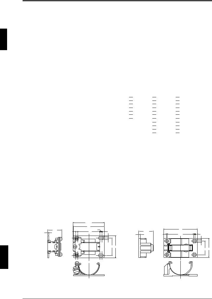
1-4 Dimensional Drawings
With the E-to-E mounting bracket (OP-42370) installed
27.9 |
26.4 |
10.6
SL-C**F
50.4
28
7
5 
D
28
1 38.5
10.5
2 3.5
B |
20 A |
3 |
36 |
|
|
3 |
11 |
|
4 |
|
|
|
28 |
|
|
C |
|
|
D |
|
|
5 |
|
|
7 |
3-M3 |
12 |
4.5 |
|
||
Depth:4.5 |
|
|
|
|
14 |
27.9 |
26.4 |
10.6
15.5
|
SL-C**H |
|
|
50.4 |
|
|
28 |
|
|
|
17.5 |
|
|
5 |
|
|
D |
|
|
28 |
1 |
38.5 |
|
|
|
|
|
2 |
10.5 |
|
3.5 |
|
|
|
|
B |
|
20 A |
3 |
36 |
|
|
11 |
|
|
3 |
4 |
|
|
|
|
|
28 C |
|
|
D |
|
|
5 |
|
|
17.5 |
3-M3 |
12 |
4.5 |
|
Depth:4.5
14
15.5
|
|
|
|
SL-C**F |
|
|
|
|
|
39.7 |
|
|
|
|
|
28 |
3.5 |
|
26.4 |
14.6 |
|
|
|
|
|
|
|
|
7 |
|
|
|
|
|
5 |
|
|
|
D |
|
|
|
|
|
28 |
|
|
1 |
38.5 |
|
|
|
|
|
|
14.5 |
|
|
|
|
|
2 |
3.5 |
|
|
|
|
|
20 |
B |
A |
3 |
36 |
|
|
|
|
|
|
15 |
|
|
|
|
|
3 |
4 |
|
|
|
28 |
|
C |
|
50.4 |
|
D |
|
5 |
10.6 |
7 |
|

 17.5 8


|
|
|
|
SL-C**H |
|
|
|
|
|
39.7 |
|
|
|
14.6 |
|
28 |
3.5 |
|
26.4 |
|
|
|
|
|
|
|
|
17.5 |
|
|
|
|
|
|
|
|
|
|
|
|
5 |
|
|
|
D |
|
|
|
|
|
28 |
|
|
1 |
38.5 |
14.5 |
|
|
|
|
|
|
|
|
|
|
|
2 |
3.5 |
|
|
|
|
|
|
|
|
|
|
|
20 |
B |
A |
|
|
|
|
||
3 |
36 |
15 |
|
|
|
|
|
|
|
|
|
|
|
3 |
4 |
|
|
|
|
|
|
|
|
|
|
|
28 |
|
|
|
|
|
C |
|
|
|
|
50.4 |
|
|
|
|
|
|
D |
|
|
|
|
|
|
|
5 |
10.6 |
|
|
|
|
17.5 |
8 |
|
|
17.5 |
|
|
|
|
|
|
|
(Unit: mm)
|
SL-C**L |
|
|
50.4 |
|
|
28 |
|
|
|
17.5 |
|
|
25 |
|
|
D |
|
|
28 |
1 |
38.5 |
|
|
10.5 |
|
|
|
|
|
|
3.5 |
|
|
A |
B |
|
20 |
|
|
|
3 |
36 |
|
|
11 |
|
|
3 |
4 |
|
|
|
|
|
28 |
|
|
C |
|
|
D |
|
|
5 |
|
|
37.5 |
3-M3 |
12 |
4.5 |
|
||
Depth:4.5 |
|
|
|
|
14 |
|
15.5 |
|
|
SL-C**L |
|
|
39.7 |
|
|
28 |
3.5 |
|
|
17.5 |
|
|
25 |
|
|
A |
B |
|
|
|
|
5 |
|
|
37.5 |
1
ENGLISH
1-7
1
ENGLISH
Chapter 1 Overview and Specifications
Dimensions by model
Model |
No. of beam axes |
Sensor length A |
Detection zone B |
Intermediate support |
Intermediate support |
Intermediate support |
D |
|||||||
bracket position C* |
bracket position C1* |
bracket position C2* |
||||||||||||
|
|
|
|
|
||||||||||
SL-C16F |
16 |
160 (6.30") |
150 (5.91") |
|
|
|
|
|
|
|
|
|
45 (1.77") |
|
|
|
|
|
|
|
|
|
|
||||||
SL-C24F |
24 |
240 (9.45") |
230 (9.06") |
|
|
|
|
|
|
|
|
|
45 to 66 (1.77" to 2.60") |
|
|
|
|
|
|
|
|
|
|
||||||
SL-C32F |
32 |
320 (12.60") |
310 (12.20") |
|
|
|
|
|
|
|
|
|
45 to 93 (1.77" to 3.66") |
|
|
|
|
|
|
|
|
|
|
||||||
SL-C40F |
40 |
400 (15.75") |
390 (15.35") |
|
|
|
|
|
|
|
|
|
45 to 119 (1.77" to 4.69") |
|
|
|
|
|
|
|
|
|
|
||||||
SL-C48F |
48 |
480 (18.90") |
470 (18.50") |
|
|
|
|
|
|
|
|
|
45 to 146 (1.77" to 5.75") |
|
|
|
|
|
|
|
|
|
|
||||||
SL-C56F |
56 |
560 (22.05") |
550 (21.65") |
|
|
|
|
|
|
|
|
|
45 to 173 (1.77" to 6.81") |
|
|
|
|
|
|
|
|
|
|
||||||
SL-C64F |
64 |
640 (25.20") |
630 (24.80") |
|
|
|
|
|
|
|
|
|
45 to 199 (1.77" to 7.83") |
|
|
|
|
|
|
|
|
|
|
||||||
SL-C72F |
72 |
720 (28.35") |
710 (27.95") |
350±80 (13.78"±3.15") |
|
|
|
|
|
|
|
|||
|
|
|
|
|
|
|
||||||||
SL-C80F |
80 |
800 (31.50") |
790 (31.10") |
390±80 (15.35"±3.15") |
|
|
|
|
|
|
|
|||
|
|
|
|
|
|
|
||||||||
SL-C88F |
88 |
880 (34.65") |
870 (34.25") |
430±80 (16.93"±3.15") |
|
|
|
|
|
|
|
|||
|
|
|
|
|
|
|
||||||||
SL-C96F |
96 |
960 (37.80") |
950 (37.40") |
470±80 (18.50"±3.15") |
|
|
|
|
|
|
45 to 200 (1.77" to 7.87") |
|||
|
|
|
|
|
|
|||||||||
SL-C104F |
104 |
1040 (40.94") |
1030 (40.55") |
510±80 (20.08"±3.15") |
337±80 (13.27"±3.15") |
683±80 (26.89"±3.15") |
||||||||
SL-C112F |
112 |
1120 (44.09") |
1110 (43.70") |
550±80 (21.65"±3.15") |
363±80 (14.29"±3.15") |
737±80 (29.02"±3.15") |
|
|||||||
SL-C120F |
120 |
1200 (47.24") |
1190 (46.85") |
590±80 (23.23"±3.15") |
390±80 (15.35"±3.15") |
790±80 (31.10"±3.15") |
|
|||||||
SL-C128F |
128 |
1280 (50.39") |
1270 (50.00") |
630±80 (24.80"±3.15") |
417±80 (16.42"±3.15") |
843±80 (33.19"±3.15") |
|
|||||||
Model |
No. of beam axes |
Sensor length A |
Detection zone B |
Intermediate support |
Intermediate support |
Intermediate support |
D |
|
bracket position C* |
bracket position C1* |
bracket position C2* |
||||||
|
|
|
|
|
||||
SL-C08H |
8 |
150 (5.91") |
140 (5.51") |
|
|
|
43 (1.69") |
|
SL-C12H |
12 |
230 (9.06") |
220 (6.66") |
|
|
|
43 to 63 (1.69" to 2.48") |
|
SL-C16H |
16 |
310 (12.20") |
300 (11.81") |
|
|
|
43 to 89 (1.69" to 3.50") |
|
SL-C20H |
20 |
390 (15.35") |
380 (14.96") |
|
|
|
43 to 116 (1.69" to 4.57") |
|
SL-C24H |
24 |
470 (18.50") |
460 (18.11") |
|
|
|
43 to 143 (1.69" to 5.63") |
|
SL-C28H |
28 |
550 (21.65") |
540 (21.56") |
|
|
|
43 to 169 (1.69" to 6.65") |
|
SL-C32H |
32 |
630 (24.80") |
620 (24.41") |
|
|
|
43 to 196 (1.69" to 7.72") |
|
SL-C36H |
36 |
710 (27.95") |
700 (27.56") |
345±80 (13.58"±3.15") |
|
|
|
|
SL-C40H |
40 |
790 (31.10") |
780 (30.71") |
385±80 (15.16"±3.15") |
|
|
|
|
SL-C44H |
44 |
870 (34.25") |
860 (33.86") |
425±80 (16.73"±3.15") |
|
|
|
|
SL-C48H |
48 |
950 (37.40") |
940 (37.01") |
465±80 (18.31"±3.15") |
|
|
43 to 197 (1.69" to 7.76") |
|
SL-C52H |
52 |
1030 (40.55") |
1020 (40.16") |
505±80 (19.88"±3.15") |
333±80 (13.11"±3.15") |
677±80 (26.65"±3.15") |
||
SL-C56H |
56 |
1110 (43.70") |
1100 (43.31") |
545±80 (21.46"±3.15") |
360±80 (14.17"±3.15") |
730±80 (28.74"±3.15") |
|
|
SL-C60H |
60 |
1190 (46.85") |
1180 (46.46") |
585±80 (23.03"±3.15") |
387±80 (15.24"±3.15") |
783±80 (30.83"±3.15") |
|
|
SL-C64H |
64 |
1270 (50.00") |
1260 (49.61") |
625±80 (24.61"±3.15") |
413±80 (16.26"±3.15") |
837±80 (32.95"±3.15") |
|
Model |
No. of beam axes |
Sensor length A |
Detection zone B |
Intermediate support |
Intermediate support |
Intermediate support |
D |
|||||||
bracket position C* |
bracket position C1* |
bracket position C2* |
||||||||||||
|
|
|
|
|
||||||||||
SL-C08L |
8 |
310 (12.20") |
280 (11.02") |
|
|
|
|
|
|
|
|
|
43 to 89 (1.69" to 3.50") |
|
|
|
|
|
|
|
|
|
|
||||||
SL-C10L |
10 |
390 (15.35") |
360 (14.17") |
|
|
|
|
|
|
|
|
|
43 to 116 (1.69" to 4.57") |
|
|
|
|
|
|
|
|
|
|
||||||
SL-C12L |
12 |
470 (18.50") |
440 (17.32") |
|
|
|
|
|
|
|
|
|
43 to 143 (1.69" to 5.63") |
|
|
|
|
|
|
|
|
|
|
||||||
SL-C14L |
14 |
550 (21.65") |
520 (20.47") |
|
|
|
|
|
|
|
|
|
43 to 169 (1.69" to 6.65") |
|
|
|
|
|
|
|
|
|
|
||||||
SL-C16L |
16 |
630 (24.80") |
600 (23.62") |
|
|
|
|
|
|
|
|
|
43 to 196 (1.69" to 7.72") |
|
|
|
|
|
|
|
|
|
|
||||||
SL-C18L |
18 |
710 (27.95") |
680 (26.77") |
345±80 (13.58"±3.15") |
|
|
|
|
|
|
|
|||
|
|
|
|
|
|
|
||||||||
SL-C20L |
20 |
790 (31.10") |
760 (29.92") |
385±80 (15.16"±3.15") |
|
|
|
|
|
|
|
|||
|
|
|
|
|
|
|
||||||||
SL-C22L |
22 |
870 (34.25") |
840 (33.07") |
425±80 (16.73"±3.15") |
|
|
|
|
|
|
|
|||
|
|
|
|
|
|
|
||||||||
SL-C24L |
24 |
950 (37.40") |
920 (36.22") |
465±80 (18.31"±3.15") |
|
|
|
|
|
|
43 to 197 (1.69" to 7.76") |
|||
|
|
|
|
|
|
|||||||||
SL-C26L |
26 |
1030 (40.55") |
1000 (39.37") |
505±80 (19.88"±3.15") |
333±80 (13.11"±3.15") |
677±80 (26.65"±3.15") |
||||||||
|
||||||||||||||
SL-C28L |
28 |
1110 (43.70") |
1080 (42.52") |
545±80 (21.46"±3.15") |
360±80 (14.17"±3.15") |
730±80 (28.74"±3.15") |
|
|||||||
SL-C30L |
30 |
1190 (46.85") |
1160 (45.67") |
585±80 (23.03"±3.15") |
387±80 (15.24"±3.15") |
783±80 (30.83"±3.15") |
|
|||||||
SL-C32L |
32 |
1270 (50.00") |
1240 (48.82") |
625±80 (24.61"±3.15") |
413±80 (16.26"±3.15") |
837±80 (32.95"±3.15") |
|
|||||||
*If using the normal mounting brackets A, B, C, or the L-shaped mounting bracket for installing the model that has the sensor length 710 mm (27.95") or more, use of two intermediate support brackets is required. For such installation, attach intermediate support brackets at dimensional positions C1 and C2. For other installations, attach one intermediate support bracket at dimensional position C.
E-to-E mounting bracket |
|
(50.4) |
|
Intermediate support brackets (OP-42373) |
||||
(OP-42370) |
|
50 |
|
|
|
|
|
|
(24) |
|
3 |
|
|
|
49 |
|
|
|
4 |
|
|
(21.2) |
|
|
||
1.5 |
3 |
36 |
|
|
|
2 |
|
|
|
|
|
2.5 |
1 |
38.5 |
3.5 |
|
|
|
|
|
|
|
||||
|
|
5 |
|
|
|
|
|
|
|
|
28 |
36 |
|
|
|
4.5 |
|
|
|
|
|
|
|
|
20 |
28 |
1-8
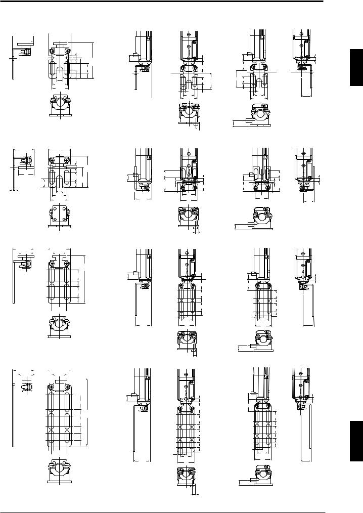
Chapter 1 Overview and Specifications
Normal mounting bracket A, |
With Normal mounting bracket A installed |
outward-facing (OP-42347) |
|
 27.5 (1.08")
 21(0.83")


 2(0.08")
 29 (1.14")
 18(0.71")
5 (0.2")
(46.5) (0.42")10.6
(1.83")
27 (1.06") 12
(0.47")
(0.31") |
|
7.5 |
||
|
8 |
11.5 |
(0.3") |
|
19 |
(0.75") |
|||
(0.45") |
|
|||
22 (0.87") |
|
|||
|
|
|||
 27.9
27.9  (1.1")
|
|
5 (0.2") |
|
|
(19.5)(0.77") |
|
|
(0.47") |
|
|
27 |
|
|
12 (1.06") |
(0.24")6 |
(0.75") |
7.5 |
|
19 |
(0.3") |
|
29(1.14") |
|
(0.42")10.6 |
|
|
|
(0.77")(19.5) |
|
||
|
(0.47") |
|
|
(1.06")27 |
12 |
|
|
(0.3") 7.5 |
6 |
(0.75") |
|
|
(0.24") |
19 |
|
|
|
|
29(1.14") |
5 (0.2")
(0.69")
17.5
|
|
(0.31") |
8 |
|
(0.2") |
5 |
|
Normal mounting bracket A, |
With Normal mounting bracket A installed |
||
inward-facing (OP-42347) |
|
|
|
27.5 |
|
29 |
|
|
(1.08") |
|
(1.14") |
|
|
|
|
(0.2") |
|
|
|
|
5 |
(41.3) |
|
|
|
|
(1.63") |
|
21 |
|
12 (0.47")27 |
|
|
(0.83") |
|
10.6 |
||
|
(0.45")11.5 |
(1.06") |
(0.42") |
|
|
7.5 |
|
|
|
|
|
|
|
|
2(0.08") |
8(0.31") |
(0.3") |
19(0.75") |
27.9 |
22(0.87") |
|
|
(1.1") |
12 (0.47") |
|
|
|
12(0.47") |
|
|
(21.8) |
5 |
5 (0.2") |
(0.42")10.6 |
|
5(0.2") |
5 (0.2") |
|
|
|
|
|||
(0.86") (0.2") |
16.5 (0.65") |
(0.65")16.5 |
|
(21.8(0.86")) |
|
|
|
(14.3) |
22 |
|
|
(14.3) |
|
|
(0.56") |
(0.87") |
|
22 |
(0.56") |
17.5 |
|
|
29 |
|
(0.87") |
(0.86") |
|
|
|
(1.14") |
|
|
(0.69") |
|
|
|
|
|
|
|
|
|
(0.31") |
8 |
|
5 (0.2") |
|
Normal mounting bracket B (OP-42348) |
With Normal mounting bracket B installed |
|
27.5 (1.08") |
|
|
|
29 (1.14") |
|||||
|
21(0.83") |
|
|
|
18(0.71") |
||||
|
|
|
|
|
|
|
|
|
|
|
|
|
|
|
|
|
|
|
|
|
|
|
|
|
|
|
|
|
|
(62.5)
(2.46")
14.5
(0.57")
7.5 (0.3")
14.5 (0.57")
7.5 (0.3")


 2(0.08") (0.24")6


 19
19 
(0.75")
10.6 |
|
5 (0.2") |
(0.42")10.6 |
|
5 (0.2") |
(0.42") |
|
|
|
|
|
|
|
(18.5)(0.72") |
(0.72")(18.5) |
|
|
|
|
14.5 (0.57") |
|
14.5 (0.57") |
|
|
|
7.5 (0.3") |
|
7.5 |
(0.3") |
|
|
14.5 (0.57") |
|
14.5 (0.57") |
|
(0.24") |
|
7.5 (0.3") |
(0.24")6 |
7.5 |
(0.3") |
6 |
19 |
19 |
|
||
|
|
|
|
||
27.9 |
|
(0.75") |
|
(0.75") |
17.5 |
|
29 |
|
29 |
(0.69") |
|
(1.1") |
|
(1.14") |
|
(1.14") |
|
Normal mounting bracket C (OP-42349)
27.5 (1.08") |
|
|
|
|
|
|
|
|
29(1.14") |
|
|
|
|
|
|
||||||||
|
|
21(0.83") |
|
|
|
|
|
|
|
18(0.71") |
|
|
|
|
|
|
|||||||
|
|
|
|
|
|
|
|
|
|
|
|
|
|
|
|
|
|
|
|
|
|
|
|
|
|
|
|
|
|
|
|
|
|
|
|
|
|
|
|
|
|
|
|
|
|
|
|
|
|
|
|
|
|
|
|
|
|
|
|
|
|
|
|
|
|
|
|
|
|
|
|
|
|
|
|
|
|
|
|
|
|
|
|
|
|
|
|
|
|
|
|
|
|
|
|
(0.67")17
(0.31")8 (82.3)  (3.24")
13(0.51")
8 (0.31")
8 (0.31")
7.8 (0.31")


 2(0.08") (0.24")6


 19
19 
(0.75")
(0.31") |
8 |
5 (0.2")
With Normal mounting bracket C installed
10.6 |
(0.42") |
10.6 |
5 (0.2") |
|
5 (0.2") |
|
|
||
(0.42") |
|
|
|
|
|
(0.81")(20.5) |
|
||
|
(20.5)(0.81") |
|
|
|
|
17 (0.67") |
|
|
17 (0.67") |
|
|
|
|
|
|
8(0.31") |
|
|
8(0.31") |
|
|
|
13 (0.51") |
|
|
13 (0.51") |
|
|
|
|
|
|
8 (0.31") |
|
|
8 (0.31") |
|
|
|
|
|
|
8 (0.31") |
|
|
8 (0.31") |
|
|
|
|
|
(0.24")6 |
7.8 (0.31") |
|
|
7.8 (0.31") |
|
|
|
|
(0.24")6 |
|
19 |
|
|
19 |
|
(0.75") |
17.5 |
27.9 |
(0.75") |
|
29 |
|
29 |
|
(1.14") |
(0.69") |
|
(1.1") |
|
|||
(1.14") |
|
|
||
|
(0.31") |
8 |
|
|
|
(0.2") 5 |
|
|
|
1
ENGLISH
1-9
Loading...