


 Loading...
96M11291
DIGITAL FIBER SENSOR
FS-V30/31(P)/31C(P)/31M/32(P)/32C(P)
Instruction Manual
Read this manual before using the product in order to achieve maximum performance. Keep this manual in a safe place after reading it so that it can be used at any time.
Warning |
• This product is just intended to detect the object(s). Do not use this product |
for the purpose to protect a human body or a part of human body. |
•This product is not intended for use as explosion-proof product. Do not use this product in a hazardous location and/or potentially explosive atmosphere.
•This product is a sensor of DC power supply type. Do not apply AC power. The product may explode or burn if an AC voltage is applied.
Precautions on Regulations and Standards
UL Certificate
This product is an UL/C-UL Listed product.
• |
UL File No. |
E301717 |
• |
Category |
NRKH,NRKH7 |
• |
Enclosure |
Type 1 (Based on UL50) |
Be sure to consider the following specifications when using this product as an UL/ C-UL Listed Product.
•Use the power supply with Class 2 output defined in NFPA70 (NEC: National Electrical Code).
•Power supply/ Control input/ Control output circuits shall be connected to a single Class 2 source only.
•Use with the over current protection device which is rated 24V or more and not more than 2A.
Part Names
Fiber lock lever
Operation status indicators
Set button (SET)
|
DSC |
DSC indicator |
Setting value |
DSC |
|
(Displayed in green) |
|||
|
|
|
||
|
|
Digital monitor |
Current value |
|
|
|
|
|
|
|
|
Manual button |
(Displayed in red) |
|
|
|
|
|
|
SEL |
|
Expansion protective cover |
SEL |
|
|
Expansion connector |
|||
|
|
|
||
M |
|
Power selection switch*1 |
M |
|
Mode button
Output selector
 Cable*2
 Dust cover
*1 When set to “M”, the power mode is fixed to Mega Turbo.
*2 FS-V30 does not have the cable. M8 connector for FS-V31C(P)/32C(P)
I/O Circuit |
|
|
|
|
|
|
||
FS-V31/32/31M |
|
|
FS-V31P/32P |
|
||||
circuit |
|
|
Brown *1 |
|
12 to 24 VDC |
circuit |
|
12 to 24 VDC |
mainsensorPhotoelectric |
|
Protection circuit |
Monitor output |
|
mainsensorPhotoelectric |
|
Brown *3 |
|
Overcurrent circuitprotection |
Devices with |
Overcurrent circuitprotection |
|
|||||
(1 to 5 V)*2 |
|
|||||||
|
|
|
Orange |
|
10 kΩ input |
|
|
Max. 100mA |
|
|
|
|
impedance min. |
|
|
||
|
|
|
Max. 100mA |
|
|
Load |
||
|
|
|
|
|
|
|||
|
|
|
|
Load |
|
|
|
Black |
|
|
|
Black |
|
|
|
(Control output) |
|
|
|
|
(Control output) |
|
|
|
Blue *3 |
|
|
|
|
|
|
0 VDC |
|
|
|
|
|
|
Blue *1 |
|
|
|
0 VDC |
|
*1 FS-V31/31M only |
*2 FS-V31M only |
*3 FS-V31P only |
|
|||||
FS-V31C/32C |
|
|
|
|
|
|
||
Output Circuit Diagram |
Input Circuit Diagram |
|
|
|
(1)* |
Sensor main circuit |
|
|
12-24 VDC |
Overcurrent protection circuit |
|
(4) |
|
|
Load |
||
|
(3)* |
||
|
|
|
0 VDC |
Pin assignment |
2 |
4 |
|
1 |
3 |
||
|
|
||
FS-V31CP/32CP
Output Circuit Diagram
|
|
|
(1)* |
Sensor main circuit |
|
|
12-24 VDC |
Overcurrent protection circuit |
|
(4) |
|
|
Load |
||
|
0 VDC |
||
|
|
|
|
|
|
|
(3)* |
Pin assignment |
2 |
4 |
|
1 |
3 |
||
|
|
||
|
DC3.3 V |
|
|
main circuit |
|
(2) |
|
|
PLC, etc. |
||
Sensor |
(Short-circuit current |
||
(3)* |
|||
1 mA or less) |
|||
|
0 VDC |
||
|
|
||
|
|
* FS-V31C only |
Input Circuit Diagram |
|
|
|
|
12-24 VDC |
|
|
(1)* |
circuit |
|
PLC, etc. |
main |
|
|
|
|
|
Sensor |
(Short-circuit |
(2) |
|
|
|
|
current 2 mA |
|
|
or less) |
|
* FS-V31CP only
Socket Cable (Sold Separately)
For FS-V31C(P)/32C(P) |
|
Pin and wire color table |
|
|
OP-73864 |
(cable length:2 m) |
|
Connected pin No. Core wire cover color |
|
OP-73865 |
(cable length:10 m) |
|
||
|
(1) |
Brown |
||
|
4 |
2 |
||
|
|
|
||
|
3 |
1 |
(2) |
White |
|
|
|
(3) |
Blue |
|
|
|
(4) |
Black |
Mounting Unit
Mounting on a DIN Rail
1 Align the claw at the bottom of the main body with the DIN rail. While pushing the main body in the direction of the arrow 1, slant it in the direction of the arrow 2.
2To dismount the sensor, raise the main body in the direction of the arrow 3 while pushing the main body in the direction of the arrow 1.
Installation on a Wall (Main Unit Only)
Attach the unit to the optional mounting bracket (OP-73880), mount them together, and secure them with two M3 screws as shown in the illustration.
OP-73880
Connecting Multiple Amplifiers
Up to 16 sub units can be connected to one main unit.
1 Remove the protection cover on the side of the main unit.
2 Install the amplifier one by one on the DIN rail.
3 Engage the two claws of the child unit with the recesses on the main unit side until you hear a click sound.
4 Attach the end units (option: OP-26751) to the both ends of the connected amplifiers in the same way as in step (2).
5 Sandwich the amplifiers between the end |
|
|
units. Tighten the screws at the top (two |
|
|
screws x two units) with a Phillips screwdriver |
OP-26751 (a set of two) |
|
to fix the end units. |
||
|
Connecting Fiber Unit
1 Open the dust cover in the direction shown by arrow 1.
2 Move down the fiber lock lever in the direction shown by arrow 2.
3 Insert a fiber unit into the fiber insertion holes to a length of the fiber insertion sign (i.e., approximately 14 mm).
4 Move down the fiber lock lever in the |
|
direction shown by arrow 4. |
Fiber insertion sign |
Note
If a thin fiber unit is used, an adapter provided with the thin fiber unit will be required. Unless the right adapter is connected, the thin fiber unit will not detect targets correctly. (The adapter is supplied with the fiber unit.)
Cable outer dia. |
Adapter |
Appearance |
φ1.3 |
Adapter A |
|
(OP-26500) |
|
|
|
|
|
φ1.0 |
Adapter B |
|
(OP-26501) |
|
|
|
|
•To connect the coaxial reflective type fiber unit to the amplifier, connect the single-core fiber to the transmitter side, and connect the multiple-core fiber to the receiver side.
Transmitter
Single-core fiber
Multi-core fiber
Receiver
1
Making Sensitivity Settings
Two-point Calibration
In this mode, the PV used will be the mean value of two sensing values obtained with and without a workpiece.
1 Press the SET button without any workpiece placed in front of the fiber unit.

 DSC
DSC
2 Place a workpiece placed in front of the fiber unit, and press the SET button.
Workpiece |
DSC |
When the setting is completed, the setting value is displayed.
If the sensitivity difference does not have enough room, “ ” flashes for about two seconds after the calibration is complete. The set value is stored in memory even in that case.
Maximum Sensitivity Setting
Set the sensitivity without a workpiece in the case of the reflective type, and with a workpiece in the case of the through-beam or retro-reflective type.
"Reflective model"

 DSC
DSC
"Through-beam model"
3 sec or longer
Press the SET button for three seconds in the state as shown in the above figure. (Release the button when SET flashes.)
When setting the sensitivity, set the value slightly higher than the received light intensity.
Full Auto Calibration
In this mode, the PV will be set to the mean value of the maximum and minimum incident values obtained within a certain period. Use this mode to detect moving workpieces.
1Press the set button for a minimum of three seconds while the target workpiece is passing the sensing area of the fiber unit.
•While the SET button is pressed, the sensitivity of the sensor will be set according to the incident values.
Workpiece |
DSC |
•After the setting is completed, the setting value is displayed on the digital monitor.
Positioning Calibration
1 Press the SET button without any workpiece placed in front of the fiber unit.

 DSC
DSC
2 Place a workpiece on the position where you want to perform positioning.
Workpiece |
DSC |
Head
When the setting is completed, the setting value is displayed.
Press the SET button for 3 seconds or longer until the display flashes.
Fine-adjusting Sensitivity
The setting value can be directly changed by pressing the manual button.

 DSC
DSC
SEL M
M 

When extension display (page 5, No.8) is set for the number of digits to be displayed for the received light intensity
1 Press the manual button quickly once, and check that the setting value flashes.
2 While the setting value is flashing, change the setting value with the Manual button.
Percentage (%) Calibration
This is a calibration method that can set the setting value by percentage with reference to the received light intensity at the time of sensitivity setting.
For example, if the target value is set to –10P, the setting value is determined 10% lower than the received light intensity when the SET button is pressed.
1When selecting the sensitivity setting method (page 4, No. 2), select the % calibration, and set the target value of calibration.
2Taking the desired light intensity as a reference (normally without a workpiece), press the SET button.

 DSC
DSC
SEL M
M 

*While the % calibration is in use, other calibrations (sensitivity setting) cannot be used.
*With FS-V31C(P)/32C(P), by periodically performing external calibration from PLC or other devices, stable detection can be performed even with a small sensitivity difference.
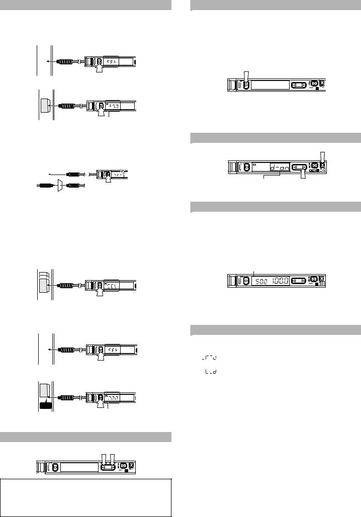
Output Selection
Either light-ON mode or dark-ON mode is selectable.
|
|
(1) Press |
DSC |
|
|
|
SEL |
M |
|
(2) |
|
When the area detection mode is |
Press (2) within five seconds |
|
selected, the selection options are |
after pressing (1). |
|
NO and NC. |
|
|
Dynamic Sensitivity Correction (DSC) Function
DSC automatically corrects the setting value according to the changes in the received light intensity when there is no workpiece (output OFF).
This function is effective when the light intensity difference is small when judging whether or not there is a workpiece.
At Detection mode selection (page 4, No.4), select “Dynamic sensitivity correction mode” beforehand.*
How to set the sensitivity is the same as in the normal mode.
The DSC indicator illuminates when the DSC function is set.
DSC indicator

 DSC
DSC
SEL M
M
*When Light ON is selected, the upper limit of the correctable range is twice as much as the initial setting value.
*The value is stored in memory even after the power is turned off.
*The DSC indicator flashes when the light intensity during output OFF greatly fluctuates or the L/D ON selection is inappropriate. In such a case, check the setting again.
Edge Detection Mode
This mode detects the change in the received light intensity during a given period of time.
|
|
|
Rising edge detection |
Detects the increase (rising edge) of the |
|
|
|
|
received light intensity |
|
|
|
|
|
|
|
|
Falling edge detection |
Detects the decrease (falling edge) of the |
|
|
|
|
received light intensity |
|
|
|
|
|
Filter Setting
Basically, leave this setting as its initial value. If the passage interval of workpieces is too short for the unit to respond, strengthen the level and try again.
The selectable filter level differs depending on the power modes.
Filter level |
HSP* |
FINE |
TURBO |
SUPER |
ULTRA |
MEGA |
|
|
|
|
|
|
|
Default state |
5 |
8 |
9 |
9 |
9 |
9 |
|
|
|
|
|
|
|
Setting range |
1 to 5 |
4 to 8 |
5 to 9 |
6 to 9 |
8 to 9 |
9 only |
|
|
|
|
|
|
|
*HSP: HIGH SPEED
As the number becomes smaller, the filter becomes stronger, which makes the unit difficult to respond to gradual changes in light intensity.
Making Sensitivity Settings
The sensitivity is set to maximum when the SET button is pressed quickly once. When the setting value is too low and the unit detects objects other than the workpiece, fine-adjust the setting value to a higher number.
Operation When Switching Outputs
Setting |
Operation |
|
|
L-ON |
Normally OFF. Turns ON only when the light intensity changes. |
|
|
D-ON |
Normally ON. Turns OFF only when the light intensity changes. |
|
|
2
Loading...