


 Loading...
96M12230
Vision Sensor
IV-500C / IV-500CA / IV-500M / IV-500MA / IV-150M / IV-150MA / IV-2000M / IV-2000MA
Instruction Manual
Read this manual before using the product in order to achieve maximum performance.
Keep this manual in a safe place after reading it so that it can be used at any time.
For details of functions, refer to the IV Series User's Manual (Monitor) or the IV Series User's Manual (PC).
yyThe IV Series User's Manual can be downloaded from the KEYENCE web site:
http://www.keyence.com/
Symbols
The following symbols alert you to important messages. Be sure to read these messages carefully.
It indicates a hazardous situation which, if not avoided, will result in death or serious injury.
It indicates a hazardous situation which, if not avoided, could result in death or serious injury.
It indicates a hazardous situation which, if not avoided, could result in minor or moderate injury.
It indicates a situation which, if not avoided, could result in product damage as well as property damage.
It indicates cautions and limitations that must be followed during operation.
It indicates additional information on proper operation.
It indicates tips for better understanding or useful information.
Cautions
(1)Unauthorized reproduction of this manual in whole or part is prohibited.
(2)The contents of this manual may be changed for improvements without prior notice.
(3)An utmost effort has been made to ensure the contents of this manual are as complete as possible. If there are any mistakes or questions, please contact a KEYENCE office listed in the back of the manual.
(4)Regardless of item (3), KEYENCE will not be liable for any effect resulting from the use of this unit.
(5)Any manuals with missing pages or other paging faults will be replaced.
The company names and product names used in this manual are registered trademarks or the trademarks of their respective companies.
Safety Information for IV series
General Precautions
yyDo not use this product for the purpose to protect a human body or a part of human body.
yyThis product is not intended for use as an explosion-proof product. Do not use this product in a hazardous location and/or potentially explosive atmosphere.
yyYou must verify that the IV Series are operating correctly in terms of functionality and performance before the start and the operation of the IV Series.
yyWe recommend that you take substantial safety measures to avoid any damage in the event of a problem occurring.
yyKEYENCE never warrants the function or performance of the IV Series if it is used in manner that differs from the IV Series specifications contained in this instruction manual or if the IV
Series are modified by yourself.
yyWhen the IV Series is used in combination with other instruments, functions and performance may be degraded, depending on operating conditions and the surrounding environment.
yyDo not place the instruments, including peripherals, under rapid temperature change. It may cause condensation and may damage instruments or peripherals.
yyRemove the power cable from the power supply if you do not use this product for a long time.
Safety precautions on LED product
Use of controls or adjustments or performance of procedures other than those specified herein may result in hazardous radiation exposure. Follow the instructions mentioned in this manual. Otherwise, injury to the human body (eyes and skin) may result.
yyDo not stare into the direct or specularly reflected beam.
yyDo not disassemble this product. The laser radiation emission from this product is not
automatically stopped when it is disassembled. yyDo not direct the beam at people or into
areas where people might be present. yyBe careful of the path of the LED beam. If there is a possibility that the operator
may be exposed to the specular or diffuse reflections, block the beam by installing a protective enclosure.
yyInstall this product so that the path of the LED beam is not as the same height as that of human eye.
Important Instructions
Observe the following precautions to prevent malfunction of the IV Series and to ensure that it is used properly.
Precautions on use
yyThe power of this product and instruments connected to this product must be turned off when the cable is to be installed or removed. Failure to do so may cause an electric shock or a product damage.
yyUse this product in the correct supply voltage. Failure to do so may cause a product damage.
1 |
IV Series (Sensor) - IM_E |
yyFor instructions
yyDo not turn OFF the power while setting the items or saving the settings. Otherwise, all or part of the setting data may be lost.
yyDo not let water, dust or oil stick to the camera/light of the sensor. Failure to do so may cause a malfunction.
yyWhen this product becomes dirty, do not rub it with a wet cloth, benzene, thinner, or alcohol. Doing so may change the color or shape of the unit.
yyIf the unit is heavily contaminated, disconnect all the cables including the power supply cable, wipe off the dirt with a cloth soaked with mild detergent, and then wipe with a soft dry cloth.
yyFor external master image registration
When the external master image registration is used frequently, set "Write ROM when registering external master" of the input option to "No" for nonvolatile memory protection of the internal sensor. When the option is set to "Yes", the nonvolatile memory is guaranteed to write for 100,000 times.
yyFor automatic focus function
yyAutomatic focus function is used for adjusting the focusing position at the time of installation. This will not activate during the operation.
yyFocusing position can be registered in each program. The program configurations are guaranteed to switch for 100,000 times. If the focusing position does not need to change for each program, set "AF Adjustment Pos" to "Common" for extending the life-span. yyDo not apply shock or vibration during the focusing position adjustment . Failure to
do so may cause a product damage.
Measures to be taken when an abnormality occurs
In the following cases, turn the power OFF immediately. Using the IV Series in an abnormal condition could cause fire, electric shock, or malfunction. Contact our office for repair.
yyIf water or debris enters the IV Series.
yyIf the IV Series is dropped or the case is damaged. yyIf abnormal smoke or odor emanates from
the IV Series.
Precautions on installation
yyTo use this product correctly and safely, avoid installing it in the following locations. Failure to do so may cause fire, electric shock, or malfunction. yyOutdoors
yyAltitude above 2000 m
yyLocations that are humid, dusty or poorly ventilated
yyLocations where the temperature is high such as those exposed to direct sunlight yyLocations where there are flammable or
corrosive gases
yyLocations where the unit may be directly subjected to vibration or impact
yyLocations where water, oil, or chemicals may splash onto the unit
yyTo improve the anti-noise feature, install the unit following the precautions below. Otherwise, a malfunction may occur. yyMount the sensor onto the insulated
attached mounting adapter.
yyGround the FG cable (drain cable) of the sensor. yyDo not mount the unit in a cabinet where
high-voltage equipment is already installed. yyMount the unit as far from power lines as possible. yySeparate the unit as far as possible from the devices that emit strong electric or magnetic
field (such as solenoid or chopper). yySeparate the I/O signal line from the power
line or high-voltage line.
yyFor power supply
yyNoise superimposed on the power supply could cause malfunction. Use a stabilized DC power supply configured with an isolation transformer. yyWhen using a commercially available
switching regulator, be sure to ground the frame ground terminal.
yyDevices including this unit are precision components. Do not apply shock or vibration.
yyWhen connecting to a network, let engineers who are knowledgeable about networks handle it.
Precautions on Regulations and Standards
UL Certification
This product is a UL/C-UL Listed product. yyUL File No. E301717
yyCategory NRKH, NRKH7
Be sure to consider the following specifications when using this product as a UL Listed product.
yyUse a power supply with Class 2 output defined in NFPA70
(NEC: National Electrical Code).
yyPower supply/ External input/ Control output shall be connected to a single Class 2 source only.
yyUse with an over current protection device which is rated 24 V or more and not more than 1 A.
yyEnclosure Type 1 (Based on UL50)
CE Marking
Keyence Corporation has confirmed that this product complies with the essential requirements of the applicable
EC Directive, based on the following specifications. Be sure to consider the following specifications when using this product in the Member State of European Union.
zzEMC Directive (2004/108/EC)
yyApplicable Standard EMI: EN60947-5-2, Class A
EMS: EN60947-5-2
yyThe length of power/IO cable, Ethernet cable and Monitor cable must be less than or equal to 30m.
Remarks:
These specifications do not give any guarantee that the end-product with this product incorporated complies with the essential requirements of EMC Directive. The manufacturer of the end-product is solely responsible for the compliance on the end-product itself according to EMC Directive.
zzLow-Voltage Directive (2006/95/EC) yyApplicable Standard: EN62471
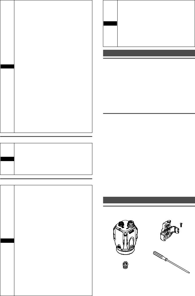
Checking the Package Contents
Sensor
yyIV-500C |
yyIV-150M |
yyIV-500M |
yyIV-2000M |
yyIV-500CA |
yyIV-150MA |
yyIV-500MA |
yyIV-2000MA |
Mounting adapter x 1
Screw for mounting adapter x 1
Sensor x 1
Waterproof cap for Ethernet  connector x 1 Flathead screwdriver x1
(Manual focus type only) Instruction Manual x 1 (This manual)
The mounting adapter is mounted on the monitor in the default factory setting.
IV Series (Sensor) - IM_E |
2 |

Optional parts for sensor
Dome attachment yyIV-D10
|
Mounting screw x 2 |
|
|
Hexagon wrench |
|
Dome attachment x 1 |
(L-shaped) x 1 |
|
Instruction Manual x 1 |
||
|
Polarized visible light filter attachment yyOP-87436
Mounting screw x 2
Instruction Manual x 1
Polarized visible light filter attachment x 1
Infrared polarization filter attachment yyOP-87437
Mounting screw x 2
Instruction Manual x 1
Infrared polarization filter attachment x 1
Power I/O cable (M12 12pin - strand wire)
yyOP-87440 (2m) |
yyOP-87441 (5m) |
yyOP-87442 (10m) |
Power I/O cable (M12 12pin - strand wire) x 1
Mounting adapter yyOP-87460
Screw for mounting adapter x 1
Mounting adapter x 1
Same as the accessories for sensor. Optional parts in case of loss/damage.
Front cover (for replacement) yyOP-87461
|
Mounting screw x 2 |
|
|
|
Hexagon wrench |
Front cover (for |
|
(L-shaped) x 1 |
replacement) x 1 |
O-shaped ring |
Instruction |
|
(Small x 2, Large x 1) |
|
|
|
Manual x 1 |
Optional parts for replacement.
Bracket
yyOP-87685×1
Mounting screw for bracket + Nut x 1
Bracket A x 1 |
Bracket B x 1 |
Screw for mounting |
|
adapter x 4 |
|
|
|
Name and function of each part
Name and function of each part of sensor
1
2 3 4
5
6
7 |
8 |
1Sensor mounting adapter
Use this for mounting and fixing the sensor.
 “Mounting” (Page 4)
2Connector for power I/O cable
Connector for connecting a power I/O cable.
Use this for supplying power to the sensor and for connecting with external devices.
 “Cables” (Page 6)
3Focusing position adjustment screw (manual focus type only)
Adjusts the focus of displayed images.
4Connector for monitor cable/Ethernet cable
Connector for connecting a monitor cable or Ethernet cable. Use this for connecting the monitor, PC, or Ethernet switch.
 “Cables” (Page 6)
When the cable is not connected, attach the waterproof cap for Ethernet connector to maintain enclosure rating.
Tightening torque : 0.45 to 0.55 N·m
5Indicator light
Indicates the operating status of the sensor.  “Operation of the indicator light” (Page 4)
6Built-in light
LED light that illuminates the object.
7Camera
Images the object.
8Front cover
Protects the camera and built-in lights.
The front cover is protected by the protection sheet (blue) in the default factory setting.
Remove the sheet when the sensor is to be used.
Front cover for replacement is provided for maintenance.
3 |
IV Series (Sensor) - IM_E |
Loading...