


 Loading...
A58-001
User’s Manual
CCD Bar Code Reader
BL-180 Series
No part of this document is to be reproduced or utilized in any form or by any means without the written consent of KEYENCE Corporation.
The contents of this document are subject to revision without notice.
If you have any problems or questions regarding this document, please contact one of the KEYENCE offices listed on the last page of this document.
KEYENCE is not responsible for any results of the application of the product.
If the document contains incomplete printing, it can be exchanged for a complete one.
•MS-DOS is a registered trademark of Microsoft U. S. A.
•MS-Windows is a trademark of Microsoft U. S. A.
•Other company names and product names are registered trademarks or trademarks of the respective companies.
Contents |
|
Introduction ...................................................................................................................... |
vii |
Unpacking ........................................................................................................................ |
vii |
Safety Precautions .......................................................................................................... |
vii |
Conventions ..................................................................................................................... |
vii |
System Configuration .................................................................................................... |
viii |
Parts and Functions ....................................................................................................... |
viii |
Chapter 1: Connection and Installation |
|
BL-180 Connections .......................................................................................................... |
2 |
Wire colors and signal types ............................................................................................................................ |
2 |
Power supply wiring ......................................................................................................................................... |
2 |
Wiring I/O ......................................................................................................................................................... |
2 |
RS-232C Connections ..................................................................................................................................... |
3 |
Installing the BL-180 Series .............................................................................................. |
6 |
Chapter 2: Functions for Reading Operation |
|
Read Operation ................................................................................................................ |
10 |
Scanning method ........................................................................................................................................... |
10 |
Data-send mode ............................................................................................................................................. |
11 |
Read modes ..................................................................................................................... |
12 |
Single label read mode .................................................................................................................................. |
12 |
Multi-label read mode 1 (Multi 1) .................................................................................................................... |
12 |
Multi-label read mode 2 (Multi 2) .................................................................................................................... |
13 |
Multi-label read mode 3 (Multi 3) .................................................................................................................... |
13 |
Label orientation mode ................................................................................................... |
16 |
Test Mode ......................................................................................................................... |
17 |
STABILITY LEDs .............................................................................................................. |
19 |
Preset Function (Compare with:) ................................................................................... |
20 |
What is the preset function? ........................................................................................................................... |
20 |
Wildcard symbols (“!” and “?”) ........................................................................................................................ |
20 |
Additional Information .................................................................................................... |
21 |
Max. Code Length (Designated Digit ) |
|
Output Function ............................................................................................................... |
23 |
Chapter 3: Setup Software |
|
Controlling the BL-180 .................................................................................................... |
26 |
Setup Software Requirements ....................................................................................................................... |
26 |
Operating Procedure ....................................................................................................... |
28 |
Outline of Operation ....................................................................................................................................... |
28 |
Setup Software Operating Procedure ............................................................................ |
29 |
File Operation ................................................................................................................................................. |
30 |
Main setting screen ........................................................................................................................................ |
32 |
CODE39 setup ............................................................................................................................................... |
33 |
ITF setup ........................................................................................................................................................ |
34 |
Setup for Industrial 2 of 5 and COOP 2 of 5 .................................................................................................. |
34 |
|
iii |
Codabar setup ............................................................................................................................................... |
35 |
UPC/EAN setup ............................................................................................................................................. |
36 |
CODE128 setup ............................................................................................................................................. |
36 |
Trigger input setting ....................................................................................................................................... |
37 |
Communication setting .................................................................................................................................. |
38 |
Communication strings setup ......................................................................................................................... |
38 |
Other setting .................................................................................................................................................. |
39 |
Sending Settings ............................................................................................................................................ |
40 |
Version Display .............................................................................................................................................. |
40 |
List of Error Messages ................................................................................................... |
41 |
How to Use Terminal Software ...................................................................................... |
42 |
Chapter 4: Serial Communication (RS-232C/RS-422A) |
|
Serial Communication .................................................................................................... |
46 |
Communication Setup .................................................................................................................................... |
46 |
Details on Data Communication .................................................................................... |
47 |
Communication Protocols(Hardware handshaking) ....................................................................................... |
47 |
Capacity of Transmission Buffer .................................................................................................................... |
48 |
Read Data Format ......................................................................................................................................... |
48 |
Read Error Code ............................................................................................................................................ |
49 |
Command Communication ............................................................................................ |
50 |
Setup of Direct Control Commands ............................................................................................................... |
50 |
Explanation of Direct Control Commands ...................................................................................................... |
51 |
Details on Parameter Setting Commands ...................................................................................................... |
52 |
Response Error Code .................................................................................................................................... |
53 |
Description of Parameter Setting Commands ................................................................................................ |
53 |
Appendix |
|
Specifications .................................................................................................................. |
62 |
Reading Range Characteristics (Typical) ..................................................................... |
63 |
Angular Characteristics (Typical) .................................................................................. |
64 |
Dimensions ...................................................................................................................... |
65 |
Example Program for Serial Communication ............................................................... |
67 |
Troubleshooting .............................................................................................................. |
68 |
CODE128 Specifications ................................................................................................ |
70 |
ASCII Code Table ............................................................................................................ |
71 |
Default Settings ............................................................................................................... |
72 |
BL-U1 |
|
Introduction ..................................................................................................................... |
78 |
Conventions .................................................................................................................... |
78 |
System Configuration ..................................................................................................... |
79 |
Using the RS-232C and RS-422A ................................................................................................................. |
79 |
Using the RS-485 multidrop link .................................................................................................................... |
79 |
Other Options ................................................................................................................................................. |
79 |
BL-U1 ............................................................................................................................................................. |
80 |
BL-U1 Connections ......................................................................................................... |
81 |
Connecting the AC power supply ................................................................................................................... |
81 |
Connecting the BL-U1 to a BL series ............................................................................................................. |
81 |
iv |
|
Setting the BL-U1 DIP switches ..................................................................................................................... |
82 |
Function and wiring on the I/O terminal block ................................................................................................ |
83 |
RS-232C port pin assignment ........................................................................................................................ |
84 |
RS-232C port wiring ....................................................................................................................................... |
85 |
RS-422A port wiring ....................................................................................................................................... |
85 |
Wiring the RS-485 (multidrop link) ................................................................................................................. |
86 |
Installation ........................................................................................................................ |
87 |
Precautions before use .................................................................................................................................. |
87 |
Installing the BL-U1 ........................................................................................................................................ |
88 |
Outline of Multidrop Link ................................................................................................ |
89 |
Multidrop Link ................................................................................................................................................. |
89 |
System Configuration ..................................................................................................................................... |
89 |
Setup and Connection Procedures ................................................................................ |
90 |
Communication ................................................................................................................ |
91 |
Outline of Communication types .................................................................................................................... |
91 |
Communication Format .................................................................................................................................. |
91 |
Details on Data Communication ..................................................................................................................... |
93 |
Details of Command Communication ............................................................................................................. |
95 |
Precautions for Programming ........................................................................................ |
97 |
BL-U1 Specifications ...................................................................................................... |
98 |
v

Introduction
Thank you for choosing the BL-180 series CCD bar-code reader.This User’s Manual describes details on operations and functions of the BL-180. Read this manual carefully to maximize the BL-180 performance.
Unpacking
Note
There are two packages: A BL-180 package and a software package.
Each package contains the following components. Be sure to check the items against the checklist below:
BL-180 package |
|
BL-180 unit |
1 |
Mounting bracket |
1 |
Mounting bracket screw (8 mm) |
2 |
Instruction manual |
1 |
Setup software (BL-18H1E) and user’s manual |
|
Setup software floppy disk (3.5-inch) |
1 |
User’s Manual (this document) |
1 |
The setup software and user’s manual are not included in the BL-180 package. You can order the software package, free of charge, separately.
Safety Precautions
Be sure to observe the following precautions when using this unit:
• Do not use the BL-180 as a controller for equipment which could potentially harm a person.
• Be sure to match the polarities (+ and -) of the power supply when soldering the connections. Reversing the polarities will damage the unit.
• Do not disassemble the BL-180. Doing so may make repair impossible.
• This is a precision instrument. Dropping the unit could damaged it. Exercise caution when moving or installing.
• For shipping, a protective seal covers the optical pickup. Remove this before use.
• Be sure that there is no water, oil or dust on the optical pickup. Such obstruc-
|
|
|
tions can cause read errors. Clean the pickup by gently wiping with a soft lens |
|
|
|
cloth soaked with water. |
Conventions |
|
||
|
|
|
This document uses the following conventions to help you easily recognize impor- |
|
|
|
tant and useful information. |
|
|
|
|
|
CAUTION |
Important information which must be read to avoid damaging the unit. |
|
|
|
|
|
|
Note |
Provides information for effective use of the unit. Read as required. |
|
|
|
|
Any reference to the BL-180 in this manual refers to information on all products in |
|
|
|
|
|
|
|
the BL-180 series. When refering to specific product information, the product |
|
|
|
name exclusively will be used. |
vi
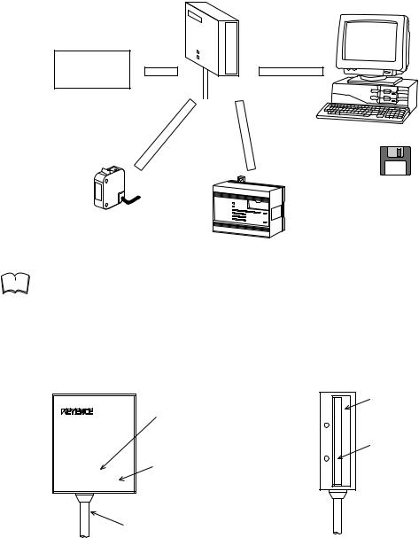
System Configuration
BL-180/185 |
RS-232C null modem cable |
IBM PC/AT |
|
OP-22149 (1.5 m) + OP-25057 |
|||
|
|||
|
(25to 9-pin adapter) |
or compatible |
|
|
|
||
|
RS-232C |
|
5VDC Power-supply unit*
Trigger input OK/NG
output BL-18H1E Setup software 3.5-inch version WINDOWS 3.1
Timing sensor
PLC etc.
Note |
The 5 VDC power supply unit must be purchased separately. |
|
|
|
|
The optional BL-U1 or BL-U2 power supply is also available.
Parts and Functions
BL-180

 OK/NG
OK/NG
BL-180 
 STABILITY
OK output: Lights in green. NG output: Lights in red.
STABILITY LED Indicates reading stability (see P. 31).
Light source/optical pickup
Light source LED Lights during reading
Cable (2 m)
vii
viii

Chapter 1
Connection and Installation
1.1 BL-180 Connections
1.1 BL-180 Connections
1.1.1 Wire colors and signal types
The following wires extend from the BL-180. Solder the required wires to a connector to connect the BL-180 to a computer/controller.
|
Wire Color |
|
|
Symbol |
|
|
Description |
|
|
|
Signal Direction |
||||||
|
|
|
|
|
|
|
|
|
|
|
|
|
|
|
|
|
|
|
Shield |
Shield |
|
|
|
|
|
|
|
Connect to ground (SG) |
|
|
|
—— |
|||
|
|
|
|
|
|
|
|
|
|
|
|
|
|
|
|
|
|
|
Purple |
RS- |
|
|
|
SD (TXD) |
Send data |
|
|
|
Output |
||||||
|
|
232C |
|
|
|
|
|
|
|
|
|
|
|
|
|
|
|
|
Brown |
|
|
|
RD (RXD) |
Receive data |
|
|
|
Input |
|||||||
|
|
|
|
|
|
|
|
|
|||||||||
|
|
|
|
|
|
|
|
|
|
|
|
|
|
|
|
|
|
|
Pink |
|
|
|
|
|
RS (RTS) |
Request to send (always on) |
|
|
|
Output |
|||||
|
|
|
|
|
|
|
|
|
|
|
|
|
|
|
|
|
|
|
Blue |
|
|
|
|
|
CS (CTS) |
Request to receive |
|
|
|
Input |
|||||
|
|
|
|
|
|
|
|
|
|
|
|
|
|
|
|
|
|
|
Black |
GND (SG) |
|
|
Ground (common ground for |
|
|
|
—— |
||||||||
|
|
|
respective signals) |
|
|
|
|||||||||||
|
|
|
|
|
|
|
|
|
|
|
|
|
|
|
|||
|
|
|
|
|
|
|
|
|
|
|
|
|
|
|
|
|
|
|
Yellow |
TIM |
|
|
|
|
|
|
|
Trigger input |
|
|
|
Input |
|||
|
|
|
|
|
|
|
|
|
|
|
|
|
|
|
|
|
|
|
White |
OK |
|
|
|
|
|
|
|
OK output |
|
|
|
Output |
|||
|
|
|
|
|
|
|
|
|
|
|
|
|
|
|
|
|
|
|
Gray |
NG |
|
|
|
|
|
|
|
NG output |
|
|
|
Output |
|||
|
|
|
|
|
|
|
|
|
|
|
|
|
|
|
|
|
|
|
Red |
+ 5V |
|
|
|
|
|
|
|
+ 5V power supply input |
|
|
|
Input |
|||
|
|
|
|
|
|
|
|
|
|
|
|
|
|
|
|
|
|
1.1.2 Power supply wiring |
|
|
|
|
|
|
|
|
|
|
|
|
|
|
|
|
|
|
|
|
BL-180 |
|
|
|
|
|
|
|
|
|
|||||
|
|
|
|
|
|
|
|
|
|
|
|
|
|
|
|
|
|
|
|
|
|
|
+5V |
|
Red |
|
|
|
|
|
|
|
|
||
|
|
|
|
|
|
+ |
|
|
|
|
5VDC |
||||||
|
|
|
|
|
|
|
|
|
|
|
|
|
|
|
|||
|
|
|
|
|
|
|
|
|
|
|
|
|
|
|
|
|
|
|
|
|
|
|
GND |
|
Black |
|
|
|
|
|
|
|
|
||
|
|
|
|
|
|
|
|
|
|
|
|
|
|||||
|
|
|
|
|
|
|
|
|
|
|
|
|
|
|
|
|
|
CAUTION |
• Be sure to match the polarities of the power supply when soldering the con- |
|
nections. Reversing the polarities will damage the unit. |
|
|
|
• Make sure that the power supply provides a stable 5 VDC ± 5%. If the power |
|
supply does not function in the above range, it can damage the unit. |
|
• Do not use a power cable longer that 2 meters. A long power cable can cause |
|
a voltage drop, preventing the BL-180 from starting properly. |
|
• If the power supply is UL rated, it must provide Class 2 output. |
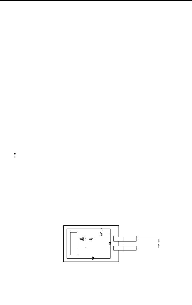
1.1.3 Wiring I/O
Trigger (TIM) input
The trigger input is used to signal the BL-180 to start reading (Start laser emission).
The trigger input is a non-voltage input (TTL input is also available).
Internal circuit
BL-180
4.7
10KΩ KΩ 


 TIM Yellow
GND Black
5VDC
With or without relay
2
1.1 BL-180 Connections
OK/NG output
This output signals whether the readout data is the same as the preset data. When no preset data has been registered, the signal indicates bar code read status. It is an NPN open-collector output.
Internal circuit
BL-180
1kΩ |
OK/NG Write/Gray |
Load |
|
|
|
|
|
|
GND |
Black |
+ |
|
|
|
|
|
|
*Rated load: 24 VDC |
|
|
|
(100 mA) max. |
|
1.1.4 RS-232C Connections
Note |
This BL-180 setup software applies to port 1 and port 2 only. |
|
|
|
|
Communication cannot be performed with another port.
When using a D-sub 9-pin connector:
|
BL-180 |
|
|
|
|
|
|
|
|
PC |
|
|
Shield |
Shield |
|
|
|
|
|
|
|
|
|
– |
Connector case |
|
|
|
|
|
|
|
|
|
||||
SD |
Purple |
|
|
|
|
|
|
|
|
|
2 |
RD |
|
|
|
|
|
|
|
|
|
||||
RD |
Blown |
|
|
|
|
|
|
|
|
|
3 |
SD |
|
|
|
|
|
|
|
|
|
||||
CS |
Blue |
|
|
|
|
|
|
|
|
|
7 |
RS |
|
|
|
|
|
|
|
|
|
||||
RS |
Pink |
|
|
|
|
|
|
|
|
|
8 |
CS |
|
|
|
|
|
|
|
|
|
||||
GND |
Black |
|
|
|
|
|
|
|
|
|
5 |
SG |
|
|
|
|
|
|
|
|
|
||||
+5V |
Red |
|
|
|
|
|
|
|
|
|
4 |
DR |
|
|
|
|
|
|
|
|
|
||||
|
|
|
|
|
|
|
|
|
|
|
6 |
ER |
|
|
|
|
|
|
|
|
|
|
|
||
|
+ |
|
|
|
|
|
|
D-sub 9-pin (male) |
||||
|
|
|
5VDC |
# 4-40 screw |
||||||||
|
|
|
|
|
|
|
||||||
Use a metallic connector housing for the D-sub 9-pin connector. Connect the shielded cable with the connector housing.
When using a D-sub 25-pin connector:
|
BL-180 |
|
|
|
|
|
|
|
|
PC |
|
|
Shield |
Shield |
|
|
|
|
|
|
|
|
|
1 |
FG |
|
|
|
|
|
|
|
|
|
||||
RD |
Blown |
|
|
|
|
|
|
|
|
|
2 |
SD |
|
|
|
|
|
|
|
|
|
||||
SD |
Purple |
|
|
|
|
|
|
|
|
|
3 |
RD |
|
|
|
|
|
|
|
|
|
||||
CS |
Blue |
|
|
|
|
|
|
|
|
|
4 |
RS |
|
|
|
|
|
|
|
|
|
||||
RS |
Pink |
|
|
|
|
|
|
|
|
|
5 |
CS |
|
|
|
|
|
|
|
|
|
||||
GND |
Black |
|
|
|
|
|
|
|
|
|
7 |
SG |
|
|
|
|
|
|
|
|
|
||||
+5V |
Red |
|
|
|
|
|
|
|
|
|
6 |
DR |
|
|
|
|
|
|
|
|
|
||||
|
|
|
|
|
|
|
|
|
|
|
20 |
ER |
|
|
|
|
|
|
|
|
|
|
|
||
|
+ |
|
|
|
|
|
|
D-sub 25-pin (male) |
||||
|
|
|
5VDC |
M 2..6 screw |
||||||||
|
|
|
|
|
|
|
||||||
Note |
Be sure the BL-180’s shielded cable is properly connected. Refer to “1.1.3 Con- |
|
|
|
necting shielded cables” in the User’s Manual. |
|
|
|
3
1.1 BL-180 Connections
Hints on correct use
Trigger (TIM) input
Set the trigger input to be long enough to allow the laser beam to cover the entire bar code.
If the trigger input needs to be on for only a short period of time, select one-shot mode.
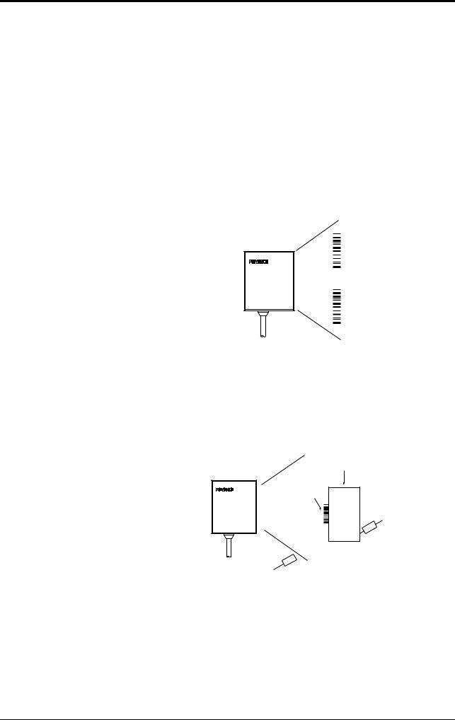
Influence from mirror surface
If a mirror surface (metallic surface) is near the bar code and the laser beam reflects off the mirror, the BL-180 may cause a read error. Protect the unit from the influence of a mirror surface by covering the surface or changing the bar code label position.
Bar code pitch
Do not place several bar codes in the field of the laser beam, unless you are in multi-label read mode (Multi 3).

 OK/NG
OK/NG
BL-180 
 STABILITY
If you use multi-label read mode (multi 3), the BL-180 can simultaneously read 2 to 4 bar codes in the field of the laser beam.
Influence from photoelectric sensor
When using a photoelectric sensor to control trigger, block the sensor beam so it does not enter the BL-180 optical pickup.
The beam from the photoelectric sensor can interfere with the BL-180, deteriorating reading performance. If this case, reposition the photoelectric sensor.
Object
Bar code

 OK/NG
OK/NG
BL-180 
 STABILITY
Light source
Optical pickup
4

1.1 BL-180 Connections
Bar code height
The bar code height must be at least 3 mm. However, adjust any bar code of 3 mm or more height so that it is arranged from one end to the other on the lightreceiving axis.
|
Light- |
|
3 mm or more |
receiving |
|
axis |
||
|
5

1.2 Installing the BL-180 Series
1.2 Installing the BL-180 Series
Installation method

 CAUTION
Use the mounting holes on the side panel to install the unit. To prevent dust from entering the unit, seals have been placed over the screw holes. Remove the seals before mounting.
Using the supplied mounting brackets
Install the BL-180 Series as shown in the figures below.
BL-180 pattern 1 |
BL-180 pattern 2 |
M3 screws
M3 screws
(BL-185)
M3 screws
•Select screws of the proper length by checking the thickness of the plate used for mounting. (The screws provided are for use with the mounting bracket.)
•For the mounting hole diameter, see page 65.
Installation with no mounting bracket
(BL-180) |
(BL-185) |
•Prepare M3 male screws separately.
•Although the mounting holes are on both sides of the unit, only one side should be mounted.
•For the mounting hole diameter, see page 65.
Do not insert screws into the BL-180 by 5 mm or deeper. Doing so may damage the unit parts.
Select screws of the proper length by checking the thickness of the plate used for mounting.
6

1.2 Installing the BL-180 Series
Mounting angle and mounting distance
BL-180
BL-180
BL-185
|
5 |
|
3 . |
||
. |
12 |
|
15 |
||
|
||
33
10°
Light-receiving axis
|
|
Set the angle and reading distance by referring to the read range characteristics |
|
|
and angle characteristics described on page 63 and 64. |
|
|
The allowable reading distance and angle may vary depending on the narrow bar |
|
|
width of the bar code, the bar code size, and the readability of the bar code. Set |
|
|
these parameters after performing a test read of the required bar code using the |
|
|
unit. |
Note |
Do not set the unit at an angle at which the light-receiving axis is perpendicular to |
|
|
|
the surface of the bar code. The beam will be fully reflected into the reader, mak- |
|
|
|
|
|
ing correct reading impossible (see page 64). |
|
|
Set the angle so that the light-receiving axis will be centered on the bar codes. |
|
|
Bar codes of insufficient height may deviate from the desired position in relation |
|
|
to the light-receiving axis. Be sure to position the unit carefully. (The bar codes |
|
|
must have a height of at least 3 mm.) |
|
|
The reading check test mode (see page 17) allows you to set the optimal reading |
|
|
position. |
7

1.2 Installing the BL-180 Series
8

Chapter 2
Functions for Reading Operation

2.1 Read Operation
2.1 Read Operation
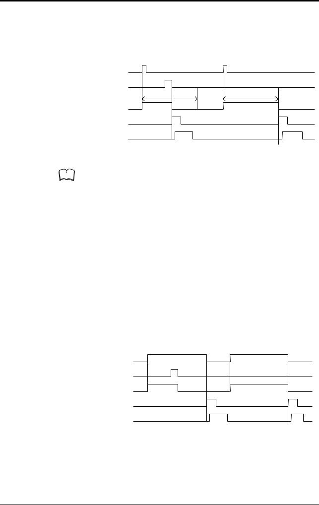
2.1.1 Scanning method
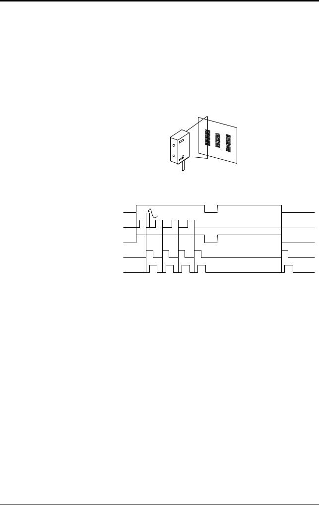
There are two methods for triggering the BL-180 to read bar codes; the “Level signal” method and the “One-shot signal” method. The example given for these two methods uses the “single label read mode” (see page 12), which reads one bar code while trigger input turns on once, and uses the “after read” as the data-send mode (see page 11).
Level signal trigger
When the trigger input turns on, LED emission begins and the the unit begins reading. The LED turns off after reaching the specified decode count. Then, the unit sends the readout data.
|
|
<Succeed to read> |
|
<Fail to read> |
|||||||||
Trigger input |
|
|
|
|
|
|
|
*1 |
|
|
|
|
|
Bar code |
|
|
|
|
|
|
|
|
|
|
|
|
|
|
|
|
|
|
|
|
|
|
|
|
|
||
|
|
|
|
|
|
|
|
|
|
|
|||
LED beams |
|
|
*2 |
|
|
|
|
|
|
|
|
||
Communication time |
|
|
*3 |
|
|
|
|
|
|
|
|||
|
|
|
|
|
|
|
|
|
|
||||
|
|
|
|
|
|
|
|
|
|
|
|
|
|
OK/NG output |
|
|
|
OK/NG |
*4 |
|
|
|
NG |
|
|||
|
|
*5 |
|
|
|
|
|
|
|
|
|
|
|
1.Set trigger input so that it stays on long enough for the LED beam to cover the entire bar code.
2.After the trigger input exceeds the preset input time, the LED begins to emit.
3.The communication time can be obtained from the following expression:
Data bits + (1: If parity is used) + Start/stop bit |
X (code length of data to be sent + Header/ |
|
Baud rate |
||
number of characters in delimeter) |
||
|
4.The length of time that the OK/NG output is on can be changed to between 10 ms and 2.55 s.
5.The OK/NG output turns on 5 ms after the data has been read (or trigger input turns off in case of reading failure).
10
2.1 Read Operation
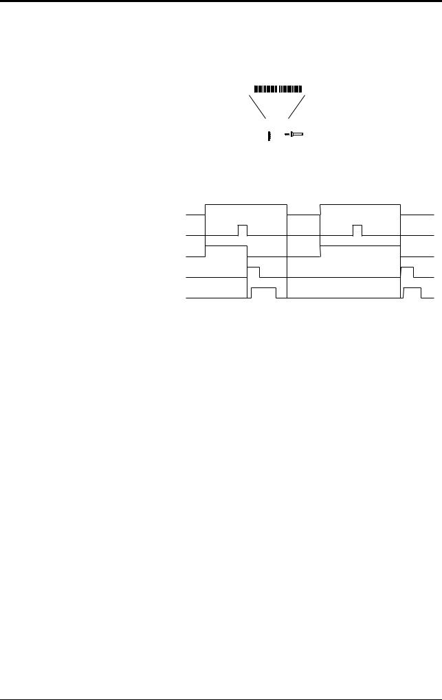
One-shot signal trigger
The unit detects the rising edge of the trigger input and starts reading bar codes for the preset input time. The LED beam turns off after reaching the specified decode count and the unit sends the readout data.
The remaining actions are the same as those for level signal trigger.
|
<Succeed to read> |
<Fail to read> |
Trigger input |
*1 |
|
Bar code |
Preset input time |
Preset input time |
|
||
LED beams |
|
|
Communication time |
|
|
OK/NG output |
OK/NG |
NG |
|
|
1. After the trigger input exceeds the preset input times, the LED begins to emit.
Note |
• The BL-180 can read up to 4 types of bar codes without changing the bar code |
|
|
|
type setting (see page 32). |
|
|
|
•For general operation, see "Level signal trigger"
•Choose “One-shot signal trigger” when the trigger input signal is very short or you want to set the input time.
2.1.2Data-send mode
In the single label read mode only, you can select from the two data send modes (OK/NG output on trigger) described below: In the multi-label read mode, you can only select the “send after reading” mode.
Send after read
The unit outputs the communication and OK/NG signals after a sucessful read (trigger output turns on as many times as the preset decode count). This is the same operation as in the time chart described in “1.1 Scanning method”. Normally, this is the method you should use.
Send at trigger input
The unit outputs the communication and OK/NG signal when the trigger input turns off (or the preset input time has passed if one-shot signal trigger is selected).
<Succeed to read> |
<Fail to read> |
Trigger input
Bar code
LED beams
Communication time
OK/NG |
NG |
OK/NG output
11
2.2 Read modes
2.2 Read modes
The BL-180 provides 4 types of read modes.
2.2.1 Single label read mode
This mode allows the unit to read one bar code during one trigger input signal.
The operation and timing chart are described on page 10.
2.2.2 Multi-label read mode 1 (Multi 1)
This mode allows the unit to read several bar codes printed on one label as shown below during one trigger input signal. The unit outputs the readout data sequentially.
Multi-label read mode 1 operation
<Succeed to read> |
<Fail to read> |
Trigger input
Repeat reading time
Bar code
LED beams
Communication time
OK/NG output |
OK |
OK |
OK |
OK |
NG |
In the multi-label read mode 1, the unit reads several bar codes continuously, and outputs them sequentially as it reads while LED beam remains on and trigger input turns on after bar codes have been read (or during the preset input time if oneshot signal trigger is selected).
To prevent the unit from reading the same bar code twice, the time for one bar code to pass across the LED beam’s field and read, plus the repeat reading time must be set (100 ms to 25.5 s). During the repeat reading time, the unit cannot read the same bar code repeatedly, but can read different bar codes.
A reading error is issued only when the unit cannot read any bar code while the trigger input is on.
For OK/NG output, “OK” turns on every time the unit reads a bar code and “NG” turns on if the unit fails to read a bar code. (Comparison to the preset data is not performed.)
12
2.2 Read modes
2.2.3 Multi-label read mode 2 (Multi 2)
As with multi 1 mode, this mode allows the unit to read several bar codes continuously while the trigger input is on. (The number of bar codes that can be read depends on the buffer capacity. See page 48.) The difference between the two modes is that multi 2 modesends all the readout data at one time after the trigger input turns off.
Multi-label read mode 2 operation
|
<Succeed to read> |
<Fail to read> |
Trigger input |
Repeat reading |
|
|
|
|
|
time |
|
Bar code
1 2 3 4 5
LED beams
Communication time
|
1 2 3 4 5 |
|
OK/NG output |
OK |
NG |
|
|
Multi 2 mode allows the unit to read several bar codes while the trigger input is on (or during the preset input time if one-shot signal trigger is selected) and sends all the readout data at one time after the trigger input turns off (or after the preset input time is expired if one-shot signal trigger is selected).
To prevent the unit from reading the same bar code twice, the time for one bar code to pass across the LED light’s field and read, plus the repeat reading time must be set. During the repeat reading time, the unit cannot read the same bar code repeatedly, but can read different bar codes.
For OK/NG output, after trigger input turns off, “OK” turns on if the unit reads at least one bar code and “NG” turns on if the unit fails to read a bar code. (Comparison to the preset data is not performed.)
Reading data format
Header |
1st |
, |
2nd |
, |
3rd |
, |
4th |
, |
Delimeter |
|
data |
data |
data |
data |
|||||||
|
|
|
|
|
|
|||||
|
|
|
|
|
|
|
|
|
|
Each data packet is separated by a comma (, : 2CH) (intermediate delimiter).
The unit sends as many data packets the number of bar codes read.
See page 46 for “header string” and “delimeter”.
2.2.4 Multi-label read mode 3 (Multi 3)
As described in multi-label read modes 1 and 2, this mode also allows the unit to read several bar codes (up to 4 codes) while the trigger input is on.
The unit sends the readout data at one time according to a specified sequence after the trigger input turns off. When up to 4 codes are in the LED beam’s field, the unit can simultaneously reads all of them.
13

2.2 Read modes
Operation of multi-label read mode 3
This mode allows the unit to continuously read each one of 4 bar code types “Code 1”, “Code 2”, “Code 3”, and “Code 4” as specified in the “code setup” of the setup software (see page 32). If 3 types are specified in the “code setup”, the unit reads 3 bar codes (each of 3 types). If 2 types are specified, the unit reads 2 bar codes.
The following time chart is given.
Trigger input
Bar Code
Code 1 Code 2 Code 3 Code 4
LED beams
Communication time
Code 1 |
Code 2 |
Code 3 |
Code 4 |
OK/NG output |
OK |
|
NG |
|
|
|
The above example chart is with all four codes specified in the “code setup” of the setup software.
•The bar code reading sequence is not fixed.
•The unit communicates the readout data in the order of Code 1 to Code 4. After the trigger input turns off, the unit sends all the data at one time.
•For OK/NG output, “OK” turns on if the unit reads all the specified Codes 1 to 4 and “NG” turns on if the unit fails to read at least one bar code. (Comparison to the preset data is not performed.)
Reading data format
Header |
Data read |
|
Data read |
|
Data read |
|
Data read |
|
|
from Code |
, |
from Code |
, |
from Code |
, |
from Code |
, |
Delimeter |
|
|
1 |
|
2 |
|
3 |
|
4 |
|
|
|
|
|
|
|
|
|
|
|
|
•Each data packet is separated by a comma (, : 2CH) (intermediate delimiter).
•If an read error occurs on any one of Codes 1 to 4, or the corresponding bar code does not exist, “ERROR” (see page 49 for the reading error codes), instead of the read data is sent.
•See page 48 for “header string” and “delimeter”.
Example Suppose that the following codes are specified:
Code 1 --- |
CODE39, 10 digits |
Code 2 --- |
EAN/UPC, 13 digits |
Code 3 --- |
None |
Code 4 --- |
CODE39, 8 digits |
When the unit successfully reads all 3 types of codes:
Header |
ABCDE12345 |
, |
4901234567894 |
, |
KEYENCE |
Delimeter |
When the unit fails to read Code 1 (CODE39, 10 digits)
Header |
ERROR |
, |
4901234567894 |
, |
KEYENCE |
Delimeter |
When the unit fails to read Code 1 (CODE39, 10 digits) and Code 4 (CODE39, 8 digits)
Header |
ERROR |
, |
4901234567894 |
, |
ERROR |
Delimeter |
When the same type of data having the same digits is specified to all Codes 1 to 4, the unit sends the data in the reading order.
14

2.2 Read modes
Example
Suppose that the following codes are specified:
Code 1 --- CODE39, 7 digits
Code 2 --- CODE39, 7 digits
Code 3 --- CODE39, 7 digits
Code 4 --- CODE39, 7 digits
Header |
ABCD123 |
, |
XYZ3333 |
, |
1234567 |
, |
KEYENCE |
, |
Delimeter |
Note |
The unit cannot read the bar code having the same content twice while trigger in- |
|
|
|
put turns on once. |
|
|
|
15
2.3 Label orientation mode
2.3 Label orientation mode
As shown below, this mode allows the unit to read bar codes only in the specified orientation when bar code labels are moving both in the forward and reverse orientations.
Forward orientation Reverse orientation
9000000 |
4 |
4 9 0 0 0 0 0 0
OK/NG |
STABILITY |
|
BL-180 |
Normally, the unit can read bar codes regardless of the orientation.
<Specified orientation> |
<Non-specified orientation> |
Trigger input
Bar code
LED beams
Communication time
OK/NG output |
OK/NG |
NG |
|
|
An reading error is issued when the unit reads a bar code label running in the orientation which is not specified.
The above chart applies to the single label read mode. You can also use this mode together with the desired multi-label read mode. However, in any case, the unit reads bar codes running in the specified orientation only.
You can specify the orientation individually for Codes 1 to 4, such as specifying “forward orientation” for Code 1, and “reverse orientation” for Code 2.
16

2.4 Test Mode
2.4 Test Mode
Test mode can be used for the bar code reading test. Because trigger input is not required, this mode allows you to perform a reading test easily. You can select one of the following 3 methods to enter the test mode.
Send the command
Enter test mode by sending the serial command for the test mode (TEST1,
TEST2). Commands should be entered in all uppercase characters.
Turning on trigger input
You can use the BL-180 to switch to test mode by turning on the trigger input (see page 35). If you select this method to enter the test mode, trigger input is disabled to ensure normal operation.
Turning on power supply
You can set the BL-180 to enter test mode by turning on the power supply (see page 37).
Note When you try to enter the test mode by turning on trigger input, you cannot use the serial command to enter the test mode.
The following 2 types of test modes are available:
Reading rate check mode
The unit scans a bar code100 times and analyzes how many times it can decode the scanned data (reading rate). This mode is useful in the following cases:
•When adjusting the mounting distance and angle
•When verifying the reading stability of the bar code to be used
•The analyzed result will be output anytime (every 100 scans) using the following format:
Delimiter
Readout data |
: |
m |
% |
m = 0 to 100 (zero-suppressed)
• Although an OK/NG signal is not output, the OK/NG LED lights (see page 19).
Tact check mode
In this test mode, the unit counts how many scans can be decoded (the decode count) while reading one bar code.
This mode is useful when testing which line speed can be expected when actually implementing the BL-180 system on the line.
•The analyzed data is output using the following format 0.2 seconds after the bar code has passed the LED beam’s field.
Delimiter
Readout data |
: |
m |
m = 1 to 999 (zero-suppressed)
•The unit continues to read a bar code while the code is in the LED beam’s field and does not output the result. If the LED beam does not detect a bar code for 0.2 seconds, the unit stops scanning and outputs the result.
•If the unit reads the same bar code twice within the 0.2 seconds, the unit cannot separate the bar codes and will add to the read count. However, the unit can continuously reads different bar codes within the 0.2 seconds by recognizing the delimiter.
17

2.4 Test Mode
•The read count can be up to 9999.
•Although an OK/NG signal is not output, the OK/NG LED lights (see page 19).
Note When the unit is running in test mode, the LED beam remains on, which can shorten the LED’s service life.
Select the test mode only when you need to perform a test read.
Avoid long emission times.
When using the “additional information” (see page 21 to 22) in the test mode, the selected data is added in the same manner as in the normal operation mode. However, only when selecting the reading rate check mode, the decode count and scan count are not added to the analyzed results.
18

2.5 STABILITY LEDs
2.5 STABILITY LEDs
STABILITY LEDs allows you to easily check reading stability.
STABILITY LEDs light only when the test mode gets started or the decode count adding function (see P. 34) is used.
Indication of reading stability
When reading rate check mode is selected
STABILITY LEDs light according to the reading rate shown in the table below. Although, in the test mode, the unit does not output an OK/NG singnal, the OK/NG LED lights as below. (Comparison to the preset data is not performed.)
Reading rate |
STABILITY LED |
OK/NG LED |
|
|
|
80 to 100% |
Green |
Green |
|
|
|
50 to 79% |
Orange |
Green |
|
|
|
20 to 49% |
Red |
Green |
|
|
|
1 to 19% |
—— |
Green |
|
|
|
0% |
—— |
Red |
|
|
|
When tact check mode is selected
STABILITY LEDs light according to the scan count (decode count), which indicates the number of successful reads, as shown in the table below.
Although, in the test mode, the unit does not output an OK/NG signal, OK/NG LED lights as below. (Comparison to the preset data is not performed.)
Decode count |
STABILITY LED |
OK/NG LED |
|
|
|
|
|
50 or more |
Green |
Green (decode counts are |
|
|
|
equal to or greater than |
|
10 to 49 |
Orange |
||
the preset match count) |
|||
|
|
||
5 to 9 |
Red |
||
Red (decode counts are |
|||
|
|
||
1 to 4 |
—— |
less than the preset |
|
match count) |
|||
|
|
||
|
|
|
|
0 |
—— |
Red |
|
|
|
|
When using the decode count adding function
STABILITY LEDs light as shown in the table below according to the decode count.
OK/NG output (OK/NG LED) turns ON/OFF based on the result of comparison to the preset data.
Decode count |
STABILITY LED |
|
|
50 or more |
Green |
|
|
10 to 49 |
Orange |
|
|
5 to 9 |
Red |
|
|
4 or less |
—— |
|
|
CAUTION |
When you do not use the decode count adding function or use the multi-label read |
|
mode 3, STABILITY LEDs do not light. |
|
19
2.6 Preset Function (Compare with:)
2.6 Preset Function (Compare with:)
2.6.1 What is the preset function?
The BL-180 can store one bar codeas preset data. It compares the preset data to the bar code data actually read and outputs an OK/NG signal to whether there is a match.
Using the BL-180 preset function, you can prevent the wrong products from entering the line without using a PC.
If no preset data is registered, the unit outputs OK when it successfully reads a bar code and NG when it fails to read a bar code.
•See page 10 to 16 for output timing.
•Use the setup software and serial command to register the preset data (see page 39 and page 59).
Note |
• The bar code actually read can be compared to the preset data only in the sin- |
|
|
|
gle label read mode. |
|
|
|
•See page 70 if you want to use CODE128.
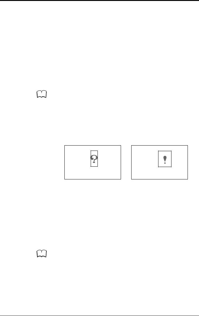
2.6.2Wildcard symbols (“!” and “?”)
Using “!” and “?” in the preset data allows for flexible settings.
?: Does not define numeric values (characters) of certain digit(s) of the bar code.
!: Ignores numeric values and symbols within the dot box and recognizes the bar codes as the same group.
4912 3 4 5 6
4912 5 2 5 6
4912 AB5 6
4912 3 4 5 6
4912 C
4912
When using “?” data as “4912??56”, 2 digits positioned in “??” can contain any numeric values (or characters), expanding the allowable range. Identifies all the bar codes to be OK as long as the beginning or ending strings match.
When using “!” as “4912!”, any bar code which begins with “4912” will be OK. When using “!” as “!4912”, any bar code which ends with “4912” will be OK.
Setting examples |
1. “ABC?” |
ABCD (OK), |
ABC3 (OK), |
ABC (NG), |
ABCDE (NG) |
|
||
|
|
2. |
“ABC!” |
ABCD (OK), |
ABC3 (OK), |
ABC (OK), |
ABCDE (OK), |
AB (NB) |
|
|
3. |
“?????” |
Any 5-digit bar code will be OK. |
|
|
|
|
|
|
4. |
“!CDE” |
ABCDE (OK), |
3CDE (OK), |
CDE (OK), |
ABBDE (NG), |
ADE (NG) |
|
|
5. |
“A!E” |
ABCDE (OK), |
A3CE (OK), |
ABCD (NG), |
AE (OK) |
|
Note |
You can use “!” only once in the setting. |
|
|
|
||||
|
|
|
|
|
|
|
|
|
If you do not register preset data, “!” is automatically registered. Therefore, when the unit sucessfully reads a bar code, “OK” is output; when the unit fails to read, “NG” is output.
You cannot use the “*” character as a wild card symbol with the BL series.
20

2.7 Additional Information
2.7 Additional Information
When sending the bar code data, you can add the following data to the readout data.
Additional information types
Decode match count add function
Adds the number of successful scans during one bar code reading (decode count) to the end of the readout data (up to 9999 count). However, this decode count is never less than the preset decoding match count.
• This function can be used to check reading stability and code label quality.
|
|
|
|
|
|
Delimiter |
||
|
|
|
|
Readout data |
|
: |
d |
|
|
|
|
|
|
|
|
d = [Decoding match count] to |
|
|
|
|
|
|
|
|
9999: Decode count |
|
|
|
|
|
The value is zero-suppressed. |
||||
|
|
When using this function, output turns on at a different time from normal opera- |
||||||
|
|
tion. |
|
|
|
|||
|
|
• |
In single label read mode, output turns on after one bar code has been read |
|||||
|
|
|
(after trigger input turns off). Even if you set the data-send to “after read”, the |
|||||
|
|
|
data is forced sent after trigger input turns off. |
|
|
|||
|
|
• |
In multi-label read mode 1, a bar code passes across the LED beam’s field, |
|||||
|
|
|
after repeat read time, and is finally output. |
|
|
|
||
|
|
• |
In multi-label read mode 2 or 3, operation is the same as when you do not use |
|||||
|
|
|
the decode match count adding function. |
|
|
|
||
Note |
When you use the decode count adding function, STABILITY LEDs light to show |
|||||||
|
|
reading stability (see P. 31). |
|
|
|
|||
|
|
|
|
|
||||
Scan count add function (valid only when using the read count add function)
Adds the number of scans, including when no bar code exists, to the end of the decode count (up to 9999).
Delimiters
Readout data |
: |
d |
/ |
s |
m = 1 to 999 (zero-suppressed)
The value is zero-suppressed.
Code type add function
Adds the bar code type before the readout data .
Delimiter
t |
: |
Readout data |
t = 0 |
|
:Code39 |
1 |
|
:ITF |
2 |
|
:Industrial 2 of 5 |
3 |
|
:Codabar |
4 |
|
:EAN/UPC (A•E) |
5 |
|
:CODE 128 |
6 |
|
:COOP 2 of 5 |
7 |
|
:Read error |
21

2.7 Additional Information
label orientation add function
Adds the orientation of bar code travel before the readout data.
Delimiter
r |
|
: |
Readout data |
r = F |
|
:Forward |
|
R |
|
:Reverse |
|
If an read error occurs, this information is not added.
Forward orientation Reverse orientation
9000000 |
4 |
4 9 0 0 0 0 0 0
OK/NG |
STABILITY |
|
BL-180 |
|
|
Order of additional information
If you select to include all the additional information functions, they appear in the following order:
|
|
Code type |
: |
label |
: |
Readout data |
: |
Decode match |
: |
Scan count |
|
|
orientation |
count |
|||||||
|
|
|
|
|
|
|
|
|
||
Note |
|
|
|
|
|
|
|
|
|
|
You can change the delimiter as desired (one character), except the delimiter of |
||||||||||
|
|
the scan count. |
|
|
|
|
|
|
|
|
|
|
|
|
|
|
|
|
|
||
22
Loading...