


96M1127
User’s Manual
Laser Bar Code Reader
BL-600 Series

Safety Precautions
This instruction manual describes the operation and function of the BL-600. Read this manual carefully to ensure safe use and maximum performance from your BL600. The BL-600 Series uses a semiconductor laser as light source. Before using the product, see "Laser Safety Precautions" on page 1 to learn the safe and correct method of using the BL-600 Series.
Symbols
The following symbols alert you to important messages. Be sure to read these messages carefully.
|
WARNING |
Failure to follow instruction may lead to injury. (electric |
|
shock, burn, etc.) |
|
|
|
Failure to follow instructions may lead to product damage. |
|
CAUTION |
|
|
|
|
|
|
|
Note: |
Provides additional information on proper operation. |
|
|
Provides reference information about the operation. |
|
Reference: |
||
|
|
|
General Precautions
•At startup and during operation, be sure to monitor the functions and performance of the BL-600.
•We recommend that you take substantial safety measures to avoid any damage in the event a problem occurs.
•Do not open or modify the BL-600 or use it in any way other than described in the specifications.
•When the BL-600 is used in combination with other instruments, functions and performance may be degraded, depending on operating conditions and the surrounding environment.
•Do not use the BL-600 for the purpose of protecting the human body.
i
Warnings and Cautions Specific to the BL-600
CAUTION |
• The BL-600 uses a 5 V DC power supply. Using a different voltage level may |
|||||||||
damage the unit. |
||||||||||
|
||||||||||
|
When using the KEYENCE power supply unit BL-U1, BL-U2, N-42 or N-48, |
|||||||||
|
select the voltage level which can be supplied by the power supply unit. If a |
|||||||||
|
nonconforming power supply is connected, the BL-600 may be damaged. |
|||||||||
|
• Before connecting or disconnecting the cable, be sure to turn off any device |
|||||||||
|
connected to the BL-600 Series. Otherwise, the BL-600 Series may be dam- |
|||||||||
|
aged. |
|||||||||
|
• Do not disassemble or modify the BL-600 Series, as this may cause product |
|||||||||
|
failure. |
|||||||||
|
• Locate cables as far as possible from high-voltage lines and power lines. |
|||||||||
|
Otherwise, generated noise may cause product failure or malfunctions. |
|||||||||
|
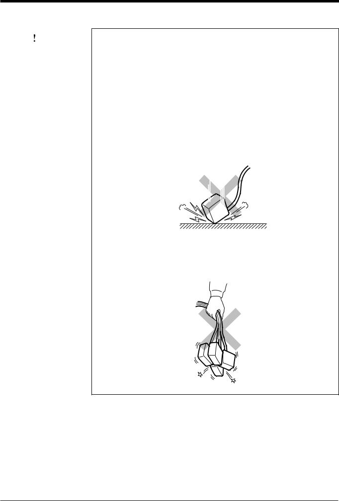
• The BL-600 is a precision instrument. If the unit is dropped or shocked, it may |
|||||||||
|
be damaged. Take due consideration when transporting or installing the unit. |
|||||||||
|
|
|
|
|
|
|
|
|
||
|
Incorrect |
|
|
|
|
|
|
|
|
|
|
|
|
|
|
|
|
|
|
|
|
|
|
|
|
|
|
|
|
|
|
|
|
|
|
|
|
|
|
|
|
|
|
|
|
|
|
|
|
|
|
|
|
|
|
|
|
|
|
|
|
|
|
|
|
|
|
|
|
|
|
|
|
|
|
|
|
|
|
|
|
|
|
|
|
|
|
•Do not hold the cables when carrying the units. The units may hit each other and become damaged.
Incorrect
96M1127 |
ii |

Environments and conditions for use
CAUTION |
|
To use the BL-600 Series properly and safely, do not install it in locations with the |
|
following conditions. Use of the BL-600 Series in improper environments may |
|
|
|
|
|
|
cause fire, electric shock, product failure, damage, or malfunction. |
|
|
• Locations where the BL-600 Series is exposed to direct sunlight |
|
|
• Locations where the ambient temperature drops below 0°C or exceeds 45°C |
|
|
• Locations where the relative humidity drops below 35% or exceeds 85% |
|
|
• Locations where condensation occurs due to a sudden change in temperature |
|
|
• Locations where a corrosive or flammable gas exists |
|
|
• Locations exposed to dust, salt, metal particles, or greasy fumes |
|
|
• Locations where the ambient light exceeds the range defined in the specifica- |
|
|
tions |
|
|
• Locations where the BL-600 Series is directly subjected to vibration or impact |
|
|
• Locations where water, oil, or chemicals may splash the BL-600 Series |
|
|
• Locations where a strong magnetic or electric field is generated |
|
|
|
If abnormal conditions are encountered
CAUTION |
|
If the following conditions are encountered, turn off the special power supply unit |
||
|
|
immediately. Continuing to use the BL-600 Series under abnormal conditions may |
||
|
|
|||
|
|
cause fire, electric shock, or product failure. |
||
|
|
Contact your nearest KEYENCE sales office or distributor (listed at the end of this |
||
|
|
manual) for repairs. |
||
|
|
• Water or foreign matter enters the BL-600 Series |
||
|
|
• |
The BL-600 |
Series is dropped or the housing is damaged. |
|
|
• |
The BL-600 |
Series produces smoke or an abnormal smell |
|
|
|
|
|
Note 1: You cannot perform any operation for 5 seconds after turning ON the BL600. During this time, the motor rotation stabilizes. Wait for a while after turning ON the BL-600, then start reading or another operation.
Note 2: The BL-600 Series has a housing rated as IP-65 (except for the special power supply unit). It is not affected if water splashes it; however, a proper reading may not be ensured if the transmitter/receiver is dirty (fingerprints, water, oil, or dust). In such cases, wipe the dirt off with a soft cloth moistened with alcohol.
iii
How this manual is organized
|
Chapter 1 |
|
Laser Safety Precautions |
|
|
|
|
||
|
|
|
|
|
|
Chapter 2 |
|
Overview |
|
|
|
|
|
|
|
|
|
This chapter describes the package contents, basic system configuration, and |
|
|
|
|
operation flow. |
|
|
|
|
|
|
|
Chapter 3 |
|
Connection and Wiring |
|
|
|
|
|
|
|
|
|
This chapter describes the connections and wiring between the BL-600 Series, |
|
|
|
|
special power supply unit, and peripheral devices. |
|
|
|
|
|
|
|
Chapter 4 |
|
Setup Software |
|
|
|
|
This chapter describes the usage of the setup software to set or perform reading |
|
|
|
|
tests of the BL-600. |
|
1
2
3
4
Chapter 5 |
|
Installation |
This chapter describes the procedure and cautions for the installation of the BL-600 Series and special power supply unit.
Chapter 6 Reading Operation and Other Functions
This chapter describes the reading operation and other functions, such as test mode, of the BL-600 Series.
Chapter 7 Serial Communication
This chapter describes the serial communication control.
Chapter 8 |
|
PLC Link |
This chapter describes the PLC link control.
Appendices
The appendix includes specifications, reading characteristics, dimensions, troubleshooting, and index.
Warranties
5
6
7
8
Appendices
Warranties
iv

Contents
Chapter 1 |
Laser Safety Precautions |
|
|
|
|
|
|
|
1.1 |
..........................................................................................Classification |
2 |
|
1.2 |
Warning Labels ...................................................................................... |
2 |
|
1.3 |
Labels Location ...................................................................................... |
3 |
|
1.4 |
Safety Consideration ............................................................................. |
4 |
|
1.5 |
Safety Features Provided with the BL-600 Series .............................. |
4 |
Chapter 2 |
Overview |
|
|
|
2.1 |
Package Contents List and the BL Series Lineup .............................. |
6 |
|
2.2 |
Part names and functions ..................................................................... |
8 |
|
2.3 |
System Configuration and Connection/Operation Procedures ....... |
12 |
|
2.3.1 |
Basic system configuration and connection/ |
|
|
|
operation procedures for RS-232C communication ............................... |
12 |
|
2.3.2 |
Basic system configuration and connection/ |
|
|
|
operation procedures for RS-422A communication ............................... |
13 |
|
2.3.3 |
Multi-drop link communication (RS-485) ................................................ |
14 |
Chapter 3 |
Connection and Installation |
|
|
|
|
|
|
|
3.1 |
............................................................Connecting BL-U1 and Wiring |
16 |
|
3.1.1 |
Connecting the BL-U1, AC power supply, and BL-600 Series ............... |
16 |
|
3.1.2 |
DIP switch setting .................................................................................. |
17 |
|
3.1.3 |
Terminals of I/O terminal block and wiring ............................................. |
18 |
|
3.1.4 |
Connecting RS-232C ............................................................................. |
20 |
|
3.1.5 |
Wiring the RS-422A ............................................................................... |
23 |
|
3.2 |
Connecting the BL-U2/N-42 and Wiring ............................................. |
25 |
|
3.2.1 |
Connecting the BL-U2/N-42, AC power supply, and BL-600 Series ...... |
25 |
|
3.2.2 |
Terminals of I/O terminal block and connections ................................... |
26 |
|
3.2.3 |
Connecting RS-232C (BL-U2) ............................................................... |
28 |
|
3.2.4 |
Connecting the N-42 to RS-422A .......................................................... |
31 |
|
3.3 |
Wiring without the Special Power Supply Units ............................... |
33 |
|
3.3.1 |
Pin assignments of the BL-600 Series connector |
|
|
|
and the connecting power supply .......................................................... |
33 |
|
3.3.2 |
I/O Wiring ............................................................................................... |
34 |
|
3.3.3 |
RS-232C connection .............................................................................. |
35 |
Chapter 4 |
Setup Software |
|
|
|
4.1 |
....................................Installing and Operating the Setup Software |
38 |
|
4.1.1 |
Installation and operation procedures .................................................... |
38 |
|
4.1.2 |
Installing setup software ........................................................................ |
39 |
|
4.1.3 |
Installation/Start-up ................................................................................ |
39 |
|
|
|
|
v

|
|
4.1.4 |
Initial screen ........................................................................................... |
40 |
|
|
4.1.5 |
Basic operation ...................................................................................... |
41 |
|
|
4.2 |
Setup Procedure .................................................................................. |
42 |
|
|
4.2.1 |
Model selection ...................................................................................... |
42 |
|
|
4.2.2 |
[[Main]] (Operation setting) screen ......................................................... |
42 |
|
|
4.2.3 |
[[Comm Settings-1]] (Communication parameters 1) screen ................. |
45 |
|
|
4.2.4 |
[[Comm Settings-2]] (Communication parameters 2) screen ................. |
46 |
|
|
4.2.5 |
[[Code setup]] (Bar code setting) screen ............................................... |
49 |
|
|
4.2.6 |
[[Utility]] screen ...................................................................................... |
53 |
|
|
4.3 |
Sending/Receiving Settings ................................................................ |
54 |
|
|
4.3.1 |
Sending/receiving settings to/from the BL-600 Series ........................... |
54 |
|
|
4.3.2 |
Sending/receiving settings to/from the BL-600 Series via the N-400 ..... |
57 |
|
|
4.4 |
Reading/Saving/Printing File .............................................................. |
59 |
|
|
4.4.1 |
[[Files]] screen ........................................................................................ |
59 |
|
|
4.4.2 |
Reading a previously saved setting file .................................................. |
59 |
|
|
4.4.3 |
Saving updated settings in a file ............................................................ |
60 |
|
|
4.4.4 |
Comparing the contents of the file currently |
|
|
|
|
being edited with a saved file ................................................................. |
61 |
|
|
4.4.5 |
Printing contents of a setting file ............................................................ |
61 |
|
|
4.4.6 |
Resetting the edited settings to the initial (factory) settings ................... |
62 |
|
|
4.5 |
Using Monitor ....................................................................................... |
62 |
|
|
4.5.1 |
Receiving data and checking the result ................................................. |
62 |
|
|
4.5.2 |
Command transmission ......................................................................... |
63 |
|
|
4.5.3 |
Starting the test mode ............................................................................ |
65 |
|
|
3.5.4 |
Changing the scanning width ................................................................. |
66 |
|
|
4.6 |
List of Error Messages ........................................................................ |
67 |
|
|
4.7 |
Example of printing from the setup software .................................... |
68 |
|
|
|
|
|
|
Chapter 5 |
Installation |
|
|
|
|
|
|
|
|
|
5.1 |
Installation of the BL-600 Series ........................................................ |
72 |
|
|
5.1.1 |
Situations to check for before installing the BL-600 Series .................... |
72 |
|
|
5.1.2 |
Mounting angle and distance ................................................................. |
74 |
|
|
5.1.3 |
Mounting the BL-600/601/600HA/601HA ............................................... |
75 |
|
|
5.1.4 |
Mounting the BL-650HA/651HA ............................................................. |
77 |
|
|
5.1.5 |
Mounting the BL-600 Series without the mounting bracket ................... |
79 |
|
|
5.2 |
Installation of the Special Power Supply Unit ................................... |
81 |
|
|
5.2.1 |
In-panel installation ................................................................................ |
81 |
|
|
5.2.2 |
Installing the BL-U1 ................................................................................ |
81 |
|
|
5.2.2 |
Installing the BL-U2 and N-42 ................................................................ |
83 |
|
|
|
|
|
|
Chapter 6 |
Functions for Reading Operation |
|
|
|
|
6.1 |
Read Operation .................................................................................... |
86 |
|
|
6.1.1 |
Scanning method ................................................................................... |
86 |
|
|
6.2 |
Read Modes .......................................................................................... |
88 |
|
|
6.2.1 |
Single label read mode .......................................................................... |
88 |
vi

|
6.2.2 |
Multi-label read mode 1 (Multi 1) ........................................................... |
89 |
|
6.2.3 |
Multi-label read mode 2 (Multi 2) ........................................................... |
90 |
|
6.2.4 |
Multi-label read mode 3 (Multi 3) ........................................................... |
91 |
|
6.3 |
Label Orientation Mode ....................................................................... |
93 |
|
6.4 |
Test Mode ............................................................................................. |
94 |
|
6.4.1 |
Reading rate check mode ...................................................................... |
94 |
|
6.4.2 |
Tact check mode .................................................................................... |
97 |
|
6.4.3 |
Online test mode .................................................................................... |
99 |
|
6.5 |
Preset Function (Compare with:) ..................................................... |
101 |
|
6.5.1 |
Preset function ..................................................................................... |
101 |
|
6.5.2 |
Using “?” and “!” in the preset data ...................................................... |
101 |
|
6.6 |
Additional information function ....................................................... |
102 |
|
6.6.1 |
Decode match count add function ....................................................... |
102 |
|
6.6.2 |
Scan count add function |
|
|
|
(valid only if using the decoding count add function) ........................... |
102 |
|
6.6.3 |
Code type add function ........................................................................ |
103 |
|
6.6.4 |
Label orientation add function .............................................................. |
103 |
|
6.6.5 |
Symbology ID add function .................................................................. |
104 |
|
6.6.6 |
PMI add function .................................................................................. |
104 |
|
6.6.7 |
Order of the additional information ....................................................... |
106 |
|
6.7 |
Max. Code Length (Designated Digit ) Output Function ................ |
107 |
|
|
|
|
Chapter 7 |
Serial Communication |
|
|
|
7.1 |
Serial Communication ....................................................................... |
110 |
|
7.2 |
Details on Data Communication ....................................................... |
111 |
|
7.3 |
Command Communication ............................................................... |
114 |
|
7.3.1 |
Setup of direct control commands ....................................................... |
114 |
|
7.3.2 |
Details on parameter setting commands ............................................. |
118 |
|
|
|
|
Chapter 8 |
PLC Link |
|
|
|
|
|
|
|
8.1 |
.............................................................................................PLC Link |
130 |
|
8.1.1 |
List of PLCs used for PLC link ............................................................. |
130 |
|
8.1.2 |
Devices used for PLC link .................................................................... |
131 |
|
8.2 |
Setting the BL-600 and PLC .............................................................. |
132 |
|
8.2.1 |
Setting the BL-600 Series .................................................................... |
132 |
|
8.2.2 |
Setting the PLC .................................................................................... |
132 |
|
8.3 |
Device Assignment ............................................................................ |
135 |
|
8.3.1 |
Data memory head address ................................................................. |
135 |
|
8.3.2 |
Data memory areas ............................................................................. |
136 |
|
8.3.3 |
Detailed description of device assignment ........................................... |
137 |
|
8.4 |
PLC Link Error .................................................................................... |
142 |
|
8.5 |
Communication Time ........................................................................ |
143 |
vii

Appendices |
|
|
Appendix A |
BL-600 Series Specifications ............................................... |
146 |
Appendix A.1 |
Specifications .......................................................................... |
146 |
Appendix A.2 |
Reading Range Characteristics (Typical) ............................... |
148 |
Appendix A.3 |
Angular Characteristics (Typical) ............................................ |
151 |
Appendix B |
BL-U1 Specifications ............................................................ |
152 |
Appendix C |
BL-U2, N-42 Specifications .................................................. |
153 |
Appendix D |
Dimensions ........................................................................... |
154 |
Appendix E |
Sample Program for the PLC Link ...................................... |
159 |
Appendix F |
Troubleshooting ................................................................... |
162 |
Appendix F.1 |
Bar codes cannot be read ....................................................... |
162 |
Appendix F.2 |
Reading rate check mode is not 100% ................................... |
163 |
Appendix F.3 |
The setting data cannot be sent/ |
|
|
received using the setup software .......................................... |
163 |
Appendix F.4 |
Cannot communicate successfully when using the PLC link ..... |
163 |
Appendix G |
CODE93 Specifications ........................................................ |
164 |
Appendix H |
CODE128 Specifications ...................................................... |
165 |
Appendix I |
Checksum Calculation Method ........................................... |
167 |
Appendix J |
ASCII Code Table .................................................................. |
169 |
Appendix K |
Setup Parameter List ............................................................ |
170 |
Appendix L |
Default Setting List ............................................................... |
173 |
Warranties
WARRANTIES AND DISCLAIMERS ............................................................ |
181 |
viii

ix
Chapter 1
Laser Safety Precautions
1.1 |
Classification ........................................................................ |
2 |
1.2 |
Warning Labels ..................................................................... |
2 |
1.3 |
Label Location ...................................................................... |
3 |
1.4 |
Safety Consideration ............................................................ |
4 |
1.5 |
Safety Features Provided with the BL-600 Series ............. |
4 |

Chapter 1 Laser Safety Precautions
1.1Classification
|
|
Model |
BL-600/601/600HA/601HA |
|
BL-650HA/651HA |
|
|
FDA (CDRH) |
Class II |
|
|
|
|
IEC/EN 60825-1: 1993 |
Class 2 |
|
|
|
|
|
|||
1 |
|
+ A2: 2001 |
|
||
|
|
|
|
||
|
|
|
|
|
|
|
DIN EN 60825-1 2001 |
Klasse 2 |
|
||
|
|
|
|
|
|
1.2Warning Labels
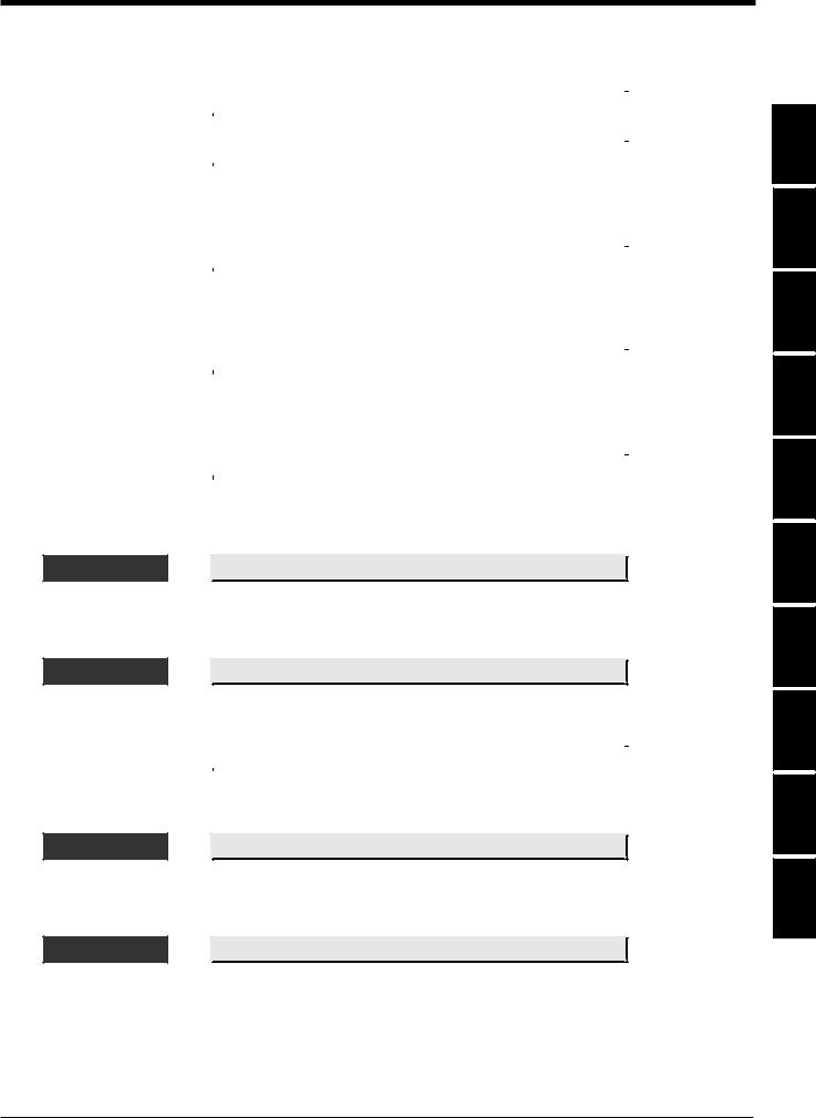
1) Warning labels
■FDA (CDRH) BL-600/601/600HA/601HA
|
|
|
|
|
AVOID EXPOSURE |
CAUTION |
|||
LASER RADIATION |
LASER RADIATION- |
|
||
IS EMITTED FROM |
DO NOT STARE INTO BEAM. |
|||
THIS APERTURE. |
|
|
||
|
|
|
|
|
|
CAUTION |
|
|
|
LASER RADIATION |
SEMICONDUCTOR LASER |
650 nm |
||
WHEN OPEN. |
MAXIMUM OUTPUT |
1.5 mW |
||
DO NOT STARE |
PULSE DURATION |
56 s |
||
INTO BEAM. |
CLASS II LASER PRODUCT |
|
||
|
|
|
|
|
BL-650HA/651HA
|
|
CAUTION |
|
AVOID EXPOSURE |
LASER RADIATION- |
|
|
LASER RADIATION |
DO NOT STARE INTO BEAM. |
||
SEMICONDUCTOR LASER |
650 nm |
||
IS EMITTED FROM |
MAXIMUM OUTPUT |
1.5 mW |
|
THIS APERTURE. |
PULSE DURATION |
56 s |
|
|
CLASS II LASER PRODUCT |
||
■ IEC/EN 60825-1 |
|
BL-600/601/600HA/601HA |
BL-650HA/651HA |
■ DIN EN |
|
BL-600/601/600HA/601HA |
BL-650HA/651HA |
2
Chapter 1 Laser Safety Precautions
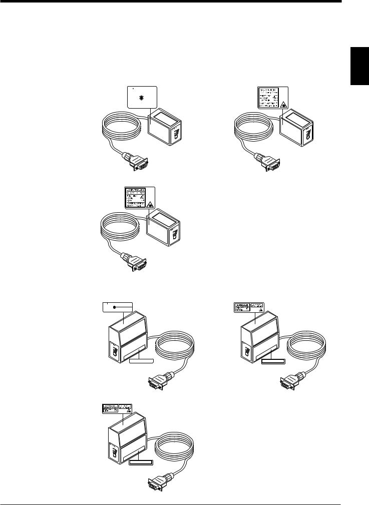
1.3Labels Location
FDA Warning labels are attached to the sensor head as shown below.
The IEC/DIN Warning labels are packaged with the BL-600 series. Affix the Warning labels on the sensor head as shown below.
■ BL-600/601/600HA/601HA |
1 |
|||||||||
FDA (CDRH) |
|
|
IEC/EN |
|||||||
|
|
|
|
|
|
|
|
|
|
|
|
|
|
|
|
|
|
|
|
|
|
|
AVOID EXPOSURE |
CAUTION |
|
|
|
|
|
|||
|
LASER RADIATION |
LASER RADIATION- |
|
|
|
|
|
|
||
|
IS EMITTED FROM |
DO NOT STARE INTO BEAM. |
|
|
|
|
||||
|
THIS APERTURE. |
|
|
|
|
|
|
|
||
|
|
|
|
|
|
|
|
|
|
|
|
|
CAUTION |
|
|
|
|
|
|
|
|
|
LASER RADIATION |
SEMICONDUCTOR LASER |
650 nm |
|
|
|
|
|||
|
WHEN OPEN. |
MAXIMUM OUTPUT |
1.5 mW |
|
|
|
|
|||
|
DO NOT STARE |
PULSE DURATION |
56 s |
|
|
|
|
|||
|
INTO BEAM. |
CLASS II LASER PRODUCT |
|
|
|
|
|
|
||
|
|
|
|
|
|
|
|
|
|
|
ON LASER
G OK/N ING TIM
TEST |
|
BL- |
600 |
|
ON LASER
OK/NGG IN TIM
TEST |
|
BL- |
600 |
DIN EN
|
ON |
LASER |
|
OK/N |
G |
|
|
TIMING |
|
TEST |
|
BL- |
600 |
|
■ BL-650HA/651HA
FDA (CDRH)
|
|
CAUTION |
|
AVOID EXPOSURE |
|
LASER RADIATION- |
|
DO NOT STARE INTO BEAM. |
|||
LASER RADIATION |
SEMICONDUCTOR LASER |
650 nm |
|
IS EMITTED FROM |
MAXIMUM OUTPUT |
1.5 mW |
|
THIS APERTURE. |
PULSE DURATION |
56 s |
|
|
CLASS II LASER PRODUCT |
|
|
LASER ON |
|
OK |
/NG |
TIM |
|
|
ING |
TEST
BL-600
CAUTION-LASER RADIATION WHEN OPEN.
DO NOT STARE INTO BEAM.
IEC/EN
LASER ON
TOK/NG
IMING
TEST
BL-600
DIN EN
LASER ON
TOK/NG
IMING
TEST
BL-600
VORSICHT-Laserstrahlung wenn Abdeckung geöffnet. Nicht in den Strahl blicken.
3

Chapter 1 Laser Safety Precautions
1.4Safety Consideration
|
|
|
|
Use of controls or adjustments or the performance of procedures other than those |
|
|
CAUTION |
|
|
|
|
|
specified herein may result in hazardous radiation exposure. |
|
1 |
|
|
|
|
|
|
|
|
|
|
|
|
The laser beam is not harmful to the skin. There is, therefore, no danger in expos- |
|
|
|
|
ing arms or hands to the beam. The only possible health hazard is in exposing the |
|
|
|
|
|
eyes to the laser beam. Damage to the eyes can occur if the operator stares |
|
|
|
|
directly into the beam. |
|
|
|
||
|
|
|
|
Follow the safety precautions below to ensure operator safety: |
|
|
WARNING |
|
|
|
|
|
• Operate the BL-600 Series only according to the procedures described in |
|
|
|
|
|
this instruction manual. |
|
|
|
|
Otherwise, injury may occur due to exposure to the laser beam. |
•Do not disassemble the sensor head.
Laser emission from the BL-600 series is not automatically stopped if the sensor head is disassembled. If you disassemble the sensor head for inspection or repair, you may be exposed to the laser beam. If the BL-600 series malfunctions, contact KEYENCE immediately.
•Do not look directly at the laser beam.
Looking directly at the laser beam may result in serious eye injury.
•Protective enclosure
We recommend that you install a protective enclosure around the sensor head to prevent any person from getting near the sensor head during operation.
•Protective goggles
We recommend that you wear protective goggles when using the BL-600 series.
•Stop laser emissions before cleaning the laser emission port.
Failure to stop the laser emission may expose eyes to the laser beam.
•Check the laser beam path.
To prevent exposure to the laser beam due to specular or diffuse reflection, install a screen which offers the appropriate reflectance and temperature characteristics to interrupt the reflected laser beam. Do not install the BL-600 series in such a way that the laser beam passes at eye height.
1.5Safety Features Provided with the BL-600 Series
The BL-600 series is provided with the following safety features. Make sure these features function correctly before operating.
•Laser emission caution LED (LASER ON LED)
During laser emission, the LASER ON LED illuminates. The LED ON status can be checked through the laser protective glasses.
•Laser forced OFF command
Sending the laser forced OFF command (LOCK, see page 116) to the BL-600 can inhibit emission of laser beams. When working near the laser transmitter, be sure to use the laser forced OFF command to avoid looking into the laser beams.
When this command is selected, the bottom STABILITY LED flashes.
4

Chapter 2
Overview
This chapter describes the package contents, basic system configuration, and operation flow.
2.1 |
Package Contents List and the BL Series Lineup .............. |
6 |
2.2 |
Part Names and Functions ................................................... |
8 |
2.3 |
System Configuration and Connection/ |
|
|
Operation Procedures ......................................................... |
12 |
2.3.1 |
Basic system configuration and connection/operation proce- |
|
|
dures for RS-232C communication........................................ |
12 |
2.3.2 |
Basic system configuration and connection/operation proce- |
|
|
dures for RS-422A communication ........................................ |
13 |
2.3.3 |
Multi-drop link communication (RS-485)................................ |
14 |
Chapter 2 Overview
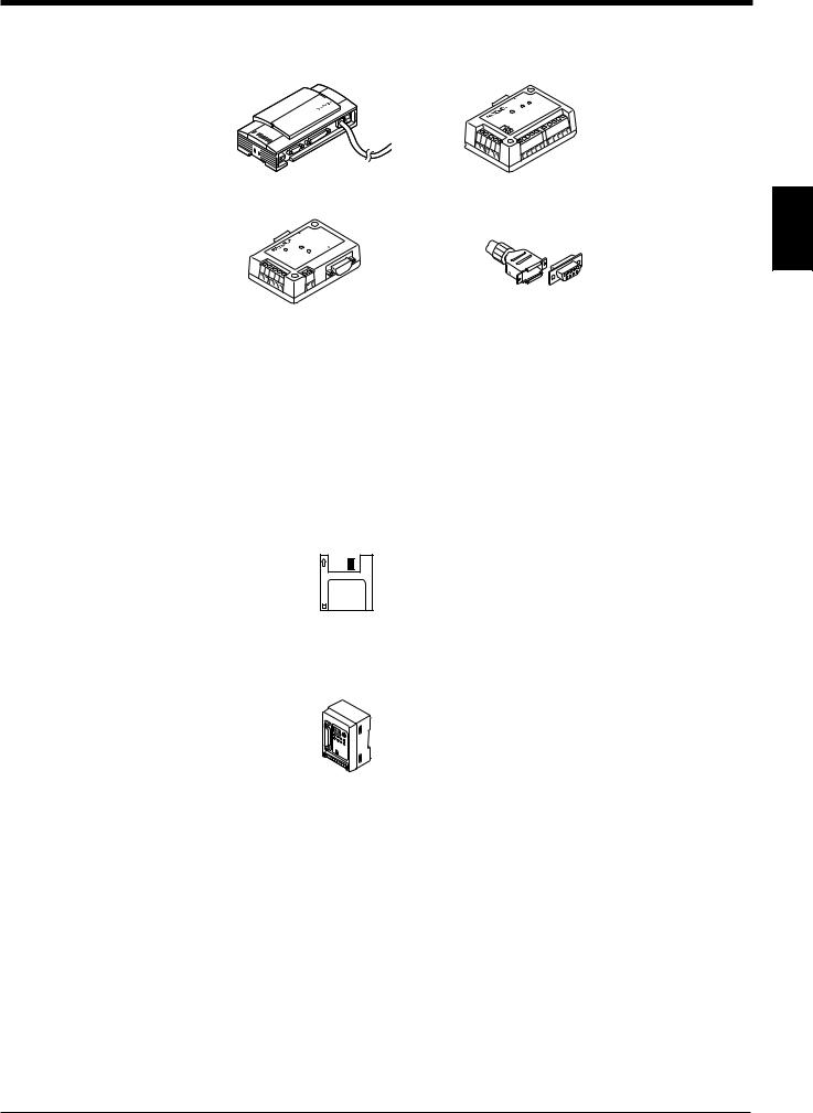
2.1Package Contents List and the BL Series Lineup
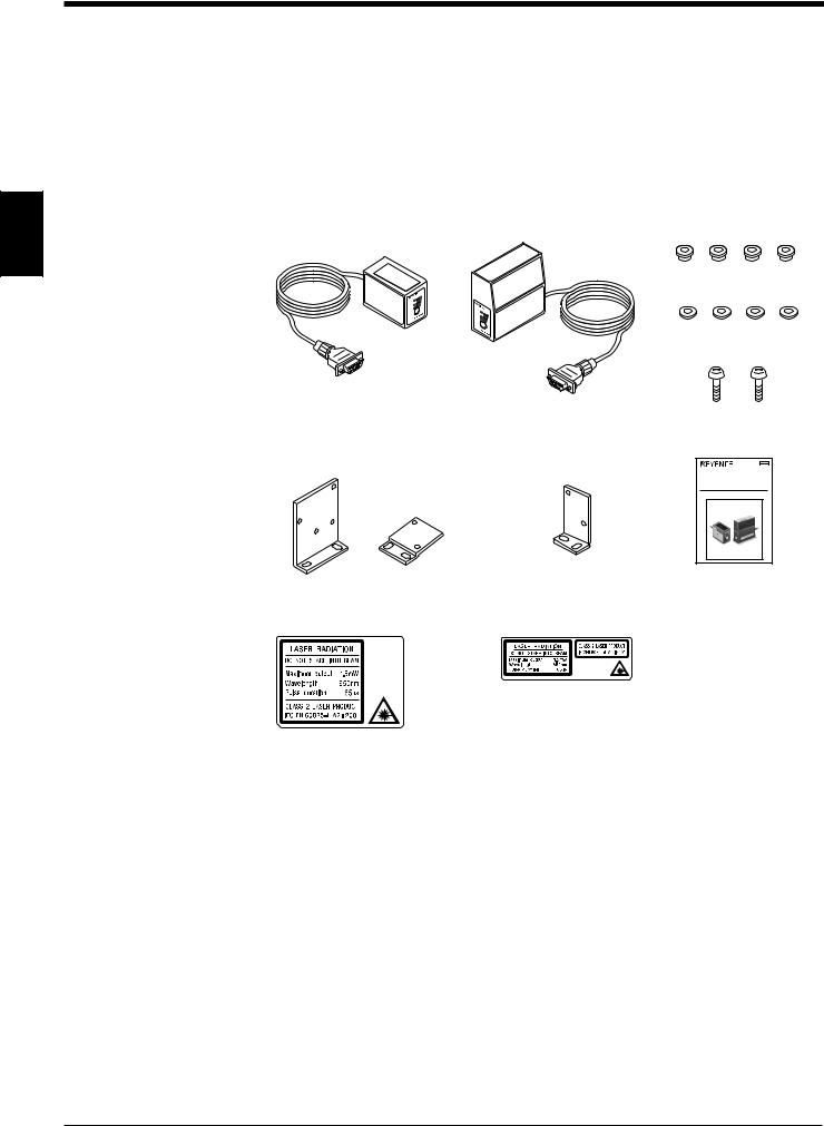
The packages of the BL-600 Series, optional power supply unit, and setup software contain the following components. Be sure to check that you have all the package contents before use.
Laser bar code reader
2
BL-600 Series (BL-600/601/600HA/601HA/650HA/651HA)
Laser bar code reader: 1 BL-600/601/600HA/601HA
ST
TE
|
BL-650HA/651HA |
Insulating spacer: 4 |
|
|
Washer: 4 |
LAS |
|
|
ER ON |
|
|
OK |
/NG |
|
T |
|
|
IMING |
|
|
|
TEST |
|
Mounting screw (M3): 2
BL-600/601/600HA/601HA BL-650HA/651HA Mounting bracket Mounting bracket : 1 A and B: 1 each
Instruction manual: 1
058-069 |
Laser Bar Code Reader |
BL-600 Series |
Instruction Manual |
Laser warning label (Japanese/English/German/French): 1
BL-600/601/600HA/601HA BL-650HA/651HA
Model |
Reading |
Scanning |
Readable bar |
Reading distance |
|
direction |
method |
width |
|||
|
|
||||
|
|
|
|
|
|
BL-600 |
|
Single |
0.19 to 1.0 mm |
75 to 330 mm |
|
BL-601 |
Front |
Raster |
(When narrow width is 1.0 mm) |
||
|
|||||
|
|
|
|
||
BL-600HA |
Single |
|
35 to 190 mm |
||
|
|
||||
BL-601HA |
|
Raster |
0.125 to 1.0 mm |
(When narrow width is 0.5 mm) |
|
|
|
|
|
||
BL-650HA |
Side |
Single |
45 to 175 mm |
||
|
|||||
BL-651HA |
Raster |
|
(When narrow width is 0.5 mm) |
||
|
|
||||
|
|
|
|
|
6
Chapter 2 Overview
Power supply (Option)
■ BL-U1 |
■ N-42/N-48 |
|
READER |
|
RD |
|
SD |
|
ER |
|
POW |
■ BL-U2 |
|
D-sub 9-pin connector, |
2 |
|
|
connector case: 1 each |
|
R |
|
|
|
EADER |
|
|
|
POWER |
SD |
-232C |
|
|
|
RD RS |
|
Model |
Supply voltage |
Interface |
|
|
|
|
|
BL-U1 |
100 to 240 V AC |
RS-232C, RS-422A, or RS-485 (multi-drop link) |
|
(Select one of these) |
|||
|
|
||
|
|
|
|
BL-U2 |
24 V DC |
RS-232C |
|
|
|
|
|
N-42 |
24 V DC |
RS-422A |
|
|
|
|
|
N-48 |
24 V DC |
RS-485(multi-drop link) |
|
|
|
|
Setup software (Option)
■ BL-H60WE
Setup software 3.5-inch floppy disk: 1
Other options
■ N-400: Multi-drop controller
Used as the master unit when multi-drop linking with the BL Series.
The package contents have been carefully inspected; however, if any component should be defective or damaged, contact your nearest KEYENCE office or distributor (listed at the end of this manual).
■ OP-27937: RS-232C Null modem cable (D-sub 9-pin)
Used for connecting BL-600 reader to optional power supply units BL-U2.
■ OP-22149: RS-232C Null modem cable
Used for connecting BL-600 reader to optional power supply units BL-U1.
■ OP-25057: 25-to 9-pin adaptor
7
Chapter 2 Overview
2.2Part Names and Functions
This section describes the part names and functions of the BL-600 Series and special power supply unit.
■ BL-600/601/600HA/601HA
8
6
2
|
ON |
|
LASER |
|
|
|
G |
|
O |
K/N |
|
ING |
|
|
TIM |
TEST |
|
|
BL- |
600 |
■ BL-650HA/651HA
6
8
LASER ON |
|
OK |
/NG |
TIM |
|
|
ING |
TEST
BL-6 00
7
7
1
2
3
LASER ON
OK/NG
TIMING
TEST
BL-600
4
5
No. |
Name |
Function |
|
|
|
|
|
1 |
LASER ON LED |
Lit when laser beams are emitted. |
|
|
|
|
|
2 |
OK/NG LED |
• When OK output is ON: The green LED lights. |
|
• When NG output is ON: The red LED lights. |
|||
|
|
||
|
|
|
|
3 |
TIMING LED |
Lit when trigger input is ON. |
|
|
|
|
|
4 |
STABILITY LED |
Displays the reading stability ( See pages 95, 98, 100.) |
|
and the BL-600 operating status. ( See the table on the |
|||
|
|
next page.) |
|
|
|
|
|
|
|
This switch allows the following operations: |
|
|
|
• Start the test mode. |
|
|
|
• Pressing the switch once within two minutes reads |
|
5 |
TEST SWITCH |
the bar code once. |
|
|
|
• Sets the communication protocol to the intival values |
|
|
|
when sending the settings. ( See page 54.) |
|
|
|
• Reset the error status. |
|
|
|
|
|
6 |
Transmitter/receiver |
Window to emit laser beams and receive reflected |
|
lights. |
|||
|
|
||
|
|
|
|
7 |
Power supply connector |
Connected to the special power supply unit. |
|
|
|
|
|
8 |
Cable |
Cable length is 1.9 m. |
|
|
|
|
8

|
|
|
Chapter 2 Overview |
||
|
|
|
|
|
|
|
STABILITY LED display according to the operating status |
||||
|
|
|
|
|
|
|
Operating status |
STABILITY LED display |
Action to be taken |
|
|
|
|
|
|
|
|
|
Power-on |
LEDs turn on sequentially |
–––––– |
|
|
|
starting from the bottom. |
|
|||
|
|
|
|
|
|
|
|
|
|
|
|
|
During setup |
All the LEDs flash. |
–––––– |
|
|
|
See pages 116, 118. |
|
|||
|
|
|
|
|
|
|
Waiting for setting data |
The first, third, and fifth |
|
|
|
|
send/receive |
LEDs from the top flash |
–––––– |
|
|
|
See page 54. |
simultaneously. |
|
|
|
|
Laser forced OFF |
The bottom LED flashes. |
–––––– |
|
|
|
When LOCK command is |
|
2 |
||
|
sent, see page 116. |
|
|
|
|
|
|
|
|
|
|
|
|
|
|
|
|
|
|
|
The BL-600 Series may have |
|
|
|
|
Either of the second, third, |
failed or the supply voltage may |
|
|
|
Unit error |
have dropped. If the voltage is |
|
|
|
|
or forth LEDs from the top |
|
|
||
|
|
flashes. |
normal, the unit may have a |
|
|
|
|
problem. Contact your nearest |
|
|
|
|
|
|
|
||
|
|
|
KEYENCE office or distributor. |
|
|
|
|
|
|
|
|
|
PLC link error |
The top LED flashes. |
Press the TEST switch to reset |
|
|
|
See page 142. |
the error. |
|
|
|
|
|
|
|||
|
|
|
|
|
|
9

Chapter 2 Overview
■ BL-U1
6
|
|
9 |
2 |
1 |
|
3 |
|
|
|
2 |
10 |
|
|
|
|
4 |
|
|
8 |
7 |
11
5
12
No. |
Name |
Function |
|
|
|
|
|
1 |
POWER LED |
Lit when power is ON. |
|
|
|
|
|
|
|
• Allows you to monitor the communication status of |
|
2 |
Communication status |
the RS-232C port. |
|
indicator LEDs |
• The SD, RD, RS and CS indicators are provided in |
||
|
|||
|
|
this order from the top. |
|
|
|
|
|
3 |
TIMING LED |
Lit when trigger input is ON. |
|
|
|
|
|
4 |
OK/NG LED |
• When OK output is ON: The green LED lights. |
|
• When NG output is ON: The red LED lights. |
|||
|
|
||
|
|
|
|
|
|
Includes the trigger input terminal, OK/NG output |
|
5 |
I/O terminal block |
terminals, and RS-422A/RS-485 (multi-drop link) |
|
|
|
connecting terminals. |
|
|
|
|
|
6 |
RS-232C port |
Used to connect to a personal computer. This port is |
|
unused when RS-485 (multi-drop link) is used. |
|||
|
|
||
|
|
|
|
7 |
READER port |
Connect the BL-600 Series to this port. |
|
|
|
|
|
8 |
DIP switches |
Switches the communication port, and turns the |
|
terminator ON/OFF. |
|||
|
|
||
|
|
|
|
9 |
Power switch |
Tuns the power ON/OFF. |
|
|
|
|
|
10 |
Power supply cable |
Use a 100 to 240 V AC (50/60 Hz) power supply. |
|
Cable lenght is 2 m. |
|||
|
|
||
|
|
|
|
11 |
Mounting bracket |
Used when the BL-U1 is mounted with screws. |
|
|
|
|
|
12 |
DIN-rail mounting claw |
Used when the BL-U1 is mounted to a DIN rail. |
|
|
|
|
10
Chapter 2 Overview
■ BL-U2
8
1
2
3
READER |
|
|
|
POWER |
SD |
|
-232C |
|
|
RD |
RS |
8
7
6
5
4 |
2 |
|
No. |
Name |
Function |
|
|
|
|
|
1 |
READER port |
Connect to a BL-600 Series bar code reader. |
|
|
|
|
|
2 |
TRIGGER input terminals |
Connect to a photoelectric sensor for trigger input. |
|
|
|
|
|
3 |
OK/NG output terminals |
Output OK/NG signals. |
|
|
|
|
|
4 |
Power supply terminals |
Connect to a 24 V DC power supply. |
|
|
|
|
|
5 |
RS-232C port |
Connect to a personal computer, etc. |
|
|
|
|
|
|
Communication status |
• Indicate the communication status of the RS-232C. |
|
6 |
• The SD and RD indicators are provided in this order |
||
indicator LEDs |
|||
|
from the top. |
||
|
|
||
|
|
|
|
7 |
POWER LED |
Light when the power is on. |
|
|
|
|
|
8 |
Mounting hole |
Used when the BL-U2 is mounted with screws. |
|
|
|
|
■ N-42
8 9
1
2
3
4
 READER RD SD
POWER
TERMINATORON
OFF
7
6
5
9
|
No. |
Name |
Function |
|
|
|
|
|
1 |
READER port |
Connect to a BL-600 Series bar code reader. |
|
|
|
|
|
2 |
Terminator switch |
Turns ON/OFF the terminator |
|
(Termination resistance: 100 Ω). |
||
|
|
|
|
|
|
|
|
|
3 |
TRIGGER input terminals |
Connect to a photoelectric sensor for trigger input. |
|
|
|
|
|
4 |
OK/NG output terminals |
Output OK/NG signals. |
|
|
|
|
|
5 |
Power supply terminals |
Connect to a 24 V DC power supply. |
|
|
|
|
|
6 |
RS-422A terminals |
Connect to an RS-422A device. |
|
|
|
|
|
|
Communication status |
• Indicates the communication status of the RS-422A. |
|
7 |
• The SD and RD indicators are provided in this order |
|
|
indicator LEDs |
||
|
|
from the left. |
|
|
|
|
|
|
|
|
|
|
8 |
POWER LED |
Light when the power is turned ON. |
|
|
|
|
|
9 |
Mounting hole |
Used when the N-42 is mounted with screws. |
|
|
|
|
|
|
|
|
11
Chapter 2 Overview
2.3System Configuration and Connection/Operation Procedures
This section describes the basic system configuration and the connection/operation procedures to use RS-232C, RS-422A, or multi-drop link.
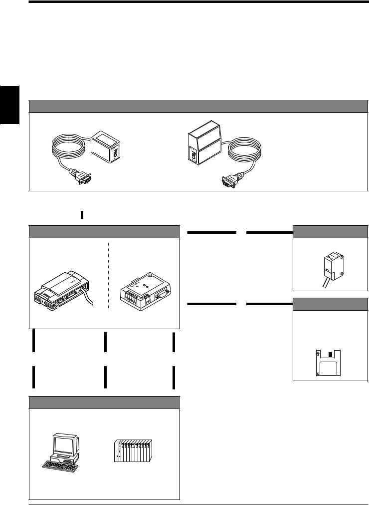
2.3.1Basic system configuration and connection/operation procedures for RS-232C communication
2 |
BL-600 Series |
|
BL-600/601/600HA/601HA |
BL-650HA/651HA |
6 Installation |
|
|
|
|
|
See pages 72 to 80. |
LA |
SER ON |
|
|
OK |
|
T |
/NG |
|
IMING |
TEST
TEST
•Check before installation
•Position adjustment using test mode
•Installation
|
|
|
Connection to the READER port |
|
1 |
||||
With the BL-U1 See page 16. |
||||
▼With the BL-U2 See page 25.
Optional power supply unit |
▼ |
7 |
|||
Connection |
|||||
2 DIP switch setting |
|
|
|
||
|
|
With the BL-U1 See page 19. |
|||
See page 17. |
|
|
With the BL-U2 See page 27. |
||
BL-U1 |
BL-U2 |
|
|
|
|
|
ER |
|
|
|
|
|
READ |
|
|
|
|
|
POWER SD |
-232C |
|
|
|
|
|
RD RS |
|
|
|
4 Power-up |
▼ |
5 |
||
|
||||
Setting of the BL-600 Series |
||||
(Use one of these setup tools.) |
||||
|
|
|||
|
▲ |
▲ |
|
|
Connection |
Serial communi- |
PLC link |
|
|
With the BL-U1 |
cation |
See “Chapter 8, PLC Link.” |
||
3 See pages 20 to 23. |
8 See “Chapter 7, |
9 |
|
|
With the BL-U2 |
Serial Communication.” |
|
||
See pages 28 to 30. |
|
|
|
|
▼ |
▼ |
▼ |
|
|
Host computer |
|
|
||
Trigger input
Photoelectric sensor
Setup tools
Setup software BL-H60WE
See “Chapter 4, Setup
Software.”
PC |
PLC (RS-232C link unit) |
|||||||||||||
|
|
|
|
|
|
|
|
|
|
|
|
|
|
|
|
|
|
|
|
|
|
|
|
|
|
|
|
|
|
|
|
|
|
|
|
|
|
|
|
|
|
|
|
|
12
Chapter 2 Overview
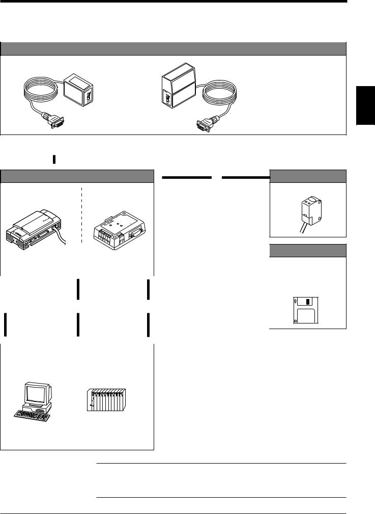
2.3.2Basic system configuration and connection/operation procedures for RS-422A communication
BL-600 Series
BL-600/601/600HA/601HA BL-650HA/651HA
LASER O
N
O
TIK/NG
MING
ST
TE
TEST
6 Installation
See pages 72 to 80.
•Check before installation
•Position adjustment using
test mode |
2 |
|
•Installation
|
|
|
Connection to the READER port |
|
1 |
||||
With the BL-U1 See page 16. |
||||
▼With the BL-N42 See page 25.
Optional power supply unit |
▼ |
7 |
|
|
|||
2 DIP switch setting |
|
Connection |
|
|
With the BL-U1 See page 19. |
||
See page 17. |
|
With the BL-N42 See page 27. |
|
READER |
|
|
|
ER SD |
-232C |
|
|
POW |
S |
|
|
|
RD R |
|
|
|
|
|
|
|
|
|
|
|
|
▼ |
5 |
|
||
|
|
|
|
|
|
|
|
|
|
|
|
|
|
|
|
|
|
|
|
|
|
|
|
|
|
|
|
|
|
|
|
|
|
|
|
|
|
|
|
|
|
|
|
|
|
|
|
|
4 Power-up |
|
|
|
|
|
|
||||
|
|
|
|
|
|
|
Setting of the BL-600 Series |
|||||||
|
|
|
|
|
|
|
||||||||
|
|
|
|
|
|
|
(Use one of these setup tools.) |
|||||||
|
|
|
|
|
|
|
|
|
|
|
|
|||
|
|
|
|
|
|
|
|
|
|
|
|
|
|
|
|
|
|
|
Connection |
▲ |
▲ |
|
|
|
|
||||
|
|
|
|
With the BL-U1 |
|
|
|
Serial communi- |
|
|
PLC link |
|
|
|
|
|
|
|
See pages 23 to 24. |
|
|
|
cation |
|
|
See “Chapter 8, PLC Link.” |
|||
|
3 |
|
8 |
9 |
|
|||||||||
|
With the BL-N42 |
|
See “Chapter 7, |
|
|
|
|
|
||||||
|
|
|
|
See pages 31 to 32. |
|
|
|
Serial Communication.” |
|
|
|
|
|
|
|
|
|
|
|
|
|
|
|
|
|||||
▼ |
▼ |
▼ |
|
|
||||||||||
|
|
|||||||||||||
|
|
|
|
Host computer |
|
|
|
|
|
|
||||
Trigger input
Photoelectric sensor
Setup tools
Setup software BL-H60WE
See “Chapter 4, Setup
Software.”
PC |
PLC (RS-422A link unit) |
|||||||||||||
|
|
|
|
|
|
|
|
|
|
|
|
|
|
|
|
|
|
|
|
|
|
|
|
|
|
|
|
|
|
|
|
|
|
|
|
|
|
|
|
|
|
|
|
|
Note: When the N-42 is used as a power supply unit, the communication type is set to RS-422A, therefore the BL-600 Series cannot be connected directly to a personal computer. To set the BL-600 Series with a personal computer, use an RS-232C type power supply unit (BL-U1 or BL-U2).
13
Chapter 2 Overview
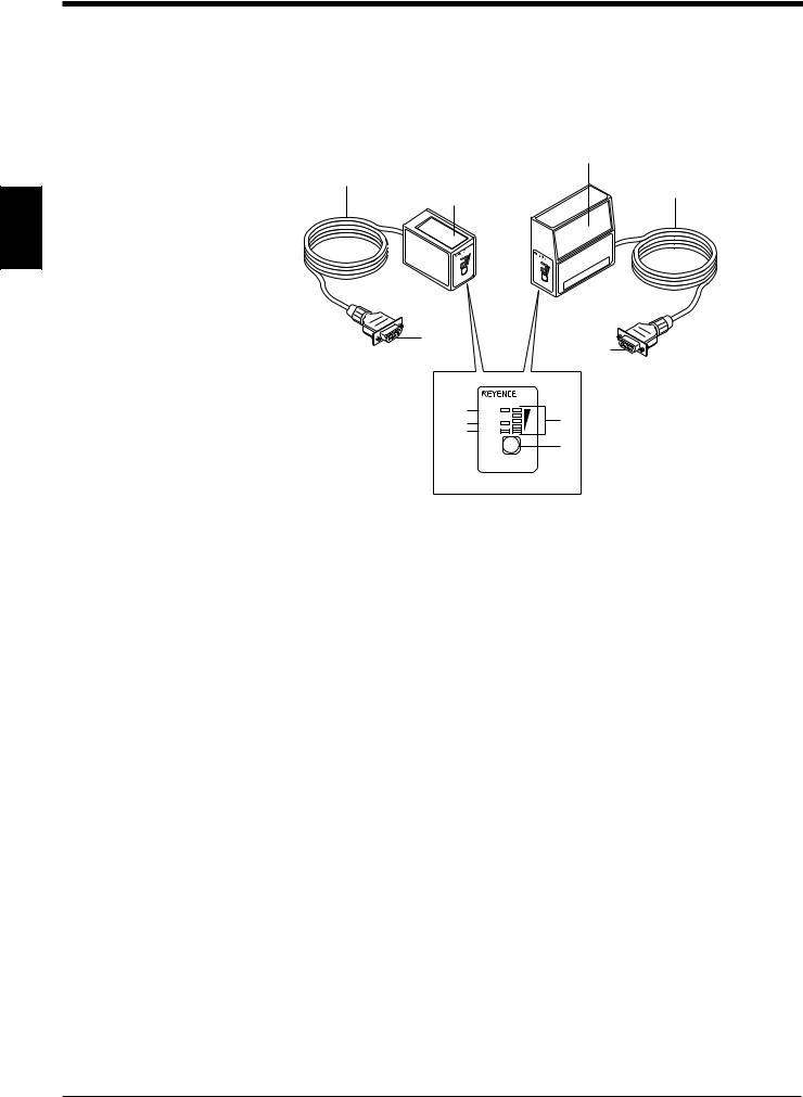
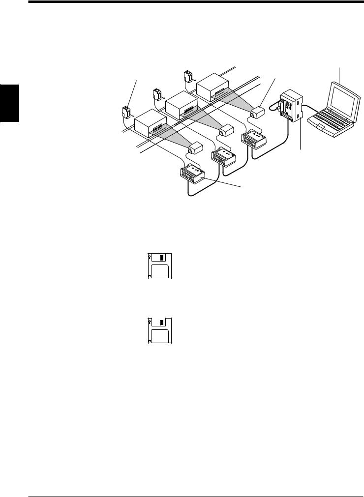
2.3.3 Multi-drop link communication (RS-485)
The following devices are required for the multi-drop link to control several BL-600
Series units with a host computer.
Host computer (PC)
Photoelectric sensor |
BL-600 Series |
(PZ2 Series, etc.) |
2
Multi-drop controller (N-400)
Optional power supply unit (BL-U1, N-48)
■ BL-600 Series setup tools
Setup software BL-H60WE
■ N-400 setup tools
Setup software (Provided with N-400)
Refer to the N-400 User’s Manual for connection and usage of the multi-drop link.
14

Chapter 3
Connection and Installation
This chapter describes the connections and wiring between the BL-600 Series, special power supply unit, and peripheral devices.
3.1 |
Connecting BL-U1 and Wiring ........................................... |
16 |
3.1.1 |
Connecting the BL-U1, AC power supply, |
|
|
and BL-600 Series ................................................................. |
16 |
3.1.2 |
DIP switch setting .................................................................. |
17 |
3.1.3 |
Terminals of I/O terminal block and wiring ............................. |
18 |
3.1.4 |
Connecting RS-232C ............................................................. |
20 |
3.1.5 |
Wiring the RS-422A ............................................................... |
23 |
3.2 |
Connecting the BL-U2/N-42 and Wiring ............................ |
25 |
3.2.1 |
Connecting the BL-U2/N-42, AC power supply, |
|
|
and BL-600 Series ................................................................. |
25 |
3.2.2 |
Terminals of I/O terminal block and connections ................... |
26 |
3.2.3 |
Connecting RS-232C (BL-U2) ............................................... |
28 |
3.2.4 |
Connecting the N-42 to RS-422A .......................................... |
31 |
3.3 |
Wiring without the Special Power Supply Units .............. |
33 |
3.3.1 |
Pin assignments of the BL-600 Series connector |
|
|
and the connecting power supply .......................................... |
33 |
3.3.2 |
I/O Wiring ............................................................................... |
34 |
3.3.3 |
RS-232C connection .............................................................. |
35 |
Chapter 3 Connection and Installation
3.1Connecting BL-U1 and Wiring
This section describes the connection and wiring of the BL-600 Series and peripheral devices when the special power supply unit BL-U1 is used.
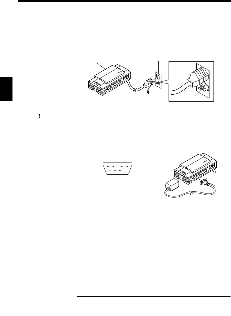
3.1.1Connecting the BL-U1, AC power supply, and BL-600 Series
1.Plug the BL-U1 power cable into an outlet.
Outlet
BL-U1
Power plug
3
FG line
|
CAUTION |
|
Do not use a power supply other than 100 to 240 V AC (50/60 Hz). |
|
|
An improper power supply may cause product failure. |
|
|
|
|
|
|
|
|
Note: If the noise conveyed through the FG line causes an LB-600 Series reading |
|
|
|
error, do not connect the FG line. |
|
|
|
2. Connect the BL-600 Series to the READER port of the BL-U1. |
|
|
|
■ BL-U1 READER port pin assignment |
1 2 3 4 5
BL-600 Series
6 7 8 9
D-sub 9-pin (male)
DCE specification (defined as terminal) #4-40 screw (female)
READER port
Connector
Pin No. |
Symbol |
Function |
Signal |
|
direction |
||||
|
|
|
||
|
|
|
|
|
1 |
TIM |
Trigger input |
Output |
|
|
|
|
|
|
2 |
RD (RXD) |
Sends RS-232C data. |
Output |
|
|
|
|
|
|
3 |
SD (TXD) |
Receives RS-232C data. |
Input |
|
|
|
|
|
|
4 |
OK |
OK |
Input |
|
|
|
|
|
|
5 |
GND (SG) |
Ground (Common ground for respective signal) |
–– |
|
|
|
|
|
|
6 |
NG |
NG |
Input |
|
|
|
|
|
|
7 |
RS (RTS) |
Ready to send RS-232C data. |
Input |
|
|
|
|
|
|
|
|
Request to send RS-232C data. |
|
|
8 |
CS (CTS) |
(Control method can be selected with the DIP |
Output |
|
|
|
switches.) See page 17. |
|
|
|
|
|
|
|
9 |
+5 V |
+5 V power supply |
Output |
|
|
|
|
|
|
|
|
|
|
Note: Do not extend the power cable. A long power cable can cause a voltage drop, preventing the BL-600 from starting properly.
16

Chapter 3 Connection and Installation
3.1.2 DIP switch setting
Change the DIP switch setting according to the type of communication and terminator setting.
■ DIP switch
Switch
OFF |
|
|
|
|
|
|
|
ON |
1 |
2 |
3 |
4 |
5 |
6 |
|
|
|
||||||
* The figure above shows the factory-settings. |
DIP switch |
||||||
|
|
|
|
|
|
|
|
|
3 |
DIP Switch No. |
|
1 |
2 |
3 |
4 |
5 |
6 |
|
|
|
|
|
|||||||
|
|
|
|
|
|
|
|
|
|
|
RS-232C |
ON |
OFF |
OFF |
|
|
|
|
|
|
(Factory-setting) |
|
|
|
|
|
|||
Communication type |
|
|
|
|
|
|
|
|
|
|
|
|
|
|
|
|
|
|
|
RS-422A |
OFF |
ON |
OFF |
|
|
|
|
|
|
selection |
|
|
|
|
|
||||
|
|
|
|
|
|
|
|
|
|
RS-485 |
OFF |
OFF |
ON |
|
|
|
|
|
|
|
|
|
|
|
|
||||
|
(Multi-drop link) |
|
|
|
|
|
|||
|
|
|
|
|
|
|
|
|
|
|
|
|
|
|
|
|
|
|
|
RS-422A terminator |
OFF |
|
|
|
OFF |
|
|
|
|
(Termination |
|
|
|
|
|
|
|
|
|
ON |
|
|
|
ON |
|
|
|
|
|
resistance: 100 Ω) |
|
|
|
|
|
|
|
||
RS-485 terminator |
OFF |
|
|
|
|
OFF |
|
|
|
(Termination |
|
|
|
|
|
|
|
|
|
ON |
|
|
|
|
ON |
|
|
|
|
resistance: 100 Ω) |
|
|
|
|
|
|
|
||
|
|
|
|
|
|
|
|
|
|
|
ON or OFF according |
|
|
|
|
|
|
|
|
Selection of READER |
to the RS-232C port |
|
|
|
|
|
OFF |
|
|
port CS control method |
CS signal status. |
|
|
|
|
|
|
|
|
|
Normally ON |
|
|
|
|
|
ON |
|
|
|
|
|
|
|
|
|
|
|
|
17
Chapter 3 Connection and Installation
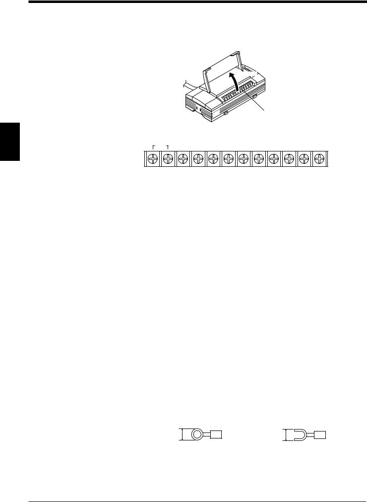
3.1.3 Terminals of I/O terminal block and wiring
Terminals of the I/O terminal block
The terminals of the I/O terminal block are assigned as shown in the figure.
Open
|
|
I/O terminal block |
3 |
■ Terminal assignment |
|
TIM |
+12V OUTCOM OK NG SDA SDB SG RDA RDB |
|
|
|
|
|
|
|
|
|
|
|
|
|
|
|
|
|
|
|
|
|
|
|
|
|
Trigger input |
|
|
OK/NG output |
RS-422A/RS-485 |
|||||||
|
|
Power supply for the |
|
|
|
|
|
||||
|
|
sensor (12 V DC, 300 mA) |
|
|
|||||||
Symbol |
Description |
Signal |
|
direction |
|||
|
|
||
|
|
|
|
TIM |
Trigger input |
Input |
|
|
|||
Input |
|||
|
|
||
|
|
|
|
+12 V OUT- |
+ terminal of power supply for sensor (12 V DC, 300 mA) |
Output |
|
|
|
||
– terminal of power supply for sensor (0 V) |
Output |
||
|
|||
|
|
|
|
COM |
Common terminal for OK/NG output |
— |
|
|
|
|
|
OK |
OK output |
Output |
|
|
|
|
|
NG |
NG output |
Output |
|
|
|
|
|
SDA |
+ terminal for RS-422A data transmission/RS-485 + terminal |
Output, |
|
Input/Output |
|||
|
|
||
|
|
|
|
SDB |
– terminal for RS-422A data transmission/RS-485 - terminal |
Output, |
|
Input/Output |
|||
|
|
||
|
|
|
|
SG |
Signal ground |
— |
|
|
|
|
|
RDA |
+ terminal for RS-422A data reception |
Input |
|
|
|
|
|
RDB |
– terminal for RS-422A data reception |
Input |
|
|
|
|
Applicable crimp terminals
M3.0 screws are used for the terminal block.
Use the following crimp terminal for connection.
■ Shape of applicable crimp terminal
Round-shape |
Fork-shape |
6.0 mm or |
6.0 mm or |
less |
less |
18
Chapter 3 Connection and Installation
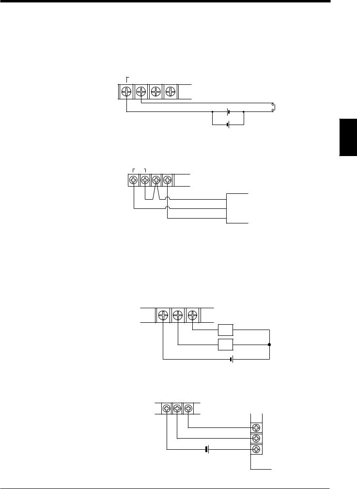
Connecting trigger input
The trigger input allows the BL-600 Series to start reading bar codes (turn on the laser beam).
The trigger input is turned ON when 8.5 to 30 V DC input is activated between the trigger input terminals.
The BL-U1’s power supply terminals for the sensor can be used as the power supply input for the sensor.
TIM |
|
+12 V OUT– |
|
||
|
|
|
+ |
Contact or |
solid-state |
|
+ |
|
8.5 to 30 V DC |
3 |
|
■ Connection to a photoelectric sensor manufactured by KEYENCE
TIM +12 V OUT–
Photoelectric sensor
 Brown (Red)
 Black (White)
 Blue (Black)
Connecting the OK/NG output
The OK/NG output is used to differentiate between acceptable and unacceptable results based on a comparison with preset data ( See pages 101.). It can also be used to indicate whether or not the BL-600 Series successfully reads bar codes when there is no preset data entered.
The OK/NG output is an NPN open-collector output.
COM OK NG
*Rated load: 30 V DC max. (100 mA)
Load
Load
+
■Connection to a programmable logic controller (PLC) manufactured by KEYENCE
COM OK NG
PLC
0001
0000
C
+
19
Chapter 3 Connection and Installation
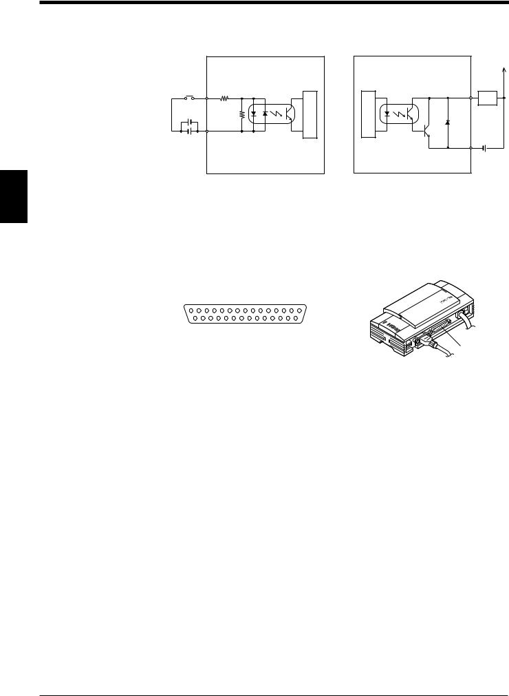
I/O circuit diagram
■ Input circuit diagram
|
3.3 kΩ |
||
+ |
TIM |
2.4 |
|
kΩ |
|||
|
|||
+
Internal circuit
■ Output circuit diagram
OK/NG |
|
circuitInternal |
Load |
|
|
COM |
+ |
3
3.1.4 Connecting RS-232C
Pin assignment of the RS-232C port
The BL-U1 has a RS-232C port with the following pin assignment.
■ RS-232C port pin assignment
13 |
1 |
25 |
14 |
D-sub 25-pin (female) |
|
|
DTE specification (defined as terminal) |
RS-232C port |
|
M2.6 screw (female) |
||
|
Pin No. |
Symbol |
Function |
Signal |
|
direction |
||||
|
|
|
||
|
|
|
|
|
1 |
FG |
Frame ground |
— |
|
|
|
|
|
|
2 |
SD (TXD) |
Sends RS-232C data |
Output |
|
|
|
|
|
|
3 |
RD (RXD) |
Receives RS-232C data |
Input |
|
|
|
|
|
|
4 |
RS (RTS) |
Request to send RS-232C data (always ON) |
Output |
|
|
|
|
|
|
5 |
CS (CTS) |
Ready to send RS-232C data |
Input |
|
|
|
|
|
|
6 |
DR (DSR) |
Connected to pin No. 20 inside. |
Input |
|
|
|
|
|
|
7 |
GND (SG) |
Signal ground |
— |
|
|
|
|
|
|
20 |
ER (DTR) |
Connected to pin No. 6 inside. |
Output |
|
|
|
|
|
20
 Loading...