


Installation
Instructions
Durametallic® MD-200 Series
Conditioned Gas Dual Cartridge
Canister Seal for Mixers and Agitators
Experience In Motion

1 Equipment Check
1.1Follow plant safety regulations prior to equipment disassembly:
•Consult the plant Material Safety Data Sheet (MSDS) files for hazardous material regulation.
•Wear designated personal safety equipment.
•Lock out the mixer or agitator motor and valves to and from the vessel.
•Relieve any pressure in the vessel.
•Use plant vessel entry procedures if it is necessary to enter the vessel.
1.2Secure the mixer or agitator shaft in accordance with the mixer or agitator manufacturer’s instructions.
1.3Remove the coupling and/or drive to access the seal area. Follow the manufacturer’s instructions.
1.4Remove the existing seal assembly.
1.5Remove all burrs and sharp edges from the shaft and vessel flange area. The shaft and vessel flange must be free of burrs, sharp edges, cuts, dents, or corrosion that might cause leakage past the sleeve packing O-rings and the vessel flange O-ring gasket.
1.6Check requirements for the shaft and the vessel flange. They must agree with the dimensions shown in Figure 1.
1.7Check the assembly drawing accompanying the seal assembly for specific seal design data, materials of construction, dimensions, and recommended piping connections.
1.8Check the shaft OD, vessel flange bolt size, bolt circle, and distance to the coupling or drive to ensure that these dimensions agree with the seal assembly drawing provided.
1.9Handle the seal assembly with care, it is manufactured to precise tolerances. The sealing faces of the rotors and the stators are of special importance. These sealing faces are lapped to rigid specifications required for contacting face gas seals. If it becomes necessary to disassemble the seal, keep these sealing faces clean and dry at all times and protect them from damage since they are subject to impact fracture.
The images of parts shown in these instructions may differ visually from the actual parts due to manufacturing processes that do not affect the part function or quality.
2
1.10Pressure testing of this cartridge canister dual seal prior to installation is possible using filtered dry nitrogen or instrument air. Consult Flowserve, Flow Solutions for acceptable gas leakage rates for this seal design.
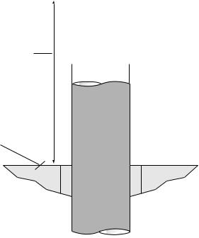
Mixer/Agitator Shaft and Flange Requirements |
Figure 1 |
To first obstruction
(See assembly drawing)
Face of vessel flange to be square to the axis of the shaft to within 0.25 mm (0.010 inch) FIM and have a √1.6 µm (63 µinch) Ra finish or better


 Shaft OD to be +0.025 mm (+0.001 inch)
-0.025 mm (-0.001 inch)
with a surface finish of √ 0.8 µm
(32 µinch) Ra or better
•Bearings, drive, and coupling must be in good condition
•Maximum vertical shaft movement (axial end play) = 0.61 mm (0.024 inch) FIM
•Maximum static vessel flange out of concentricity = 0.50 mm (0.020 inch) FIM
•Maximum static vessel flange to shaft out of squareness = 0.25 mm (0.010 inch) FIM
•Maximum dynamic shaft deflection = 3 mm (0.125 inch) FIM
The MD-200 Seal design may include an optional radial bearing in the canister to protect the seal from excessive shaft runout or whip.
3
 Loading...